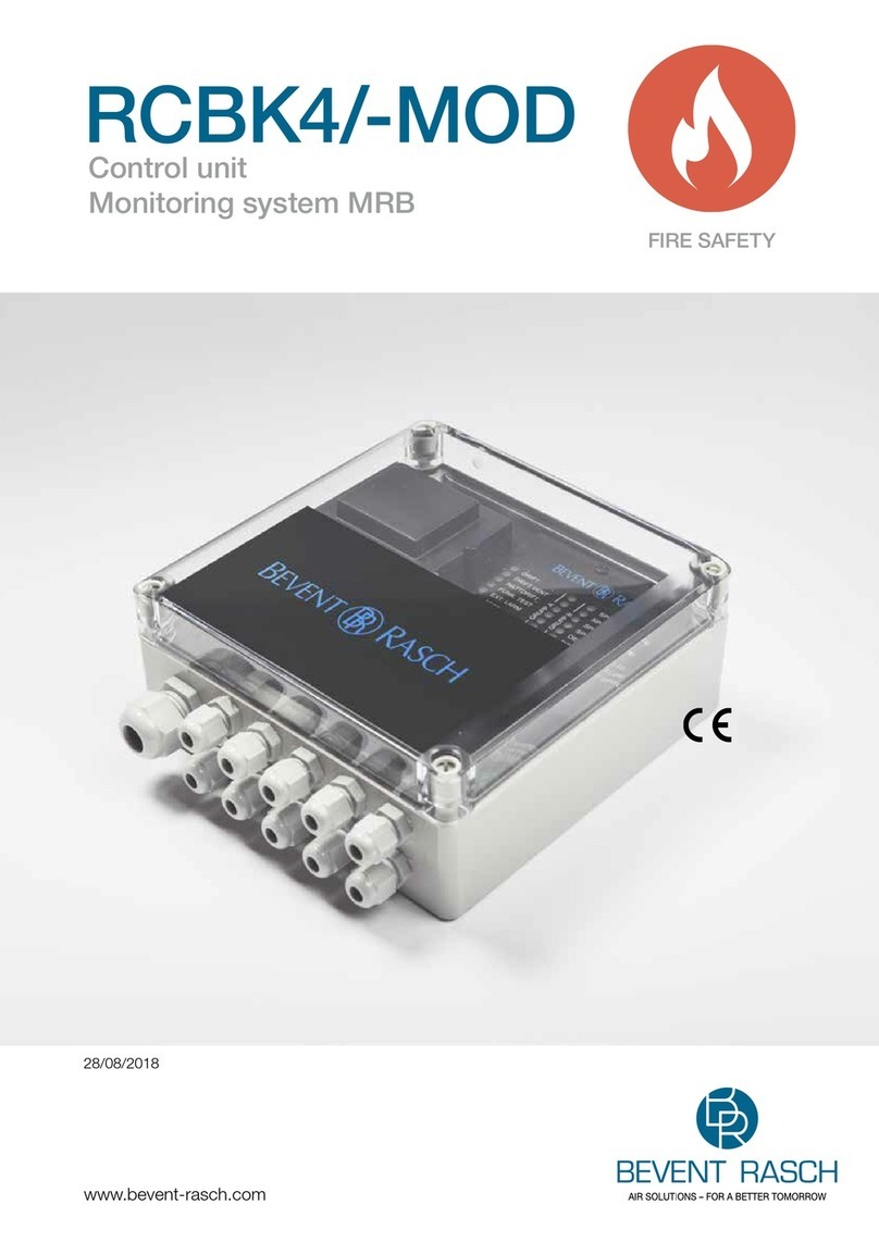
EnergAir metacentre DX Box User manual

MANY0739A.GB – Metacentre DX Box User Manual
TM
DX Box
bar

Metacentre DX Box
Page 1
Index
1.0 Introduction
1.1 Management System Connectivity
1.2 Basic Function
1.3 Operation
2.0 Operation
2.1 User Interface
2.2 Display
2.3 Status Symbols
2.4 Indications
2.5 Compressor Identification
2.6 Operation
2.7 Power Failure Auto-Restart
2.8 Failure Modes
2.9 Compressor Fault
2.10 DX Box Fault
2.11 Pressure Sensor Fault
3.0 Parts List
4.0 Technical Data
5.0 Wiring Connection Diagram
Refere to Section Indicated
Note
Important or Caution, Safety
Health and Safety
Refer to Metacentre Safety Manual

User Manual
Page 2
1. INTRODUCTION
The DX Box is designed to connect two
load/unload air compressors to a system
management unit, using a 2-wire RS485 data
cable up to 500m (1650ft) in length.
The DX Box is designed specifically to ‘group’
two compressors together as a single
coherent unit. The system management unit
will detect and manipulate the two
compressors as a single multiple step or
variable output compressor unit.
The DX Box is able to manipulate two identical
capacity compressors to form a single ‘group’
that will act in an identical manner as a 3-step
compressor. The DX Box is also able to
manipulate two differential capacity
compressors providing demand matched
control and sequence to form a single ‘group’
that will act in an identical manner as a
variable stepping output, compressor.
This functionality provides the ability to:
a) Group two adjacent air compressors
together as a single coherent unit.
b) Combine two similar capacity
compressors together to form a three-
step variable output group acting as a
single coherent variable output unit.
c) Take advantage of a small or minimal
capacity compressor, grouped
together with a medium or higher
capacity compressor, to form a high
capacity, variable output, group acting
as a single variable output ‘top-up’
compressor.
d) Exceed the maximum compressor
control capability of a system
management unit by combining
compressors together as one.
Two single pressure switch control type air
compressors can be connected to the DX Box
using a 6-wire cable and a compressor
interface PCB (i-PCB). The ‘i-PCB’
connections are identical to an system
management unit.
The DX Box also provides optional ‘local
pressure sensor’ connections. The
compressor delivery pressures, local system
pressure and air treatment differential
pressures can be displayed. The monitored
local pressure is available on the system
network and can be utilised by an system
management unit for advanced pressure
related functions.
Any number of DX Boxes can be connected to
an system management unit as long as the
total number of single compressors and/or
groups does not exceed the total number of
compressors for the system management unit
model.
1.1 Management System Connectivity
12 #1
DX Box
3#2
The DX Box connects to an ystem
management unit using an industrial two wire
RS485 data network (Multi485).
1.2 Basic Function
The DX Box is a ‘Duel unit eXtension’ to a
system management unit providing the ability
to group two individual air compressors
together in to one duel ‘group’ acting as a
single coherent unit.
The DX Box provides additional ‘i-PCB’
connectivity.
The DX Box can also be used to provide ‘i-
PCB’ connectivity at a remote location beyond
the maximum distance specification of direct
system management unit connection.
1.3 Operation
2.3.1 Timer Rotation Mode (Tr)
#1 #2
50% 50% = 100%
1AB
2BA
AB
Timer Rotation should be used when the two
compressors have the same (50:50), or very
similar, output capacity. The DX Box will
assign one compressor as ‘Duty’ and the other
as ‘Standby’. The duty compressor will always
be loaded first and the standby used as and
when required to meet demand. The duty and
standby assignment will be changed at every
‘Interval Time’ (adjustable).

Metacentre DX Box
Page 3
1.3.2 Automatic Mode (Ar)
#1 #2
65% 35% = 100%
0% - -
35% - B
65% A -
100% A B
AB
Automatic mode can be used when the
compressor capacities are different. The DX
Box will utilise each compressor as required to
match output to demand. This mode enables
the compressor ‘group’ to behave in the same
manner as a single (multiple step) variable
output unit.
The set ‘Interval Time’ is ignored in this mode,
the DX Box will continuously evaluated
utilisation to match demand.
For example:
If demand can be satisfied by the smaller of
the two compressors (demand < 36%) the DX
Box will utilise the lower capacity compressor
(B). If demand increases above the output
capacity of the smaller compressor, but within
the capacity of the larger capacity compressor,
the DX Box will utilise the larger capacity
compressor (A). If demand exceeds to
capacity of the larger capacity compressor the
DX Box will load the larger compressor
continuously and utilise the smaller capacity
compressor to regulate as required.
1.3.3 Management System Integration
When integrated with a system management
unit the DX Box compressor ‘group’ will
respond in ‘Top-Up’ mode or ‘Base-Load’
mode as dictated by the management unit.
The assigned mode of response will change
from time-to-time dependant on the set
sequencing mode of the management unit.
In Top-Up’ mode the DX Box will allow
variable capacity control (as described above)
dependant on demand.
In ‘Base-Load’ mode the DX Box will fully load
both compressors to provide full base-load
capacity output.
The DX Box ‘group’ unit should be set as a
variable output unit on the management
system. The management system will fully
utilise the variable output capacity capability of
the DX Box ‘group’ and report the percentage
of utilisation of the ‘group’ in the same manner
as a single variable output compressor.
1.3.4 Percentage Capacity
The capacity of each compressor is
expressed, and set, as a percentage of the
combined output capacity of both
compressors.
For example:
If the larger compressor #1 (A) has an output
capacity of 13.0m3/min, and the smaller #2 (B)
compressor an output capacity of 7.0m3/min,
the total combined output of the DX Box
‘group’ equates to 20.0m3/min.
Total Capacity (20.0m3/min.) = 100%
Compressor #1 (A) = 65%
Compressor #2 (B) = 35%
1.3.5 Compressor Failure Mode
If one compressor in the DX Box ‘group’
suffers a shutdown failure, or is manually
stopped, the DX Box will indicate an ‘Alarm’
condition. The remaining compressor will
continue to function and the DX Box will
continue to operate at reduced capacity.
If both compressors suffer a shutdown failure,
or are manually stopped, the DX Box will
indicate a shutdown ‘Trip’ condition.

User Manual
Page 4
2. OPERATION
1
2
3
4
10
5
6
7
8
9
BAR
2.1 User Interface
1) LCD Display
2) No function (unit always ON)
3) No function
4) No function
5) ESCAPE Button
6) UP, PLUS Button
7) DOWN, MINUS Button
8) ENTER Button
9) DX Box Active Indicator
10) FAULT Indicator
2.2 Display
The upper display will continuously show the
The detected ‘System’ pressure and the lower
display will show the percentage load of the
DX Box ‘group’.
Press UP and DOWN to view the status,
‘Delivery’ pressure (if enabled) and
‘Differential’ pressure (if applicable) for each
compressor in the ‘group’.
When viewing the status or pressure
information for a compressor the ‘network
address’ and DX Box identification will be
show on the upper display (for example,
“C.03.1” indicates that the compressor is
connected to the DX Box as compressor #1
and the DX Box is represented on the system
management unit as compressor number
“03”). The status of the compressor will also
be show using the ‘Run’ and ‘Load’ symbols.
If the ‘Delivery’ pressure sensor option for a
compressor has not been enabled the lower
display line will not be shown and the
‘differential’ pressure item will not be available.
User Menu Iems:
P.-C>: ‘System’ Pressure. and % Output
C#1-P>: ‘Delivery’ pressure compressor #1
C#1- P: ‘Differential’ Pressure #1
C#2-P>: ‘Delivery’ pressure compressor #2
C#2- P: ‘Differential’ Pressure #2
2.3 Status Symbols
DX Box Status (C>):
Power Failure Auto Restart (always on)
Communicating with the System
Management Controller (Remote Mode)
Flashing - No Communications with the
System Management Controller (Local
Mode)
One, or both, Compressors are Loaded
One, or both, compressors are switched
to ‘Service Maintenance’ mode.
One, or both, compressors have
exceeded the set Pressure Limit
1: Compressor Alarm
2: Auxiliary Alarm input active
3: Delivery Pressure Sensor fault
(display “- - - -“)
1: Compressor Not Available
2: Auxiliary Trip input active

Metacentre DX Box
Page 5
Compressor Status:
Compressor Running
Compressor On Load
Flashing - Not Responding, Compressor
Not Running When required to load.
Service Maintenance function active
Pressure Limit Exceeded
1: Compressor Alarm
2: Auxiliary Alarm input active
3: Pressure Sensor fault (display “- - - -
“)
1: Compressor Not Available
2: Auxiliary Trip input active
2.2 Indicators
Run Indicator (Green LED)
OFF DX Box Fault condition
ON Active
Fault Indicator (Red LED)
OFF – No fault
Slow Flash:
1: Compressor Alarm
2: Pressure Sensor fault (display “- - - -
“)
Fast Flash:
1: Compressor Not Available
2.3 Compressor Identification
Each compressor connected to the DX Box
will have an assigned compressor
identification number #1 or #2.
12 #1
DX Box
3#2
The DX Box ‘group’ will also have a single
unique system address identification and will
be represented on the system management
unit as a single entity using the ‘address’
identification number. The identification
number will be unique for the system.
For example, “C.03.1” indicates that the
compressor is connected to the DX Box as
compressor #1 and the DX Box is represented
on the system management unit as
compressor number “03”.
2.4 Operation
The DX Box is always active (started) and
cannot be stopped. The DX Box will
automatically switch between ‘Remote’, when
under system management unit control, or
‘Local’ mode.
2.5 Power Failure Auto-Restart
The DX Box will always automatically start
when power is re-applied after a power supply
disruption or failure.
2.6 Failure Modes
If communications with the system
management unit is disrupted, the DX Box will
switch to ‘Local’ mode and pressure regulation
control is maintained using the set pressure
set points.
The DX Box will automatically switch back to
‘Remote’ mode when communications with the
system management unit are re-established,
or the DX Box fault is reset.
If a fault occurs with the DX Box, or power to
the DX Box is disrupted, pressure regulation
control is automatically transferred back to
each compressor. The compressor(s) will
continue to operate using the pressure
settings programmed or set in the individual
compressor controller(s).
The design of some air compressor control
systems may inhibit automatic transfer of
pressure regulation control to local operation
mode. In this instance the compressor will not
continue production of compressed air –
consult the air compressor manual or your air
compressor supplier / specialist for details
before installing the DX Box unit.
2.7 Compressor Fault
If a compressor fault condition is detected the
‘status’ display will show an ‘Alarm’ condition.
The ‘status’ display associated with the
compressor will also indicate a fault condition
(see Status Symbols). The DX Box ‘Fault’
indicator (10) will flash to attract attention.
Compressor fault conditions will also be
communicated to the system management unit
controller.

User Manual
Page 6
2.10 DX Box Fault
The DX Box has two ‘shutdown’ fault
conditions:
E:0821
Short Circuit Condition Detected,
check all DX Box controller inputs and outputs.
E:0135
BAR
System Pressure Sensor Fault.
If one of these fault conditions occur the DX
Box will switch ‘off. The ‘Run Indicator’ (9) will
also switch off and the ‘Fault Indicator’ (10) will
fast flash.
2.11 Pressure Sensor Fault (Option)
E:0115
BAR
Delivery #1 Pressure Sensor Fault.
E:0125
BAR
Delivery #2 Pressure Sensor Fault.

Metacentre DX Box
Page 7
3.0 Parts List
DX Box
Item Part No. Description
- Y07ENER10.00 Unit, DX Box
- Y07CM14.00 Manual, User CD
1Y07CM20.00 Controller, S1 DX
2Y05CM31.00 Unit, XPM-TAC24
3KPY0617.00C PCB, Terminal EX
4Y07CM49.00 Gland, Set - Pg13.5
Required For Each Compressor:
Item Part No. Description
5Y04CM59.00 Unit, i-PCB
Optional Accessories:
Item Part No. Description
6Y04CM29.00 Sensor, Pressure
4-20mA, 0-16.0bar
7Y01ENER35.00 Module, Relay 24Vac
4.0 Technical Data
Dimensions 291mm x 241mm x 152mm
Weight 6.5kg (14lb)
Mounting wall, 4 x screw fixings
Enclosure IP54, NEMA 12
Supply 230Vac +/- 10%
115Vac +/- 10%
Power 50VA
Temperature 0°C to 46°C (32°F to 115°F)
Humidity 95% RH non-condensing
XPM-TAC24
i-PCB
4
AirMaster S1
5
2
1
3
6
A2 A1
22 12
24 14
21 11
7

User Manual
Page 8
5.0 Wiring Diagram
DXBox
246
X05X06
X03
X01
5
3
1
R4
+C
+C
Di7
4-20mA
Pressure #2
R1
R2
R3
R4C+
1
2
3
4
5
6
7
8
X05
X03
X04
C001
X02
X01
Ai3
Ai2
+VDC
Ai1
+VDC
XPM-TAC24
S1-10-R4-333
Controller
24Vac
++
1
2
1
2
2
1
X03
X01
E
N
L
E
E
N
L
230Vac 10%
115Vac 10%
24Vac
0Vac
AuxFault#1
Ai2
Ai1
Di6
-
-
C002
C003
C004
C005
C006
C012
C013
C014
C015
C016
C017
C018
C019
C011
C020
C021
C022
C023
C024
C025
C032
C030
C031
4-20mA
Pressure #1
4-20mA
SystemPress.
Ai3
-
+VDC
notused
Aux Fault #2
Aux Output
V181012
X02
11
9
7
V2
C028
C029
C026
C027
X04
notused
C015
C025
C024
10k
10k
C016
C023
C013
C014
C022
C027
C029
C031
C021
X07
C019
C018
C017
C011
C008
C007
C001
C002
C003
C004
C005
C006
C010
C009 Multi485
L2
L1
Multi485
L2
L1
C011
1428
222426
1327
212325
161820
1517193032
2931
SEQ
i-PCB1
R1
LOAD
GND
Ready/Run
Alarm/Serv.
+20VDC
R2
Di2
Di3
-
6
5
4
3
2
1
SEQ
i-PCB2
R1
LOAD
GND
Ready/Run
Alarm/Serv.
+20VDC
R3
Di4
Di5
-
6
5
4
3
2
1
Ao
X06
RS485
A-GND
C007
C008
L1
C009
C010
L2
X07

Metacentre DX Box
Page 9
XPM-TAC24
230V
115V
24Vac/1
isolated
24Vac/2
earthed
EE
L
N
N L E
BLUE
BROWN
RED
GREEN VIOLET
WHITE
ORANGE
BLACK
FH1
FH2FH3
FH4
FH5
1
VOLTAGE SELECT
2 3 4 X04
212
X03 X02 X01
T3.15A T1.6A T1.6A T1.0A
T1.0A
1 2 3 4
115V +-10%
230V +-10%
1 2 3 4
IEC
5x20mm
Other manuals for metacentre DX Box
1
This manual suits for next models
1
Table of contents
Popular Control Unit manuals by other brands

CAME
CAME ZL170N Original-spare parts

Panasonic
Panasonic BMED500 - CAMERA CONTROL UNIT operating instructions
Hitachi
Hitachi RIO3-Y Series user manual
Schlumberger
Schlumberger CAMERON AOP D2 Series Installation, operation and maintenance manual
Telit Wireless Solutions
Telit Wireless Solutions GM862PYT Series Product description

Cavli Wireless
Cavli Wireless C16QS Hardware manual
