Energy Recovery 8500 Series Instruction manual

Energy Recovery, Inc. ERI Document Number 80020-01-2
ENERGY RECOVERY
,
INC.
441144
INSTALLATION, OPERATION, & MAINTENANCE
MANUAL
Series 8500-2400 PX Booster Pumps
Energy Recovery, Inc.
1908 Doolittle Drive, San Leandro, CA 94577 USA
Tel: +1 510 483 7370 / Fax: +1 510 483 7371
© Energy Recovery, Inc., 2001-2005

Energy Recovery, Inc. ERI Document Number 80020-01-2
Installation, Operation, & Maintenance Manual
Series 8500-2400 PX Booster Pumps
TABLE OF CONTENTS
1.0 INTRODUCTION 3
2.0 MATERIALS OF CONSTRUCTION AND QUALITY 3
3.0 SAFETY, ARRIVAL AND INSPECTION 3
4.0 PRINCIPLE OF OPERATION 4
5.0 INSTALLATION 6
6.0 OPERATION 7
6.1 SPECIFICATIONS 7
6.1.1 SYSTEM PERFORMANCE SPECIFICATIONS 8
6.1.2 PRECAUTIONS AND CONDITIONS 8
6.1.4 PHYSICAL CHARACTERISTICS 8
6.1.5 UTILITY REQUIREMENTS 9
6.1.6 SPARE PARTS 9
6.2 STARTUP PROCEDURE 9
6.3 MAINTENANCE AND STARTUP LOG 10
7.0 MAINTENANCE INSTRUCTIONS 10
7.1 GENERAL 10
7.2 LUBRICATE BOOSTER PUMP MOTOR 11
7.3 MECHANICAL SEAL MAINTENANCE 11
7.3.1 REMOVE THE OLD MECHANICAL SEAL 12
7.3.2 INSTALL THE NEW MECHANICAL SEAL 15
7.4 DISASSEMBLY OF WET END 21
7.5 ASSEMBLY OF WET END 22
7.6 MOTOR BEARING SERVICE 28
8.0 TROUBLE SHOOTING 32
9.0 ERI FIELD COMMISSIONING 37
10.0 WARRANTY AND LIABILITY 38
11.0 REVISION LOG 39
12.0 DRAWINGS AND DATA 39

SERIES 8500-2400 PX BOOSTER PUMPS
Energy Recovery, Inc. ERI Document Number 80020-01-2
1.0 INTRODUCTION
This manual contains instructions for the installation, operation, and maintenance of the
Energy Recovery, Inc.(ERI) PX Booster Pumps for energy recovery in Sea Water Reverse
Osmosis (SWRO) systems in conjunction with ERI’s Pressure Exchanger(PX) technology.
The PX Booster Pump boosts the pressure in the high pressure portion of an SWRO system to
make up the small pressure losses that occur through the SWRO membranes, the PX units and
the associated piping. The PX Booster Pump is designed to withstand a high inlet pressure in a
corrosive seawater environment.
Please read this manual thoroughly before installation or operation and keep it for future
reference. The instructions in this manual are intended for personnel with general training and
experience in the operation and maintenance of fluid handling systems. PX and PX Booster
Pump maintenance personnel are strongly encouraged to attend Factory Training courses
offered by Energy Recovery, Inc. Energy Recovery, Inc. technical service personnel are
available for assistance by telephone during the regular business hours of 08:00 to 17:00
Pacific Standard Time. Field service and system commissioning assistance are available.
Further information about PX Booster Pumps or other Energy Recovery, Inc. products or
service can be found by contacting Energy Recovery, Inc. at:
Energy Recovery, Inc.
1908 Doolittle Drive, San Leandro, CA 94577 USA
Tel: +1 510 483 7370 / Fax: +1 510 483 7371
2.0 MATERIALS OF CONSTRUCTION AND QUALITY
ERI’s commitment to quality starts with the fabrication and procurement of top quality
materials made to extremely tight clearances. Every part is checked to ensure it meets all
dimensional specifications during and after each stage of the manufacturing process. All wetted
metal components in PX Booster Pumps are AL6XNor equivalent stainless steel. Impellers
and diffusers are fiber reinforced polymer. The mechanical seal has carbide contact/sealing
faces. Seals are ethylene propylene (EPDM).
Assembled PX Booster Pump units are subjected to extensive testing in our wet test facility.
Each PX Booster Pump is tested for efficiency, operating pressures, and flow rates. Each unit
is tracked with a serial number and the testing records are maintained.
3.0 SAFETY, ARRIVAL AND INSPECTION
The PX Booster Pump has been designed to provide safe and reliable service. However, it is
both a pressure vessel and a piece of industrial rotating machinery. Therefore, operations and
Energy Recovery, Inc., ERI, PX, Pressure Exchanger, and PX Pressure Exchanger
are trademarks of Energy Recovery, Inc.
Trademark of Allegheny Ludlum Corp.
SERIES 8500-2400 PX BOOSTER PUMPS
Energy Recovery, Inc. 4 ERI Document Number 80020-01-2
maintenance personnel must exercise good judgment and proper safety practices to avoid
damage to the equipment, to avoid damage to surrounding areas, and to prevent injury. It must
be understood that the information contained in this manual does not relieve operation and
maintenance personnel of the responsibility of exercising normal good judgment in the
operation and care of this product and its components. The safety officer at the location where
this equipment is installed must establish a safety program based on a thorough analysis of
local industrial hazards. Proper installation and care of shutdown devices and over-pressure
and over-flow protection equipment must be an essential part of any such program. In general,
all personnel must be guided by all the basic rules of safety associated with high-pressure
equipment and processes. Operation under conditions outside of those stated in Table 6-1 can
result in damage to the PX Booster Pump and will void the warranty.
The flags shown and defined below are used throughout this manual. They should be given
special attention when they appear in the text.
Each PX Booster Pump should be inspected immediately upon arrival and any irregularities
due to shipment should be reported to the carrier. PX Booster Pump units are securely packed
with plugs in the fittings to protect the unit from damage during transportation. Care must be
taken during unpacking and handling to avoid damage to the PX Booster Pump.
4.0 PRINCIPLE OF OPERATION
The PX Booster Pump is designed to be used in SWRO systems in conjunction with ERI’s PX
technology. The PX Booster Pump is a horizontal multistage centrifugal pump driven by a
Totally Enclosed Fan Cooled (TEFC) motor. The PX Booster Pump boosts the pressure in the
When handling and installing a PX Booster Pump, care
should be taken to avoid dropping the unit or putting undue
strain on the port fittings to avoid internal damage. Do not lift
or support the PX Booster Pump by the port fittings.
CAUTION
Energy Recovery Inc. will not be liable for any project delay, damage
or injury caused by the failure to comply with the procedures in this
manual. This product must never be operated at flow rates,
pressures or temperatures outside of those stated in Table 6-1, or
used with liquids not approved by Energy Recovery, Inc.
These flags denote items that, if not strictly observed, can
result in serious injury to personnel.
These flags denote items that, if not strictly observed, can
result in damage or destruction to equipment.
These flags denote highlighted items.
CAUTION
NOTE
NOTE
SERIES 8500-2400 PX BOOSTER PUMPS
Energy Recovery, Inc. 5 ERI Document Number 80020-01-2
high pressure portion of an SWRO system to make up the small pressure losses that occur
through the SWRO membrane, the PX units and the associated piping. The PX Booster Pump
is designed to withstand a high inlet pressure in a corrosive seawater environment.
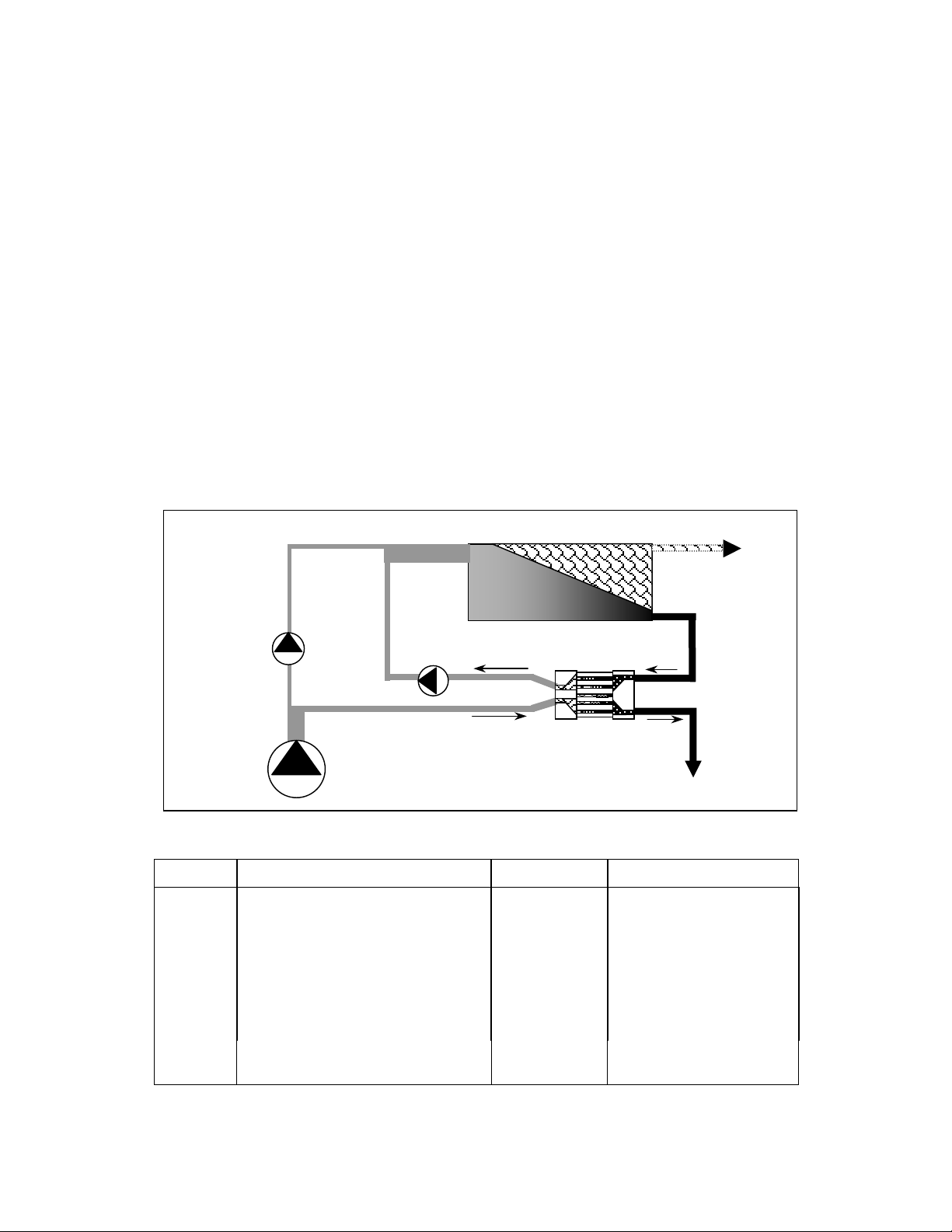
Figure 4-1 shows the flow path of a PX Booster Pump installed in a typical SWRO system
equipped with PX technology. The reject brine from the SWRO membranes (G) passes through
the PX unit(s) where its pressure is transferred directly to a portion of the incoming raw
seawater at up to 95% efficiency. This pressurized seawater stream (D), which is nearly equal
in volume and pressure to the reject stream, passes through the PX Booster Pump (not the
main high-pressure pump) to add the small amount of pressure lost to friction in the PX unit(s),
the membranes, and the associated piping. The PX Booster Pump is specially designed to
handle high operating pressures while consuming minimal energy to provide a small boost to
the high-pressure flow. The PX Booster Pump also serves to drive the flow of the high-
pressure stream through the PX unit(s) (G and D). Fully pressurized seawater then merges
with the main seawater to the SWRO system after the main high-pressure pump. Example flow
rates and pressures are listed in Table 4.1.
Figure 4-2. Typical SWRO System with PX Unit(s) and PX Booster Pump
Table 4-1 - Example Flow Rates and Pressures
STREAM DESCRIPTION FLOW RATE PRESSURE PSI / BAR
A Seawater supply 330 29 / 2.0
B PX LP Inlet/ Seawater 195 29 / 2.0
C Main HP Pump outlet 135 1000 / 69
D PX HP Outlet/ Seawater 195 957 / 66
E Booster Pump Outlet/ Seawater 195 1000 / 69
F SWRO Feed Stream 330 1000 / 69
G PX HP Inlet/ Reject 200 971 / 67
H PX LP Outlet/ Reject 200 15 / 1.0
I SWRO Product Water 130 5 / 0.3
B
PX Booster Pum
p
Main High
Pressure Pump
Seawater Supply
Pum
p
Permeate
Pressure
Exchanger(s)
F
H
G
I
E
A
C
D

SERIES 8500-2400 PX BOOSTER PUMPS
Energy Recovery, Inc. 6 ERI Document Number 80020-01-2
In an SWRO system equipped with PX technology, the main pump is sized to equal the SWRO
permeate flow plus a small amount of bearing lubrication flow, not the full SWRO feed flow.
Therefore, PX technology significantly reduces flow through the main pump. This point is
significant because a reduction in the size of the main pump results in lower operating costs. In
a typical SWRO system equipped with PX technology, the main pump will provide 41% of the
energy, the booster will provide 2% and the PX unit(s) will provide the remaining 57%. Since
the PX energy recovery device uses no external power, the total power savings is 57%
compared to a system with no energy recovery.
It is important to note that the PX unit(s) and associated boost pump are sized for 100% of the
reject flow. The role and size of the main high-pressure pump is reduced to that of a “make-up
pump” to compensate for the water that is exiting the SWRO system as permeate.
5.0 INSTALLATION
The PX Booster Pump should be installed in a dry, sheltered location. Some type of drainage
should be provided beneath the pump to allow standing water to drain when performing
maintenance or repair. See installation drawings in Section 13.0 for pump dimensions,
interface locations and minimum maintenance envelope requirements.
1. Place the PX Booster Pump in an appropriate location and mount the motor securely;
making sure that the base of the unit is permanently supported.
2. Connect the inlet and outlet of the pump to the appropriate points. Proper piping, piping
support, and motor mounts must be implemented to minimize external stresses on all piping
fittings. Flexible couplings should be used for joining fittings and piping. See Section 13.0
for appropriate connection dimensions and specifications. PX Booster Pumps are shipped
with the inlet oriented vertically upward. The inlet housing can be rotated either left or right
to a horizontal orientation. Remove the four (4) bolts that connect the inlet housing to the
yellow bell housing, rotate the pump head and replace the bolts. Torque bolts to 12 ft-lbs
(16 N-m) as shown in Figure 7-4 below.
3. Connect the pump motor to a suitable electrical supply. See the motor plate or the inside
cover of the motor electrical junction box for high and low voltage wiring diagrams. If no
wiring diagram is evident on the motor, refer to Table 5-1. Connect a suitable ground to the
pump motor.
The PX Booster Pump is constructed from AL6XN or
equivalent stainless steel. Inlet and discharge
interconnecting lines should be constructed of suitable
materials to avoid galvanic corrosion.
ERI encourages plant designers and engineers to submit P&IDs to ERI
for engineering review, especially for large or complex SWRO systems.
CAUTION
NOTE
SERIES 8500-2400 PX BOOSTER PUMPS
Energy Recovery, Inc. 7 ERI Document Number 80020-01-2
4. The SWRO-PX system must include pressure gauges upstream and downstream of the PX
Booster Pump and a high-pressure flow meter in the high-pressure circuit.
Table 5-1 – Motor Wiring
MOTOR
MANUFACTURER L1 L2 L3 JOIN
High Voltage 1 2 3 4+7, 5+8, 6+9
General Electric Low Voltage 1+7 2+8 3+9 4+5+6
High Voltage 1+12 2+10 3+11 4+7, 5+8, 6+9
Leeson Low Voltage 1+6+7+12 2+4+8+10 3+5+9+11 —
6.0 OPERATION
6.1 Specifications
The successful use of the PX Booster Pump depends on observing some basic operating
conditions and precautions. The PX Booster Pump must be installed, operated and maintained
in accordance with this manual and good industrial practice to assure safe operation and a long
service life. Failure to observe these conditions and precautions can result in violation of the
warranty, damage to the equipment, and/or harm to personnel.
Disconnect electrical supply before installing and/or
servicing the pump. Failure to do so can cause serious
injury or death to personnel.
Strictly observe all applicable electrical codes and
regulations governing the installation and wiring of electrical
equipment.
The power supply should always be of a greater service rating than
the requirements of the pump. Never connect the pump to a line
that services another electrical device. The pump should have
dedicated power circuit with proper fuse or breaker protection.
The PX Booster Pump is designed to be used in conjunction with a
variable frequency drive and high-pressure flow meter.
Check for proper motor rotation upon start up.
CAUTION
NOTE
NOTE
NOTE
Piping must be independently supported. Do not allow
piping to place a load on the PX Booster Pump.
CAUTION

SERIES 8500-2400 PX BOOSTER PUMPS
Energy Recovery, Inc. 8 ERI Document Number 80020-01-2
6.1.1 System Performance Specifications
Table 6-1 provides a summary of system performance specifications. See Section 12.0 for flow
and pressure curves.
Table 6-1 - System Performance Specifications
Parameter Specification
Raw Water Tem
p
erature Ran
g
e: 33-113°F
(
1-43°C
)
Maximum Outlet Pressure: 1200 psi / 83 bar
Minimum Inlet Pressure: 15 psi / 1.0 bar
Design Flow Range: *
HP-8503 30-110 gpm (7 – 25 m3/hr)
HP-8504 30-110 gpm (7 – 25 m3/hr)
HP-1253 40-190 gpm (9 – 43 m3/hr)
HP-1254 40-190 gpm (9 – 43 m3/hr)
HP-2402 80-300 gpm (18 – 68 m3/hr)
HP-2403 80-300 gpm (18 – 68 m3/hr)
* 60 Hz / 3450 rpm
6.1.2 Precautions and Conditions
The following precautions / conditions apply:
Piping connections to the pump must be designed so as not to induce stress on the pump or
motor.
Ensure that all flexible connections are secure and tight before operating pump.
Under no circumstances shall the inlet pressure or outlet pressure exceed 1,200 psig (83
bar).
Ensure sufficient feed water supply. The PX Booster Pump should be thoroughly purged of
air before startup. Operating the PX Booster Pump with feed pressures less than 15 psi may
result in damage to PX Booster Pumps internal components. Never run pump dry.
6.1.4 Physical Characteristics
See Section 13.0 for weights and dimensions. Connections dimensions and requirements are
provided in Table 6-2.
Do not allow the high-pressure reject and/or seawater to
exceed 1,200 psi (83 bar). If necessary, install a pressure
switch and/or safety valve in the high-pressure line(s) to
ensure the s
y
stem does not exceed 1,200 psi
(
83 bar
)
.
CAUTION Allowable operating ranges for individual PX Booster
Pumps are listed in Table 6-1. PX Booster Pumps are not
designed to operate outside of these ranges.

SERIES 8500-2400 PX BOOSTER PUMPS
Energy Recovery, Inc. 9 ERI Document Number 80020-01-2
Table 6-2 - Connection Dimensions and Requirements
Utility Connection Maximum Pressure (psi / bar)
Inlet 3” Flexible Coupling 1,200 / 83
Discharge 3” Flexible Coupling 1,200 / 83
6.1.5 Utility Requirements
Power requirements are provided on the nameplate on the top of all PX Booster Pump motors.
Horsepower requirements are provided in Table 6-3.
Table 6-3 – Motor Horsepower Requirements
HP-8503 HP-8504 HP-1253 HP-1254 HP-2402 HP-2403
5 7.5 10 15 15 20
6.1.6 Spare Parts
A listing of recommended ERI spare parts is provided in Table 6-4. O-ring kits are
recommended for disassembly and inspection. Rebuilt kits provide impellers, stage assemblies
and O-rings.
Table 6-4 - Recommended Spare Parts
DESCRIPTION QTY
O-RING KIT
PART NUMBER
REBUILD KIT
PART NUMBER
MECHANICAL
SEAL KIT
HP-8503 1 20005-02 20005-01* 20004-01
HP-8504 1 20006-02 20006-01* 20004-01
HP-1253 1 20007-02 20007-01* 20004-01
HP-1254 1 20008-02 20008-01* 20004-01
HP-2402 1 20009-02 20009-01* 20004-01
HP-2403 1 20010-02 20010-01* 20004-01
* Includes Impellers, Stage Assemblies and O-rings
6.2 Startup Procedure
Refer to the PX Operations and Maintenance manual for detailed startup and shutdown
instructions for the PX device.
1. Verify system is de-energized and un-pressurized.
2. Check tightness of all lines and fittings.
3. Supply feed water to the SWRO system and the PX unit’s low-pressure inlet.
Only genuine ERI spare parts should be used in PX Booster
Pumps. Use of parts other than those specified by ERI will void
the warranty.
NOTE

SERIES 8500-2400 PX BOOSTER PUMPS
Energy Recovery, Inc. 10 ERI Document Number 80020-01-2
4. Verify that the inlet pressure to the PX Booster Pump is at least 15 psi as seen at the inlet of
the main high-pressure pump. Verify that all air has been purged from the system. The
pump cannot be run dry for even a few seconds. Damage will occur in seconds if the pump
is started dry.
5. Jog the PX Booster Pump and verify that its rotation is correct.
6. Start the PX Booster Pump and verify that the pump is operating on the flow and pressure
curves provided in Section 12.0.
6.3 Maintenance and Startup Log
A sample operating-log has been provided in Section 8.0 of this manual and must be submitted
by fax or e-mail to Energy Recovery, Inc. in San Leandro, California upon completion of the
startup and flow balancing routines. Submittal of this form with the initial startup data within
24 hours of startup is a condition of obtaining PX Booster Pump warranty coverage. The data
must be recorded daily and maintained during the life of the warranty in order to support any
claims. Include pump serial number with all submittals.
Submittal of the maintenance and startup log to ERI within 24 hours of startup is a condition of
obtaining PX Booster Pump warranty coverage. The data must be recorded daily and
maintained during the life of the warranty in order to support any claims.
7.0 MAINTENANCE INSTRUCTIONS
7.1 General
The table below details the specific recommended pump maintenance requirements for the
ERI’s PX Booster Pump product line:
Never run the PX Booster Pump dry or with low feed flow.
Operating with feed pressures less than 15 psi (1 bar) or below
recommended the flow range can cause damage to the pump’s
internal components.
The PX Booster Pump should rotate in the clockwise direction when
facing the rear of the motor.
A sample operating-log has been provided at the end of Section 8.0
and must be submitted by fax or e-mail to Energy Recovery, Inc.
upon completion of the startup and balancing routines. Submittal of
this form with the initial startup data within 24 hours of startup is a
condition of obtaining warranty coverage. The data must be
recorded daily and maintained during the life of the warranty in
order to support any claims. Include serial number with submittal.
CAUTION
NOTE
NOTE

SERIES 8500-2400 PX BOOSTER PUMPS
Energy Recovery, Inc. 11 ERI Document Number 80020-01-2
Table 7-1 - Periodic Maintenance Task Frequency
Weekly
3 Months
As Required
Labor Hours
(approximate)
Inspect connections 0.1
Inspect mechanical seal 0.1
Lubricate pump motor 0.2
Change mechanical seal 2.0
7.2 Lubricate PX Booster Pump Motor
Motor bearings should be checked daily for temperature and noise. Motor bearings must be
lubricated a minimum of every three months. Use a grease gun and high-quality ball bearing
grease such as Shell Dolium R or Chevron SR1 2. Refer to the motor manufacturer’s websites
for additional guidance and information.
7.3 Mechanical Seal Maintenance
A mechanical seal is used to seal the rotating shaft. This seal will require replacement
approximately every 12-18 months. An indication that maintenance is required will be a leak or
drip from the rear of the pump into the bell housing. Mechanical seal kits are available from
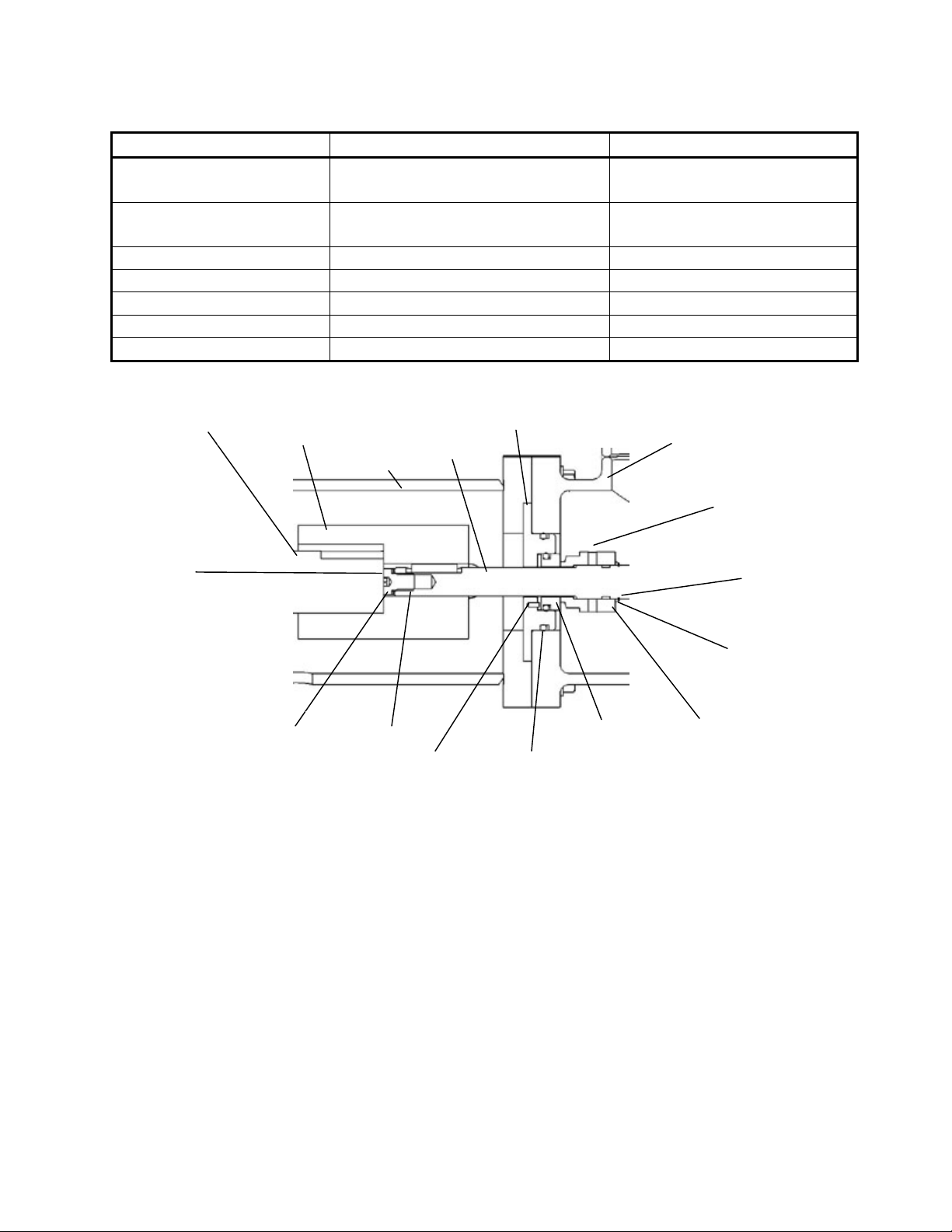
ERI. The kit includes the components listed in Table 7-2 and illustrated in Figure 7-1.
Table 7-2 - Mechanical Seal Kit - ERI Part Number 20004-01
PART NUMBER DESCRIPTION QUANTITY
10055-01 SHIM 2
10066-01 RETAINING RING, 3 /4” 1
10117-01 DOWEL PIN 2
10122-01 SPACER 1
10123-01 MECHANICAL SEAL 1
10124-01 FENDER WASHER 2
10128-01 ALLEN WRENCH, 3/32” 1
10134-01 THREAD LOCKER 1
10160-01 O-RING, -225 1
80027-01 MECHANICAL SEAL O&M MANUAL 1
ERI offers a tool kit (ERI Part Number 20003-01) for PX Booster Pump maintenance
operations. Alternately, a list of tools and materials recommended for maintenance of the
mechanical seal are provided in Table 7-3.
SERIES 8500-2400 PX BOOSTER PUMPS
Energy Recovery, Inc. 12 ERI Document Number 80020-01-2
Table 7-3 - Recommended Tools and Materials
Pump Model Tool Application
all 9/16-inch Wrench
Bolts between Inlet Housing
and Bell Housing
all 3/4-inch Wrench
Bolts between Bell Housing
and Motor
8500-pumps 3/16-inch Allen/Hex Wrench Coupling
1250- and 2400-pumps 1/4-inch Allen/Hex Wrench Coupling
all 3/32-inch Allen/Hex Wrench Seal Set Screws
all Anti-Seize Compound All Threads
all Water Soluble Lubricant O-Rings
The following procedure provides instructions for removing an old seal and inserting a new
one.
7.3.1 Remove the Old Mechanical Seal
1. Verify system is de-energized and un-pressurized.
2. Disconnect the flexible coupling connections from the inlet and outlet of the PX Booster
Pump and allow water to drain from system.
3. Unbolt the motor base from the floor.
4. Stand the PX Booster Pump on the motor in a vertical orientation as shown in Figure 7-2.
5. Partially loosen (1-3 turns) the eight (8) shaft coupling screws inside the bell housing.
There is an access slot for these screws at the side of the bell housing. See Figure 7-3.
6. Remove the four bolts that hold the inlet housing to the bell housing with a 9/16” wrench
as shown in Figure 7-4.
Figure 7-1 - Section View of Shaft and Seal Components
Motor
Shaft Coupling Bell
Housing Pump
Shaft Seal
Plate
Jack
Screw
Stationary
Seal Primary
Seal
Window to
check
Compression
shafts in
contact
Inlet
Housing
Pin O-Ring
Spacer
10122-01
Retaining
Rin
g
Shim
Spacer(s)
10055-01

SERIES 8500-2400 PX BOOSTER PUMPS
Energy Recovery, Inc. 13 ERI Document Number 80020-01-2
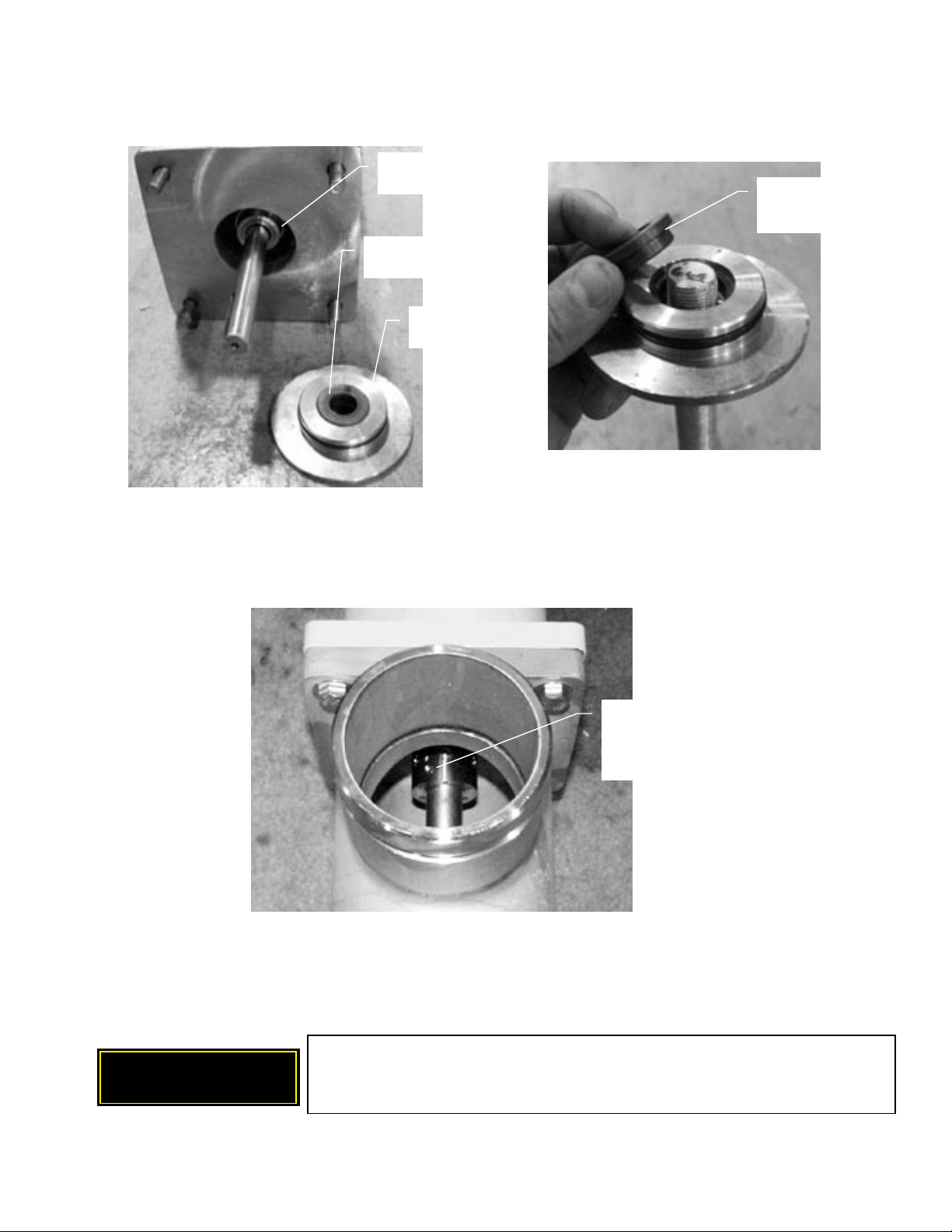
7. Pull the pump, shaft and seal out of the bell housing and away from the motor.
8. Remove the seal plate from the inlet housing as shown in Figure 7-5. It may be necessary
to pull on the pump shaft to create an initial gap between the seal plate and the inlet.
9. The mechanical seal includes the primary seal and the stationary or mating plate as shown
in Figure 7-6. Extract the stationary plate from the seal plate by pushing through the seal
plate with a rod as shown in Figure 7-7. Remove stationary plate from the seal plate.
Bell Housing
Coupling Screws (4x2)
Figure 7-3 - Loosen Coupling Screws
Access Slot
Figure 7-2 - Pump
Oriented Vertically
Figure 7-5 - Remove Seal Plate from InletFigure 7-4 - Remove Pump from Bell Housing
SERIES 8500-2400 PX BOOSTER PUMPS
Energy Recovery, Inc. 14 ERI Document Number 80020-01-2
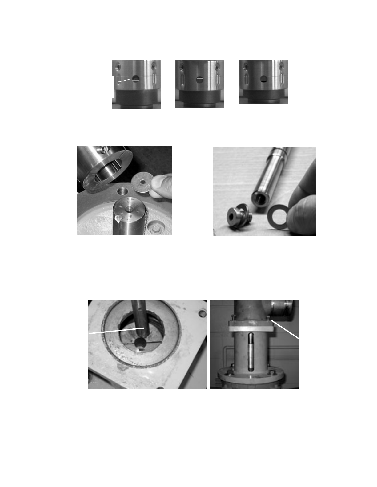
10. Loosen the four (4) set screws (3/32 inch hex) that hold the primary seal onto the shaft as
shown in Figure 7-8. Be careful not to strip the set screws. If a particular set screw is very
tight, it may be necessary to rotate the shaft and loosen a different set screw first.
11. Slide the primary seal off the shaft and out of the pump.
12. Remove the bell housing from the motor as shown in Figure 7-9.
13. Remove the coupling from the motor shaft. Disassemble the coupling as shown in Figure 7-
10. Clean the coupling and the shaft keys to remove any salt deposits or debris.
Mechanical seal set
screw, 4ea,
3/32 inch hex
Figure 7-8 - Loosen Set Screws
Primary Seal
Stationary Plate
Seal Plate
Figure 7-6 - Mechanical Seal Components
Stationary
Plate
Figure 7-7 - Extract Stationary
Plate from Seal Plate
Keep the shafts and coupling clean and free of dirt, rust and foreign
matter. Use plenty of anti-seize upon reassembly to ensure easy
disassembly the next time.
CAUTION

SERIES 8500-2400 PX BOOSTER PUMPS
Energy Recovery, Inc. 15 ERI Document Number 80020-01-2
7.3.2 Install the New Mechanical Seal
Before installing the new mechanical seal, completely remove the pump head, the bell housing
and the coupling as described above.
1. Reassemble the coupling using plenty of antiseize on the bolts and inside of the coupling.
Apply antiseize to the motor shaft.
2. Install the coupling onto the motor shaft as shown in Figure 7-11. Use plenty of antiseize.
3. Install the bell housing onto the motor as shown in Figure 7-11. Use anti-seize compound
on the bolt threads. Make sure that the drainage hole is oriented so that it will be on the
bottom of the bell housing when the PX Booster Pump is reinstalled. Torque the bolts to 40
foot-pounds (ft-lbs) / 58 N-m.
Figure 7-9 - Remove Bell Housing
Figure 7-10 - Disassemble Coupling and Clean Components

SERIES 8500-2400 PX BOOSTER PUMPS
Energy Recovery, Inc. 16 ERI Document Number 80020-01-2
Figure 7-11 – Install Coupling and Bell Housing onto Motor
4. Lubricate the o-ring in the new primary seal with a water-soluble lubricant. Install new
spacer ring and new primary seal onto the pump shaft. Slide these components onto the
shaft until they contact the retaining ring. See Figure 7-12 and 7-13 for the correct
sequence. Tighten the three set screws to 7 inch-pounds (in-lbs) / 0.79 Newton-meters (N-
m) torque using a 3/32-inch hex wrench.
5. Insert the anti-rotation pin into the seal plate as shown in Figure 7-14. Once inserted, the
pin should not protrude more than 1/16-inch (1.6 mm). Assure that there is no debris inside
the seal plate that would prevent the stationary seal from fully seating.
6. Lubricate the O-ring of the new stationary seal with a water-based lubricant such as
glycerin or soap. Insert the new stationary seal into the seal plate. Be sure to line up the
groove in the bottom of the stationary ring with the anti-rotation pin as shown in Figure 7-
15. The stationary seal must seat flat and level in the seal plate.
Shaft
Figure 7-12 - Primary Seal Sequence
Primary
Seal
Set Screw
Groove
Retaining
Ring
Spacer
Figure 7-13 - Primary Seal Assembly
Retaining
Ring
Primary
Seal
Set
Screw (4)
Spacer
Drainage Hole

SERIES 8500-2400 PX BOOSTER PUMPS
Energy Recovery, Inc. 17 ERI Document Number 80020-01-2
7. Slide the seal plate onto the shaft as shown in Figure 7-16.
Figure 7-16 – Assemble the Shaft, Seal and Seal Plate, Install into Inlet Housing
8. Align the shaft key with the slot in the coupling and install the pump onto the bell housing
as shown in Figure 7-17.
Figure 7-17 – Install Pump into Bell Housing
Figure 7-14 - Insert Anti-Rotation Pin Figure 7-15 - Stationary Seal, Line up Pin
with Groove
Groove
Pi
n
Antiseize
Key
Align shaft
key with slot
in coupling
Finger tight

SERIES 8500-2400 PX BOOSTER PUMPS
Energy Recovery, Inc. 18 ERI Document Number 80020-01-2
9. Assemble the seal compression tool components using a flexible coupling as shown in
Figure 7-18. Alternately, compress seal manually as shown in Figure 7-19.
Figure 7-18 – Assemble and Install Seal Compression Tool Components
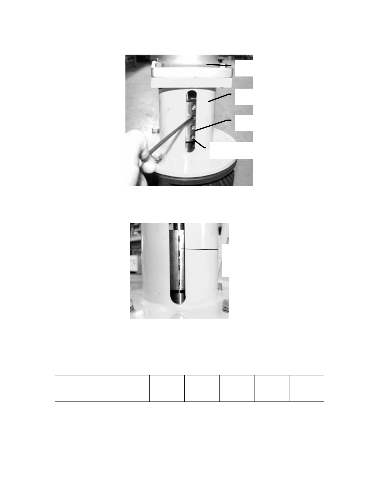
10. Check the seal compression by applying downward force on the pump shaft while looking
into the inlet housing as shown in Figure 7-19.
Figure 7-19 – Install Pump onto Bell Housing
11. Inspect the mechanical seal inside the inlet housing. Check the compression of the
mechanical seal by looking into the circular window as shown in Figure 7-20. If seal is not
correctly compressed, remove the pump and install a fender washer into the shaft coupling
or a shim spacer onto the shaft as shown in Figure 7-21. Reassemble pump according to the
steps above.
Apply downward force
to top of shaft
Check seal compression
SERIES 8500-2400 PX BOOSTER PUMPS
Energy Recovery, Inc. 19 ERI Document Number 80020-01-2
12. Verify that the shaft keys are in place.
13. Line up the key of the pump shaft with the slot in the shaft coupling inside the bell housing
as shown in Figure 7-22 below.
14. Install the pump head onto the bell housing. Install the four (4) bolts between the pump to
finger tight.
Figure 7-22 – Install Pump into Bell Housing
15. With the pump and motor shafts in contact, tighten the eight (8) coupling screw as shown
in Figure 7-23. NOTE: THE PUMP AND MOTOR SHAFT MUST BE IN CONTACT.
Figure 7-21 – Add or Remove Fender Washer(s) or Shim Spacer(s) to Change Seal Compression
Figure 7-20 - Check Seal Compression
Circular Window to
Check Compression
Under
Compressed Correct
Compression Over
Compressed
Align shaft
key with slot
in coupling
Finger tight
SERIES 8500-2400 PX BOOSTER PUMPS
Energy Recovery, Inc. 20 ERI Document Number 80020-01-2
16. Tighten both halves of the coupling evenly making sure that the gap between the two halves
is equal as shown in Figure 7-24.
17. Torque the coupling screws according to the requirements listed in Table 7-4. Make sure
the gap between the two halves of the coupling is even on both sides as shown in Figure 7-
24. The coupling must be tightened evenly and fully to prevent an out of balance condition,
excessive vibration and premature motor bearing failure.
Table 7-4 - Shaft Coupling Torque Requirements
HP-8503 HP-8504 HP-1253 HP-1254 HP-2402 HP-2403
Coupling Screw
Torque
8 ft-lb /
11 N-m
8 ft-lb /
11 N-m
8 ft-lb /
11 N-m
8 ft-lb /
11 N-m
12 ft-lb /
16 N-m
12 ft-lb /
16 N-m
Figure 7-24 - Check Gap Between Coupling Halves
Gap – Both
sides equal
gap
Bell Housing
Coupling Screws (4x2)
Figure 7-23 – Tighten Coupling onto Shafts
Access Slot
Inlet Housing
This manual suits for next models
7
Table of contents
Popular Water Pump manuals by other brands

Rosenbauer
Rosenbauer R600 Operation manual

Fuelab
Fuelab 42401-c Operating and installation instructions

Barmesa Pumps
Barmesa Pumps BSP-CCE Series Installation, operation & maintenance manual

Fimco
Fimco High-Flo HFP-45060-113 owner's manual

CAT Pumps
CAT Pumps 2530 Service manual

AquaScape
AquaScape AquaJet 600 Instruction and maintenance

Crane
Crane BARNES SP33HTX Series installation manual

Dover
Dover PSG ALL-FLO MAX-PASS S Series Installation, Operation & Maintenance Instruction Manual

Walrus
Walrus TPK Series Replacing

T.I.P.
T.I.P. GPK 46/42 operating instructions

Lavor
Lavor EDP 5000 Translation of the original instructions

Oase
Oase AquaMax Eco Expert 21000 Commissioning


