Energy Star 355-5952 User manual

52” Energy Select Ceiling Fan
Owner’s Manual
Ventilador de Techo de 132.1cm
Manual del Propietario
SKU 355-5952
LISTED

52” Energy Select Ceiling Fan
QUESTIONS, PROBLEMS, MISSING PARTS:
Please do not return to retailer: Call 1-800-749-3267 for any missing parts or
questions regarding installation.
Please reference your SKU (355-5952 white)
or UPC (082392 636012 white).
Safety Rules.................................1
Unpacking Your Fan....................2
Installing Your Fan ......................3
Operating Your Fan .....................10
Care of Your Fan..........................11
Troubleshooting ..........................11
Specications ..............................12
Warranty Information ..................13
Table of Contents
UL Model No.: EF200M(C)-52
1. To reduce the risk of electric shock, insure electricity
has been turned off at the circuit breaker or fuse box
before beginning.
2. All wiring must be in accordance with the National
Electrical Code ANSI/NFPA 70-1999 and local electrical
codes. Electrical installation should be performed by a
qualied licensed electrician.
3. WARNING: To reduce the risk of re or electrical shock,
do not use this fan with any solid-state fan speed con-
trol device.
4. CAUTION: To reduce the risk of personal injury, use
only the screws provided with the outlet box.
5. The outlet box and support structure must be securely
mounted and capable of reliably supporting a minimum
of 35 pounds. Use only UL Listed outlet boxes marked
“FOR FAN SUPPORT.”
6. The fan must be mounted with a minimum of 7 feet
clearance from the trailing edge of the blades to the
oor.
7. Do not operate reversing switch while fan blades are in
motion. Fan must be turned off and blades stopped be-
fore reversing blade direction.
8. Avoid placing objects in path of the blades.
9. To avoid personal injury or damage to the fan and
other items, be cautious when working around or
cleaning the fan.
10. Do not use water or detergents when cleaning the fan
or fan blades. A dry dust cloth or lightly dampened cloth
will be suitable for most cleaning.
11. After making electrical connections, spliced conductors
should be turned upward and pushed carefully up into
outlet box. The wires should be spread apart with the
grounded conductor and the equipment-grounding
conductor on one side of the outlet box.
12. Electrical diagrams are for reference only. Light kits
that are not packed with the fan must be UL listed and
marked suitable for use with the model fan you are in-
stalling. Switches must be UL general use switches.
Refer to the instructions packaged with the light kits
and switches for proper assembly.
13. All set screws must be checked and tightened where
necessary before installation.
Safety Rules 1.
READ AND SAVE THESE INSTRUCTIONS
TO REDUCE THE RISK OF FIRE, ELECTRIC SHOCK OR PERSONAL
INJURY, MOUNT FAN TO OUTLET BOX MARKED “ACCEPTABLE
FOR FAN SUPPORT” WITH THE SCREWS PROVIDED WITH THE
OUTLET BOX. MOST OUTLET BOXES COMMONLY USED FOR THE
SUPPORT OF LIGHTING FIXTURES ARE NOT ACCEPTABLE FOR FAN
SUPPORT AND MAY NEED TO BE REPLACED. CONSULT A QUALIFIED
ELECTRICIAN IF IN DOUBT.
TO REDUCE THE RISK OF PERSONAL INJURY, DO NOT BEND THE
BLADE BRACKETS (ALSO REFERRED TO AS “FLANGES”) DURING
ASSEMBLY OR AFTER INSTALLATION. DO NOT INSERT OBJECTS IN
THE PATH OF THE BLADES.
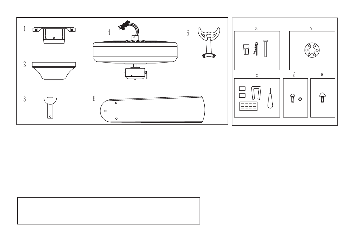
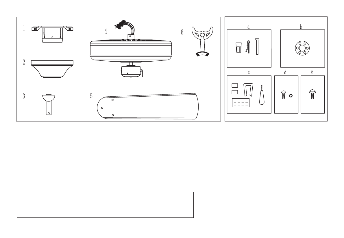
a. Electrical & Mounting Hardware
(3 plastic wire connectors, 1 hanger
pin, 1 locking pin)
b. Close-to-Ceiling Mount Hardware
(1 Rubber Gasket)
c. Miscellaneous Parts
(Blade Balancing Kit, 1 Pull Chain
for the Fan)
d. Extra Blade Bracket Hardware
(1 screw and lockwasher)
e. Blade Attachment Hardware
(15 screws)
6. Blade Brackets (5)1. Slide-On Mounting Plate (inside canopy)
2. Canopy
3. Downrod and Hanger Ball Assembly
4. Fan Motor Assembly
5. Blades (5)
2. Unpacking Your Fan
IMPORTANT: THIS PRODUCT AND/OR COMPONENTS ARE COVERED
BY ONE OR MORE OF THE FOLLOWING U.S. PATENTS: 5,947,436;
5,988,580; 5,971,573; 6,010,306; 6,039,541; 6,046,416 AND OTHER
PATENTS PENDING.
Unpack your fan and check the contents. You should have the following items:
Installing Your Fan 3.
Tools Required
Phillips screw driver, straight slot screw
driver, adjustable wrench, step ladder,
and wire cutters.
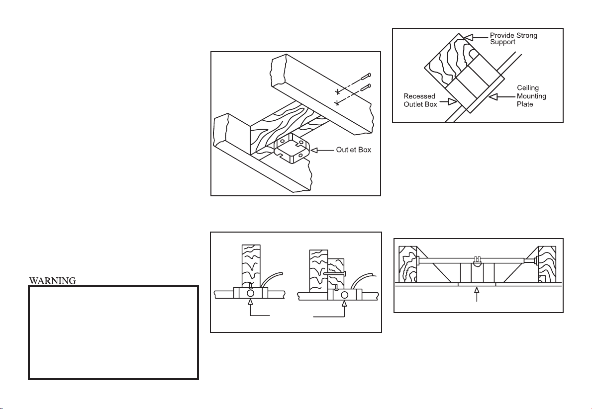
Mounting Options
Ifthereisn’tanexistingoutlet box,thenread
the following instructions. Disconnect the
power by removing fuses or turning off
circuit breakers.
Secure the outlet box directly to the building
structure. Use appropriate fasteners and
building materials. The outlet box and its
support must be able to fully support the
moving weight of the fan (at least 35 lbs.)
Do not use plastic outlet boxes.
Figures 1, 2, and 3 are examples of differ-
ent ways to mount the outlet box.
Outlet Box
Note: You may need a longer downrod to
maintain proper blade clearance when
installing on a steep, sloped ceil-
ing. The maximum angle allowable
is 30˚. If the canopy touches down-
rod, remove the decorative canopy
bottom cover and turn the canopy 180˚
before attaching the canopy to the
mounting plate.
Outlet Box
To hang your fan where there is an existing
xture but no ceiling joist, you may need
an installation hanger bar as shown in
Figure 4.
TO REDUCE THE RISK OF FIRE, ELECTRIC
SHOCK OR PERSONAL INJURY, MOUNT
FAN ONLY TO AN OUTLET BOX MARKED
ACCEPTABLE FOR FAN SUPPORT AND
USE THE MOUNTING SCREWS PROVIDED
WITH THE OUTLET BOX. OUTLET BOXES
COMMONLY USED FOR THE SUPPORT OF
LIGHTING FIXTURES MAY NOT BE ACCEPT-
ABLE FOR FAN SUPPORT AND MAY NEED TO
BE REPLACED. CONSULT A QUALIFIED ELEC-
TRICIAN IF IN DOUBT.
Figure 1
Figure 2
Figure 4
Figure 3
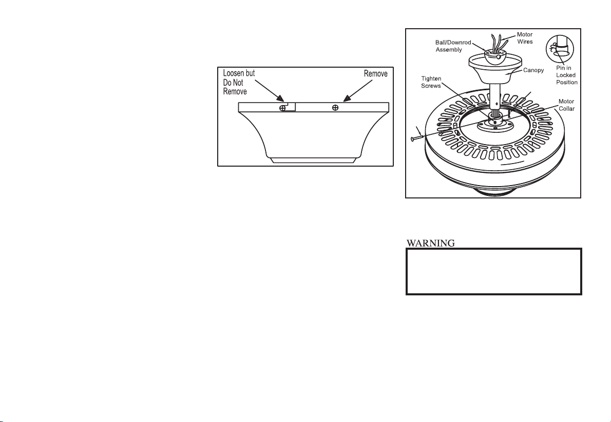
two non-slotted screws and loosen the
slotted screws. This will enable you to
remove the mounting plate (Figure 5).
2. Route the wires exiting the top of the
fan motor through the canopy and then
through the ball/downrod assembly
(Figure 6).
3. Loosen, but do not remove the set
screws on the collar on top of the mo-
tor housing.
4. Align the holes at the bottom of the
downrod with the holes in the collar
on top of the motor housing (Figure
6). Carefully insert the bolt through the
holes in the collar and downrod. Be
careful not to jam the bolt against the
wiring inside the downrod. Insert clevis
pin and bend to ensure security, as
noted in circle inset of Figure 6.
5. Re-tighten the two screws on the collar
on the top of the motor housing (Figure
6).
4.
Hanging the Fan
REMEMBER to turn off the power.
Follow the steps below to hang your
fan properly.
NOTE: This ceiling fan is supplied with two
types of hanging assemblies; the standard
ceiling installation using the downrod with
ball and socket mounting, and the “close-
to-ceiling” mounting. The “close-to-ceiling”
mounting is recommended in rooms with
less than 8-foot ceilings or in areas where
additional space is desired from the oor
to the fan blades. When using standard
downrod installation, the distance from the
ceiling to the bottom of the fan blades will be
approximately 11 inches. The “close-to-ceil-
ing” installation reduces the distance from
the ceiling to the bottom of the fan blades to
approximately 8 inches.
Once you have decided which ceiling
installation you will use, proceed with the
following instructions. Where necessary,
each section of the instructions will note the
different procedures to follow for the two
types of installation.
Standard Ceiling
Mounting
1. Remove the mounting plate from the
canopy by loosening the four screws
on the top of the canopy. Remove the
Figure 5
FAILURE TO PROPERLY INSTALL LOCKING PIN
AS NOTED IN STEP 4 AND PROPERLY TIGHTEN
SET SCREWS AS NOTED IN STEP 5 COULD
RESULT IN FAN LOOSENING AND POSSIBLY
FALLING.
Figure 6
Bolt
Clevis Pin
6. Proceed to “Installing The Fan” section.

4. Place the rubber gasket over the
remaining three screws, route the wires
exiting the top of the fan motor through
the canopy ring (make sure the slot
openings are on top), then proceed to
place the ceiling canopy over the collar
at the top of the motor (Figure 9).
5. Align the mounting holes with the holes
in the motor and fasten, using the three
screws and lock-washers removed in
step 3 (Figure 9).
6. Tighten the mounting screws securely.
5.
Figure 8
“Close-to-Ceiling”
Mounting
1. Remove the mounting plate from the
canopy by loosening the four screws on
the top of the canopy. Remove the two
non-slotted screws and loosen the slotted
screws. This will enable you to remove the
mounting plate (Figure 5).
2. Remove the decorative canopy bottom
cover from the canopy by depressing
the three studs (Figure 7).
3. Remove three of the six screws and lock
washers (every other one) securing the
reinforcing plate to the top of the fan mo-
tor housing (Figure 8).
(3 of 6 Screws)
Figure 9
(3 Screws)
FAILURE TO COMPLETELY TIGHTEN THE
THREE SCREWS IN STEP 6 COULD RESULT IN
FAN LOOSENING AND POSSIBLY FALLING.
Figure 7
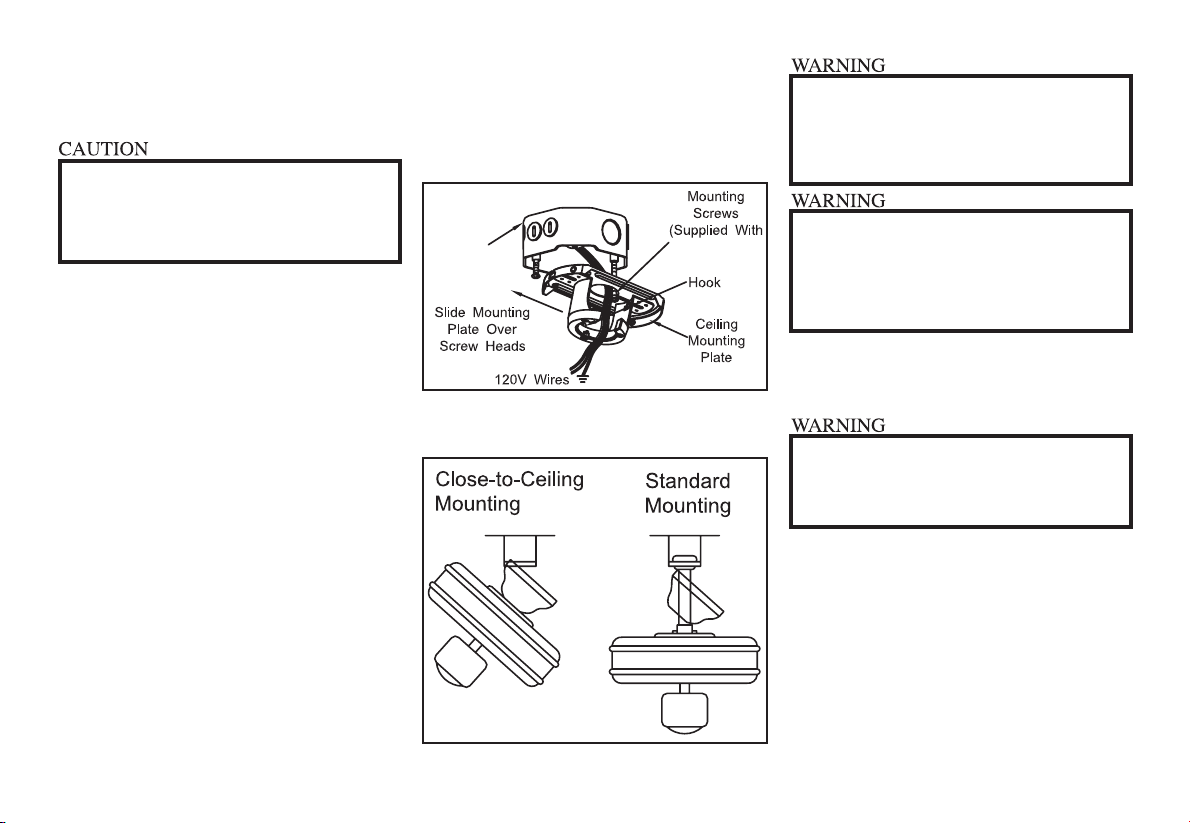
1. Pass the 120-volt supply wires through
the center hole in the ceiling mounting
plate as shown in Figure 10.
2. Install the ceiling mounting plate on
the outlet box, by sliding the mounting
plate over the two screws provided with
the outlet box (Figure 10). When using
close-to-ceiling mounting, it is important
that the mounting plate be level. If
necessary, use leveling washers (not
included) between the mounting plate
and the outlet box. Note that the at
side of the mounting plate is toward the
outlet box (Figure 10).
3. Securely tighten the two mounting
screws.
4. Carefully lift the assembly up to the
ceiling mounting plate and hang the fan
on the hook provided by utilizing one of
the holes at the outer rim of the ceiling
canopy (Figure 11). If using standard
UL Listed
Outlet Box Outlet Box)
Figure 11
Figure 10
THE HOOK AS SHOWN IN FIGURE 11 IS ONLY
TO BALANCE FAN WHILE ATTACHING WIRING.
FAILURE TO HANG AS SHOWN IN FIGURE 11
MAY RESULT IN HOOK BREAKING, CAUSING
THE FAN TO FALL. HOOK MUST PASS FROM
INSIDE TO OUTSIDE OF CANOPY.
WHEN USING THE STANDARD BALL/
DOWNROD MOUNTING, THE TAB IN THE RING
AT THE BOTTOM OF THE MOUNTING PLATE
MUST REST IN THE GROOVE OF THE HANGER
BALL FAILURE TO PROPERLY SEAT TAB IN
THE GROOVE COULD CAUSE DAMAGE TO THE
WIRING.
TO REDUCE RISK OF FIRE OR ELECTRIC
SHOCK, DO NOT USE A SOLID STATE
SPEED CONTROL WITH THIS FAN. IT WILL
PERMANENTLY DAMAGE THE ELECTRONIC
CIRCUITRY.
6.
Making the Electrical
Connections
REMEMBER to disconnect the power. If
you feel you do not have enough electrical
wiring knowledge or experience, have your
fan installed by a licensed electrician.
Follow the steps below to connect the fan
to your household wiring. Use the wire
connecting nuts supplied with your fan.
Secure the connectors with electrical tape.
Make sure there are no loose strands or
connections.
WHEN MOUNTING THE FAN ON A SLOPED
CEILING, THE STANDARD BALL/DOWNROD
MOUNTING METHOD MUST BE USED. MAKE
SURE THE MOUNTING PLATE SLOTS ARE ON
THE LOWER SIDE BY SLIDING THE MOUNTING
PLATE FROM THE TOP DOWN.
Installing Fan to the
Electrical Box
mounting, seat the hanger ball in the
mounting plate socket. Make sure the
tab on the mounting plate socket is
properly seated in the groove in the
hanger ball (Figure 11).
Installing Fan to the
Electrical Box

7.
Outlet Box
ELECTRICAL DIAGRAMS ARE FOR
REFERENCE ONLY. OPTIONAL USE OF ANY
LIGHT KIT SHALL BE UL LISTED AND MARKED
SUITABLE FOR USE WITH THIS FAN.
Figure 12
1. Connect the ground conductor of the
120v supply (this may be a bare wire or
a wire with green insulation) to the green
ground lead(s) of the fan (Figure 12).
When using standard ceiling mounting,
there are two green grounding leads;
one from the ceiling mounting plate and
one from the ball/downrod assembly.
When using Close-to-Ceiling mount-
ing, there is only one green ground lead
from the mounting plate since the ball/
downrod assembly is not used.
2. Connect the fan motor white wire to the
supply white (neutral) wire using a wire
nut (Figure 12).
3. Connect the fan motor black wire to the
supply black (hot) wire using a wire nut
(Figure 12).
4. Turn wire connections upward, spread-
ing them apart so the green (ground)
and white wires will be on one side of
the outlet box and the black and blue
wires will be on the other side, and push
into the outlet box.
EACH WIRE NUT (WIRE CONNECTOR)
SUPPLIED WITH THIS FAN IS DESIGNED
TO ACCEPT UP TO ONE 12 GAUGE
HOUSE WIRE AND TWO WIRES FROM
THIS FAN. IF YOU HAVE LARGER THAN 12
GAUGE HOUSE WIRING OR MORE THAN
ONE HOUSE WIRE TO CONNECT TO THE
FAN WIRING, CONSULT AND ELECTRI-
CIAN FOR THE PROPER SIZE WIRE NUTS
TO USE.

8.
Attaching the
Fan Blades
NOTE: Your fan blades are reversible. Se-
lect the blade nish which best accentuates
you decor.
1. Attach blade to blade bracket using the
screws provided as shown in gure 13.
Please note that the rubber washers are
pre-attached to the blade bracket. Insert
a screw into the bracket. Repeat for the
two remaining screws.
2. Tighten each screw securely.
3. Fasten the blade assembly to the motor
by inserting the alignment post into the
slot on the bottom of the motor and tight-
ening the motor screws. Please note
that the motor screws are pre-attached
into the blade bracket (Figure 14).
4. Repeat steps 1-3 for the remaining
blades.
1. Align the locking slots of the ceiling
canopy with the two screws in the
mounting plate. Push up to engage the
slots and turn clockwise to lock in place.
Immediately tighten the two mounting
screws rmly.
2. Install the remaining two mounting
screws into the holes in the canopy and
tighten rmly.
3. You may now proceed to attaching the
fan blades.
CLOSE-TO-CEILING MOUNTING
1. Carefully unhook the fan from the
mounting plate and align the locking
slots of the ceiling canopy with the two
screws in the mounting plate. Push up
to engage the slots and turn clockwise
to lock in place. Immediately tighten the
two mounting screws rmly.
LOCKING SLOTS OF CEILING CANOPY ARE
PROVIDED ONLY AS AN AID TO MOUNTING.
DO NOT LEAVE FAN ASSEMBLY UNATTENDED
UNTIL ALL FOUR CANOPY SCREWS ARE
ENGAGED AND FIRMLY TIGHTENED.
Figure 13
Figure 14
2. Install the remaining two mounting
screws into the holes in the canopy and
tighten rmly.
3. You may now proceed to attaching the
fan blades.
Finishing the Fan
Installation
STANDARD CEILING MOUNTING
WHEN USING THE STANDARD BALL/DOWN-
ROD MOUNTING, THE TAB IN THE RING AT
THE BOTTOM OF THE MOUNTING PLATE MUST
REST IN THE GROOVE OF THE HANGER BALL.
FAILURE TO PROPERLY SEAT THE TAB IN THE
GROOVE COULD CAUSE DAMAGE TO WIRING.
9.
Blade Balancing
All blades are grouped by weight. Because
natural woods vary in density, the fan may
wobble even though the blades are weight
matched.
The following procedure should correct
most fan wobble. Check after each step.
1. Check that all blade screws are secure.
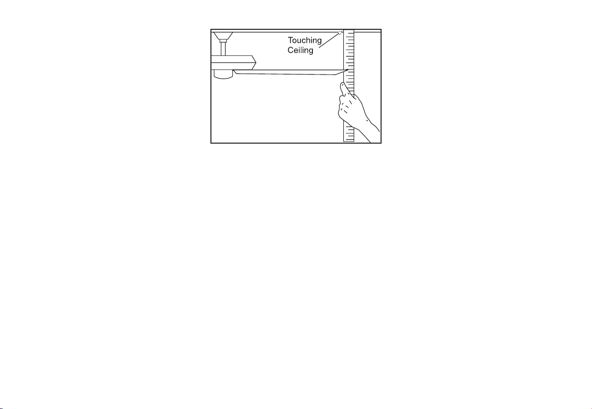
2. Most fan wobble problems are caused
when blade levels are unequal. Check
this level by selecting a point on the ceil-
ing above the tip of one of the blades.
Measure from a point on the center
of each blade to the point on the ceil-
ing. Measure this distance as shown in
Figure 15. Rotate the fan until the next
blade is positioned for measurement.
Repeat for each blade. Measurement
deviations should be within 1/8”. Run
the fan for 10 minutes.
3. Use the enclosed Blade Balancing Kit if
the blade wobble is still noticeable.
Figure 15

10. Operating Your Fan
Turn on the power and check the
operation of the fan. The pull chain
controls the fan speed as follows: 1
pull - High, 2 pulls - Medium, 3 pulls -
Low and 4 pulls - Off.
Speed settings for warm or cool
weather depend on factors such as
room size, ceiling height, number of
fans, and so on.
The reversing switch installed in the
switch cup (refer to Figure 14 on page
8) controls the direction forward (switch
down) or reverse (switch up).
Figure 16
Figure 17
WAIT FOR THE FAN TO STOP BEFORE
REVERSING THE DIRECTION OF BLADE
ROTATION.
Warm weather - (Forward) A down-
ward air ow creates a cooling effect
as shown in Figure 16. This allows you
to set your air conditioner on a higher
setting without affecting your comfort.
Cool weather - (Reverse) An upward
air ow moves warm air off the ceiling
are as shown in Figure 17. This allows
you to set your heating unit on a lower
setting without affecting your comfort.
TO REDUCE THE RISK OF PERSONAL INJURY,
DO NOT BEND THE BLADE HOLDERS WHILE
INSTALLING, BALANCING THE BLADES, OR
CLEANING THE FAN. DO NOT INSERT FOREIGN
OBJECTS BETWEEN ROTATING BLADES.

11.
Care of Your Fan
Here are some suggestions to help you
maintain your fan.
1. Because of the fan’s natural movement,
some connections may become loose.
Check the support connections,
brackets, and blade attachments
twice a year. Make sure they are
secure. (It is not necessary to remove
fan from ceiling.)
2. Clean your fan periodically to help
maintain its new appearance over the
years. Do not use water when cleaning,
this could damage the motor or the
wood or possibly cause an electrical
shock. Use only a soft brush or lint-
free cloth to avoid scratching the nish.
The plating is sealed with a lacquer to
minimize discoloration or tarnishing.
Warning - Make sure the power is off
before cleaning your fan.
3. You can apply a light coat of furniture
polish to the wood for additional
protection and enhanced beauty. Cover
small scratches with a light application
of shoe polish.
4. There is no need to oil your fan.
The motor has permanently lubricated
sealed ball bearings.
MAKE SURE THE POWER IS OFF AT THE ELECTRICAL PANEL BOX BE-
FORE YOU ATTEMPT TO MAKE ANY REPAIRS. REFER TO THE SECTION,
“MAKING ELECTRICAL CONNECTIONS.”
Fan will not start
Fan sounds noisy
Troubleshooting
Problem Solution
1. Check main and branch circuit fuses or breakers
2. CAUTION: Make sure main power is off. Check line wire con-
nections to the fan and switch wire connections in the switch
housing.
1. Make sure all motor housing screws are snug.
2. Make sure the screws that attach the fan blade bracket to the
motor hub are tight.
3. Make sure wire nut connections are not rattling against each
other or the interior wall of the switch housing.
CAUTION: Make sure power is off.
4. Allow a 24-hour “breaking in” period. Most noises associated with
a new fan disappear during this time.
5. If using the Ceiling Fan light kit, make sure the tensioners or
screws securing the glassware are tight. Check that the light bulb
is also secure.
6. Make sure the canopy is a short distance from the ceiling.
It should not touch the ceiling.
7. Make sure your outlet box is secure and rubber isolator pads
were used between the mounting bracket and outlet box.
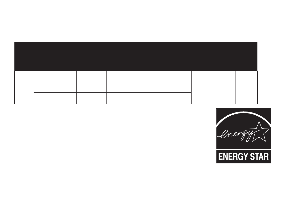
12. Specications
These are approximate measures. They do not include Amps and Wattage used by the light kit.
FAN
SIZE SPEED VOLTS AIRFLOW
(CFM)*
FAN POWER
CONSUMPTION
(WITHOUT LIGHTS)
WATTS
AIRFLOW
EFFICIENCY
(Higher is Better
CFM/watt
NET
WEIGHT
GROSS
WEIGHT
CUBE
FEET
52”
Low 120 1520.8 9.5 160.08
15.0
LBS
17.6
LBS 1.28
Med 120 3336.9 26.3 126.88
High 120 5707.1 66.4 85.95

30-Year Limited Warranty
30-Year Limited Warranty on Motor
The manufacturer warrants the fan motor to be free from defects in workmanship and ma-
terial present at time of shipment from the factory for 30 years after the date of purchase
by the original purchaser. The manufacturer also warrants that all other fan parts, exclud-
ing any glass or acrylic blades, to be free from defects in workmanship and material at the
time of shipment from the factory for a period of two years after the date of purchase by
the original purchaser. We agree to correct such defects without charge or at our option
replace with a comparable or superior model if the product is returned to the manufacturer.
To obtain warranty service, you must present a copy of the receipt as proof of purchase.
All costs of removing and reinstalling the product are your responsibility. Damage to any
part such as by accident or misuse or improper installation or by afxing any accessories,
is not covered by this warranty. Because of varying climatic conditions, this warranty does
not cover any changes in plated nishes, including rusting, pitting, corroding, tarnishing or
peeling. Brass nishes of this type give their longest useful life when protected from varying
weather conditions. A certain amount of “wobble” is normal and should not be considered
a defect. Servicing performed by unauthorized persons shall render the warranty invalid.
There is no other express warranty. The manufacturer hereby disclaims any and all war-
ranties, including but not limited to, those of merchantability and tness for a particular
purpose to the extent permitted by law. The duration of any implied warranty which can-
not be disclaimed is limited to the time period as specied in the express warranty. Some
states do not allow limitation on how long an implied warranty lasts, so the above limitation
may not apply to you. The manufacturer shall not be liable for incidental, consequential, or
special damages arising out of or in connection with product use or performance except as
may otherwise be accorded by law. Some states do not allow the exclusion of incidental
or consequential damages, so the above exclusion or limitation may not apply to you. This
warranty gives specic legal rights, and you may also have other rights which vary from
state to state. This warranty supersedes all prior warranties. Shipping costs for any return
of product as part of a claim on the warranty must be paid by the customer.
IMPORTANT NOTE:
To ensure warranty service, if ever
necessary, please register your fan at:
gpwarranty.com
You must present a copy of the original
purchase receipt to obtain warranty service.
G.P. WARRANTY SERVICE CENTER, INC.
WARRANTY SECTION
1951 N.W. 22nd STREET
FORT LAUDERDALE, FLORIDA 33311
Warranty Information 13.

Energy Select de 52” Ventilador de techo
¿PREGUNTAS, PROBLEMAS O PIEZAS FALTANTES?
Por favor, no devuelva al vendedor minorista: Llame a 1-800-749-3267 para cubrir las partes
faltantes o cuestiones relacionadas con la instalación.
Por favor usa como referencia el Nº de SKU (355-5952 blanco)
o UPC (082392 636012 blanco).
Normas de seguridad.........................1
Cómo desempacar el ventilador .......2
Cómo instalar el ventilador ...............3
Cómo operar el ventilador.................10
Cuidado del ventilador.......................11
Solución de problemas......................11
Especicaciones ................................12
Información de garantía.....................13
Índice
Número de Modelo UL : EF200M(C)-52
1. Para disminuir el riesgo de descarga eléctrica, asegúrate
de que la electricidad ha sido apagada en el cortacircuitos
o la caja de fusibles antes de comenzar la instalación.
2. Todo el cableado debe cumplir con el Código Nacional de
Electricidad ANSI/NFPA 70-1999 y con los códigos locales
de electricidad. La instalación eléctrica debe ser hecha por
un electricista certicado y calicado.
3. ADVERTENCIA: Para reducir el riesgo de incendio o
descarga eléctrica, no utilices este ventilador con ningún
dispositivo de control de velocidad de estado sólido.
4. PRECAUCIÓN: Para reducir el riesgo de lesiones físicas,
usa sólo los tornillos provistos con la caja eléctrica.
5. La caja eléctrica y estructura de soporte deben montarse
de forma segura y tener capacidad para sostener de
manera conable un mínimo de 35 libras. Usa solamente
cajas eléctricas aprobadas por UL marcadas como “PARA
SOPORTE DE VENTILADOR”.
6. El ventilador debe ir montado con un mínimo de 7 pies de
separación entre el borde trasero de las aspas y el piso.
7. No operar el interruptor de reversa mientras las aspas del
ventilador estén en movimiento. El ventilador debe estar
apagado y las aspas detenidas antes de invertir la dirección
del movimiento.
8. Evita colocar objetos en la trayectoria de las aspas.
9. Para evitar lesiones, o daños al ventilador y otros objetos;
ten cuidado al trabajar cerca del ventilador o al limpiarlo.
10. No usar agua o detergentes para limpiar el ventilador o las
aspas. En general a la hora de limpiar, bastará con usar un
paño seco o ligeramente humedecido.
11. Después de concluir con las conexiones eléctricas,
debes voltear los conductores empalmados hacia arriba y
empujarlos con cuidado hacia dentro de la caja eléctrica.
Los cables deben estar separados, con el cable a tierra y
el conductor a tierra del equipo hacia uno de los lados de
la caja eléctrica.
12. Los diagramas eléctricos son sólo una referencia. Los kits
de luces no empaquetados con el ventilador deben estar
aprobados por UL y marcados como apropiados para ser
usados con el modelo de ventilador a instalar. Los inter-
ruptores deberán estar clasicados por el UL como de Uso
General. Consulta las instrucciones adjuntas a los kits de
luces e interruptores para obtener información sobre el en-
samblaje adecuado.
13. Todos los tornillos colocados se deben vericar y ajustar
donde sea necesario antes de la instalación.
1. Normas de seguridad
LEE LAS INSTRUCCIONES Y GUÁRDALAS
PARA REDUCIR EL RIESGO DE INCENDIO, DESCARGA ELÉCTRICA O
LESIONES PERSONALES, MONTA EL VENTILADOR SOBRE UNA CAJA
ELÉCTRICA MARCADA COMO “APROBADA COMO SOPORTE DE
VENTILADOR” Y USA LOS TORNILLOS DE MONTAJE QUE VIENEN CON
LA MISMA. LAS CAJAS ELÉCTRICAS UTILIZADAS COMÚNMENTE PARA
EL SOPORTE DE ARTÍCULOS DE ILUMINACIÓN PUEDEN NO SERVIR
COMO SOPORTE DE VENTILADOR, Y TAL VEZ DEBAN REEMPLAZARSE.
EN CASO DE DUDA, CONSULTA A UN ELECTRICISTA CALIFICADO.
PARA REDUCIR EL RIESGO DE LESIONES PERSONALES, NO DOBLAR
LOS BRAZOS DE LAS ASPAS (TAMBIÉN LLAMADOS “REBORDES”)
DURANTE O DESPUÉS DE LA INSTALACIÓN. EVITA COLOCAR OBJETOS
EN LA TRAYECTORIA DE LAS ASPAS.
a. Herrajes de montaje y electricidad
(3 conectores plásticos de cable, 1 pasador
de soporte, 1 pasador de cierre)
b. Herrajes para montaje
“Cerca del Techo”
(1 junta de goma)
c. Varias piezas
(Kit de compensación de aspas,
1 cadena del ventilador para halar)
d. Herrajes adicionales para montaje de
aspas (1 tornillo y arandela de seguridad)
e. Herrajes de montaje de aspas
(15 tornillos)
5. Aspas (5)
6. Soportes del aspa (5)
1. Placa de montaje deslizante
(dentro de la cubierta)
2. Cubierta
3. Ensamblado de tubo bajante y bola
4. Ensamblado del motor del ventilador
Cómo desempacar el ventilador 2.
IMPORTANTE: ESTE PRODUCTO Y/O SUS COMPONENTES ESTÁN
PROTEGIDOS POR UNA O MÁS DE LAS SIGUIENTES PATENTES DE EE.UU.:
5,947,436; 5,988,580; 5,971,573; 6,010,306; 6,039,541; 6,046,416 y OTRAS
PATENTES PENDIENTES.
Desempaca tu ventilador y revisa el contenido. Deberá tener las siguientes piezas:

3. Cómo instalar el ventilador
Herramientas
necesarias
Destornillador Phillips, destornillador plano,
llave ajustable, escalera de tijera y
cortacables.
Opciones de
montaje
Si no hay una caja eléctrica existente,
entonces lee las siguientes instrucciones.
Desconecta la energía retirando los
fusibles o apagando los cortacircuitos.
Asegura la caja eléctrica directamente a la
estructura del edicio. Usa sujetadores y
materiales de construcción apropiados. La
caja eléctrica y su soporte deben sostener
completamente el peso en movimiento
del ventilador (al menos 35 libras).
No uses cajas eléctricas de plástico.
Las guras 1, 2 y 3 son ejemplos de
diferentes formas de montar la caja
eléctrica.
Caja eléctrica
Caja eléctrica
Soporte fuerte
Caja
eléctrica
empotrada
Placa de
montaje en
el techo
Nota: Tal vez necesites un tubo bajante
más largo para mantener la altura
mínima adecuada de las aspas al instalar
el ventilador en un techo inclinado. El
ángulo máximo permitido es de 30º.
Si la cubierta toca el tubo bajante,
retira la cubierta inferior decorativa
y gira la cubierta 180º antes de
jar la cubierta a la placa de montaje.
Caja eléctrica
Para colgar tu ventilador donde haya
una lámpara pero ninguna viga de techo,
tal vez necesites una barra colgante de
instalación como se muestra en la Figura 4.
Figura 1
Figura 2
Figura 4
Figura 3
PARA REDUCIR EL RIESGO DE INCENDIO,
DESCARGA ELÉCTRICA O LESIONES
PERSONALES, MONTA EL VENTILADOR
SÓLO SOBRE UNA CAJA ELÉCTRICA
MARCADA COMO “APROBADA COMO
SOPORTE DE VENTILADOR” Y USA LOS
TORNILLOS DE MONTAJE QUE VIENEN
CON LA MISMA. LAS CAJAS ELÉCTRICAS
UTILIZADASCOMÚNMENTE PARAELSOPORTE
DE ARTÍCULOS DE ILUMINACIÓN PUEDEN NO
SERVIR COMO SOPORTE DE VENTILADOR, Y
TAL VEZ DEBAN REEMPLAZARSE. EN CASO
DE DUDA, CONSULTA A UN ELECTRICISTA
CALIFICADO.

no apretarlo contra el cableado dentro
del tubo bajante. Inserta el pasador tipo
horquilla en el oricio cercano al extre-
mo del perno y dóblalo para garantizar
la seguridad, tal como se muestra en el
círculo de la Figura 6.
5. Vuelve a ajustar los dos tornillos del col-
larín en la parte superior de la carcasa
del motor (Figura 6).
6. Sigue con la sección “Cómo instalar el
ventilador”.
Montaje de techo
estándar
1. Retira la placa de montaje de la cubi-
erta aojando los cuatro tornillos de la
parte superior de la misma. Quita los
dos tornillos sin ranura y aoja los tornil-
los ranurados. Esto te permitirá retirar la
placa de montaje (Figura 5).
2. Inserta los cables que salen por la
parte superior del motor del ventilador
a través de la cubierta y luego a través
del ensamblado del tubo bajante y la
bola (Figura 6).
3. Aoja, sin quitarlos, los tornillos en el col-
larín ubicado en la parte superior de la
carcasa de motor.
4. Alinea los oricios en la parte inferior del
tubo bajante con los oricios en el col-
larín de la parte superior de la carcasa
de motor (Figura 7). Inserta con cuidado
el perno a través de los oricios del col-
larín y del tubo bajante. Ten cuidado de
4.
Cómo colgar el
ventilador
RECUERDA desconectar la corriente.
Sigue estos pasos para colgar
correctamente tu ventilador.
NOTA: Este ventilador de techo viene con
dos tipos de ensamblados de soporte; la
instalación de techo estándar con tubo
bajante y bola, y casquillo de montaje; y
el montaje “cerca del techo”. El montaje
“cerca del techo” se recomienda en
habitaciones con techos de menos
de 8 pies de altura o en áreas donde
sedeseeespacioadicionaldesdeelpisohasta
las aspas de ventilador. Cuando uses una
instalación con un tubo bajante
estándar, la distancia desde el techo
a la parte inferior de las aspas será de
11 pulgadas aproximadamente.
La instalación “cerca del techo”
reduce la distancia desde el techo
a la parte inferior de las aspas a
8 pulgadas aproximadamente.
Una vez elegido el tipo de instalación,
sigue con las siguientes instrucciones.
Cuando sea necesario, cada sección de
las instrucciones indicará los diferentes
procedimientos a seguir para los dos tipos
de instalación.
Aflojar pero no retirar Quitar
Figura 5
Figura 6
Cables del motor
Apretar el tornillo
firmemente
Ensamblado
de tubo
bajante/bola
Collarín
del motor
Posición
de cierre
del pasador
Cubierta
Perno
Pasador tipo
horquilla
SI NO INSTALAS CORRECTAMENTE EL
PASADOR TIPO HORQUILLA SEGÚN LO
INDICADO EN EL PASO 4 Y APRIETAS
FIRMEMENTE LOS TORNILLOS
COMO SE DESCRIBE EN EL PASO 5,
SE PUEDE AFLOJAR Y POSIBLEMENTE SE
CAIGA EL VENTILADOR.
Table of contents
Languages:
Other Energy Star Fan manuals


Popular Fan manuals by other brands

Team Kalorik
Team Kalorik TKG VT 1043 RD manual

Casablanca
Casablanca Capistrano 54029 Owner's guide and installation manual

Zephir
Zephir ZFS8120 instruction manual

Visual Comfort & Co.
Visual Comfort & Co. Maverick 3MAVR52 Series manual

Mitsubishi Electric
Mitsubishi Electric Lossnay LGH-15RX3-E Technical manual

SIGURO
SIGURO SGR-FN-S470W user manual


