ENERGY SUPPORT CORPORATION ISS-101 User manual

Manual No.3011E R5
INSTRUCTION MANUAL
FOR
DUST DENSITOMETER
MODEL ISS-101
KV-610014-J


1
1. General description
1.1 Introduction
This Dust densitometer model ISS-101 is a relative dust concentration
meter, which utilizes the light scattering method and can be used to
continuously monitor the dust concentration for an extended period of
time. The analyzer is directly connected to the flume and has a simple
sampling piping system, ensuring easy maintenance.
By supplying the clean air to the optical system, lowering of the sensitivity due to
contamination of the optical system is prevented.
Therefore, the analyzer can measure from the high concentration to low concentration
without effects of load fluctuations and does not require any maintenance for an extended
period of time.
This instruction manual describes how to install, operate, and inspect the Dust
densitometer model ISS-101. Before starting installation of this analyzer, thoroughly read
this instruction manual to fully understand its contents and operate the analyzer in correct
manner.

2
1.2 Guarantee of product
The guarantee period of this product is stated in the final document. If the
delivery drawings are not provided, the guarantee period is determined as
one year after delivery.
(1) Conditions
The product shall be stored and installed properly until the trial-run adjustment is
started. If any defect due to faulty design, defective materials, and/or poor
workmanship is found during the guarantee period, Energy Support corp. shall repair
or replace defective item free of charge.
The proper operating conditions include the following terms.
①The operating conditions and installation conditions specified in this instruction
manual shall be satisfied.
②Excessive mechanical shock and impact shall not be applied to the sampling
probe.
③The Dust densitometer shall be calibrated and consumable parts shall be
replaced periodically.
④The confirmation and maintenance of the Dust densitometer operation status
shall be performed correctly.
⑤The suction and exhaust valves shall be closed not to suck the sample gas until
the warm-up time of the transmitter has elapsed.
⑥The optical system shall be cleaned and clogging of the probe shall be inspected
and cleaned periodically.
This guarantee does not include defects arising from the following conditions
even during the guarantee period.
・Defects arising from improper handling (improper operation not stated in this
instruction manual)
・Defects arising from repair, modification, or overhaul cleaning made by
personnel other than those authorized by Energy Support corp.
・Defects arising from fire, natural disaster, or improper maintenance (storage in
a place where high temperature and high humidity exist, or mold occurs.)
Note: Replacement of consumable and/or similar parts is not included in the
guarantee coverage.
(2) Guarantee coverage
This guarantee covers only products manufactured and delivered by Energy Support
corp. Incidental and consequential damages (damage and loss caused by controlled
and recorded results by the product delivered by Energy Support corp. and damage
and loss of the equipment, in which Energy’s product is installed) resulting from
malfunction of the product manufactured by Energy Support corp. are not included.
IMPORTANT

3
(3) Remarks
①It is difficult to remove the slug dust by purging. It is absolutely necessary to
perform the maintenance and replacement work with the probe removed.
②This instrument is a Dust densitometer that utilizes the light scattering method.
When measuring the dust actually, a difference between the indication value on
the Dust densitometer and weight concentration value of the actual dust may be
produced by influences of the color, shape, and grain size of the dust.
Therefore, the customer needs to perform the manual analysis and add the
compensation value from the following weight conversion coefficient to make the
indication value on the Dust densitometer matched with the weight concentration
value.
Weight conversion coefficient =
(Actual dust weight concentration value (mg/m3N)
(Average of indication value on the Dust densitometer
(mg/m3N))
This compensation is similar to the standard gas calibration of the gas analyzer.

4
Table of contents
1. General description-------------------------------------------------------------------------------------------------------- 1
1.1 Introduction ------------------------------------------------------------------------------------------------------------- 1
1.2 Guarantee of product ------------------------------------------------------------------------------------------------ 2
1.3 Table of contents------------------------------------------------------------------------------------------------------ 4
1.4 Safety precautions---------------------------------------------------------------------------------------------------- 6
1.5 Cautions for operation ----------------------------------------------------------------------------------------------- 7
1.6 Overview of Dust densitometer------------------------------------------------------------------------------------ 8
1.7 Part names and functions------------------------------------------------------------------------------------------- 9
2. After unpacking------------------------------------------------------------------------------------------------------------11
2.1 Checking of accessories -------------------------------------------------------------------------------------------11
2.2 Temporary storage of product-------------------------------------------------------------------------------------13
3. Installation ------------------------------------------------------------------------------------------------------------------14
3.1 Installation conditions-----------------------------------------------------------------------------------------------14
3.2 Installation--------------------------------------------------------------------------------------------------------------16
3.3 Piping and wiring-----------------------------------------------------------------------------------------------------19
3.4 Inspection after installation ----------------------------------------------------------------------------------------22
4. Operation -------------------------------------------------------------------------------------------------------------------23
4.1 Preparations for operation-----------------------------------------------------------------------------------------23
4.2 Key operation ---------------------------------------------------------------------------------------------------------26
4.3 List of functions-------------------------------------------------------------------------------------------------------31
4.4.1 List of system data (user data)------------------------------------------------------------------------------33
4.4.2 List of system data (manufacturer data)------------------------------------------------------------------35
4.5 Starting operation----------------------------------------------------------------------------------------------------37
4.6 Stopping operation---------------------------------------------------------------------------------------------------38
4.7 Operation while analyzer is running-----------------------------------------------------------------------------39
4.7.1 Measuring range change operation------------------------------------------------------------------------39
4.7.2 Calibration operation-------------------------------------------------------------------------------------------40
4.7.3 Purge and bypass operation---------------------------------------------------------------------------------47
4.7.4 O2 conversion/weight conversion operation-------------------------------------------------------------49
4.7.5 Output signal calculation/hold/output adjustment ------------------------------------------------------51

5
5. Maintenance ---------------------------------------------------------------------------------------------------------------54
5.1Cautions for maintenance ----------------------------------------------------------------------------------------54
5.2 Maintenance and inspection items ------------------------------------------------------------------------------55
5.3 Maintenance and inspection --------------------------------------------------------------------------------------56
5.4 Error display-----------------------------------------------------------------------------------------------------------66
5.5 Troubleshooting ------------------------------------------------------------------------------------------------------68
5.6 Replacement parts---------------------------------------------------------------------------------------------------75
5.7 Replacement of parts -----------------------------------------------------------------------------------------------77
5.8About transmitter-----------------------------------------------------------------------------------------------------78
6. References -----------------------------------------------------------------------------------------------------------------79
6.1 Construction of unit--------------------------------------------------------------------------------------------------79
6.2 Outside view and dimensional drawing-------------------------------------------------------------------------80
6.3 Standard specifications---------------------------------------------------------------------------------------------83
6
1.4 Safety precautions
WARNING
1. Before starting the wiring work to the terminal block, always
shut-down the power. Failure to do so may cause an electrical
shock. Additionally, before starting the maintenance work of electrical
parts, always shut-down the power.
2. To prevent an electrical shock accident, connect the grounding cable to the
grounding terminal firmly.
CAUTION
1. To prevent dew condensation, the transmitter main body becomes hot.
Before starting the cleaning and maintenance work of the piping in the optical
system, trap, and ejector, always wear heat-resistant gloves.
2. Before attaching and detaching the cap to/from the span port, always wear
heat-resistant gloves since the span port is hot.
3. If the suction and exhaust valves are not closed fully when starting the
maintenance work while the furnace is being operated, the sample gas may spout
out.To prevent such troubles, always close the suction and exhaust valves fully.
4. Before installing or removing the Dust densitometer, make sure that the furnace
operation is stopped completely.
If it is strongly required to install or remove the Dust densitometer while the furnace
is being operated, pay special attention to the following cautions.
(1) Since the part close to the mounting seat is hot, always wear heat-resistant
gloves.
(2) If the positive pressure exists inside the furnace, the sample gas may spout
out
from the opening. Never get access to the opening.
(3) Additionally, the dust and soot in the sample gas may also spout out.Always
wear dust-proof glasses to prevent dust and soot from entering your eyes.
IMPORTANT

7
1.5 Cautions for operation
CAUTION
The following cautions must be strictly observed to prevent corrosion
and clogging of dust caused by dew condensation. Always operate
the Dust densitometer correctly while carefully referring to the following
operations.
1. Close the suction and exhaust valves if the HEAT lamp on the controller does not
flash or if the warm-up operation is not performed for 60 min.
2. If the power to the transmitter is shut-down due to power failure, immediately close
the suction and exhaust valves.
3. Perform the heat retention (heat insulation) work on the sample gas flowing pipes
between the furnace wall (guide pipe) and transmitter.
4. The dust concentration inside the furnace becomes high during a period of
approximately 2 hrs.After stopping or starting the furnace operation, causing the
optical system of the Dust densitometer to be contaminated. Therefore, close the
suction and exhaust valves for approximately 2 hrs. after stopping or starting the
furnace operation in order to prevent the dust from entering the analyzer.
5. Open and close the suction and exhaust valves periodically (once a month). If the
valves are not operated for an extended period of time, dust may stick to the valves,
causing the valves not to be opened or closed.
IMPORTANT
8
1.6 Overview of Dust densitometer
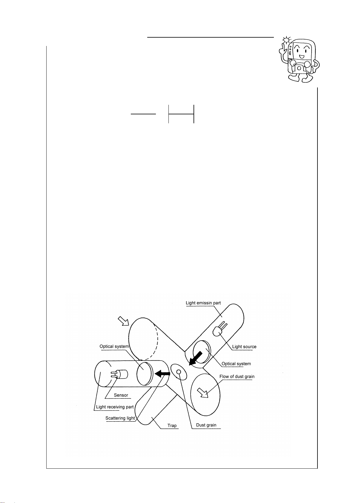
[Measuring principle]
This Energy’s Dust densitometer is a light scattering type Dust
densitometer that utilizes the correlation between the dust weight
concentration and scattering intensity.
The light scattering intensity (I
) is expressed by the following formula.
I=
2
6
m2–1
2
(1 + cos2)
822
m2+ 1
: Scattering angle,
: Wavelength,
: Grain diameter parameter (2
a/
), a: Radius of
grain, R: Distance from grain, m: Index of refraction of light in grain/Index of refraction of
light in medium
When the physical property of the grain (shape, size, composition, color, etc.) is almost
constant, the scattering intensity is parallel to the dust weight concentration.
An infrared ray LED lamp with an emission light waveform of 875 nm is used as light
source.
When this light is intermittently emitted to the dust passing through the detection area of
the detector, the scattering light occurs at any angle to the dust.
A light receiving sensor is located at 70
forward to the light axis between the light source
and trap. This sensor receives the infrared ray coming from the light source and
converts it into the electrical signals.
These electrical signals are processed to measure the relative dust concentration at
real-time.
Using the standard grain, scales are put on this Dust densitometer. When measuring the
exhaust gas, it is possible to perform the continuous measurement by calculating the
weight conversion coefficient based on the measurement in conformity with JIS Z 8808.
REFERENCE
9
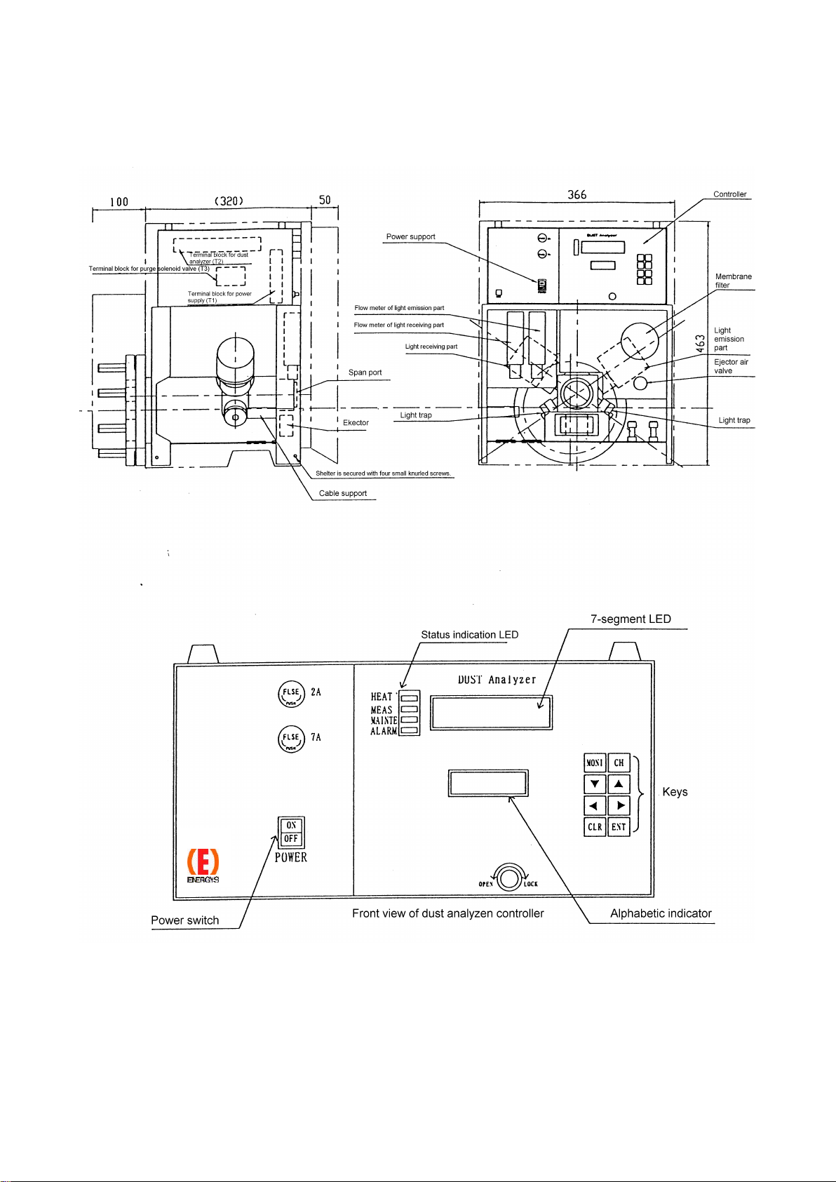
1.7 Part names and functions
1) Outside view of Dust densitometer

10
2) Part names and functions of Dust densitometer
No.
Name
Function
1
Controller
Processes the signals inside the Dust densitometer.
2
Power switch
ON/OFF switch for the power to the Dust densitometer
3
HEAT LED
Pilot lamp of the heater for the Dust densitometer.
Lit during temperature rise and flashes during control.
4
MEAS LED
Lit during measurement.
5
MAINTE LED
Lit during measurement.
6
ALARM LED
Lights up if a fault occurs.
7
7-segment LED
Indicates the dust concentration and error No.
8
Alphabetic indicator
Indicates the measuring range and status, such as CAL or
PURGE.
9
Fuse 2A
Fuse for the electronics circuit.
Fuse 7A
Fuse for the heater of the Dust densitometer
10
Flow meter of light emission
part
Flow meter for clean air of the light emission part
11
Flow meter of light receiving
part
Flow meter for clean air of the light receiving part
12
Ejector air valve
Flow regulation valve for driving of the ejector
13
Span port
Span rod is inserted into this port for span calibration.
Cleaning port for cleaning of the suction side
14
Ejector
Ejector nozzle for suction of the sample gas
When cleaning the exhaust side, remove this ejector and clean
it.
15
Filter membrane
Filter for clean air
16
Light emission part
Infrared LED light source built-in unit
17
Light receiving part
Light sensor and amplifier built-in unit used to detect the
scattering light.
18
Light trap
Absorbs the stray light.
19
Suction/exhaust nozzle
Nozzle used to suck/exhaust the sample gas.
20
Suction/exhaust valve
Valve used to shut-down the sample gas during calibration.
21
Terminal block for power
supply (T1)
Terminal block for power supply to the Dust densitometer
22
Terminal block for Dust
densitometer (T2)
Terminal block for signals to the Dust densitometer
23
Terminal block for purge
solenoid valve (T3)
Terminal block for driving of the purge solenoid valve for the Dust
densitometer
11
2. After unpacking
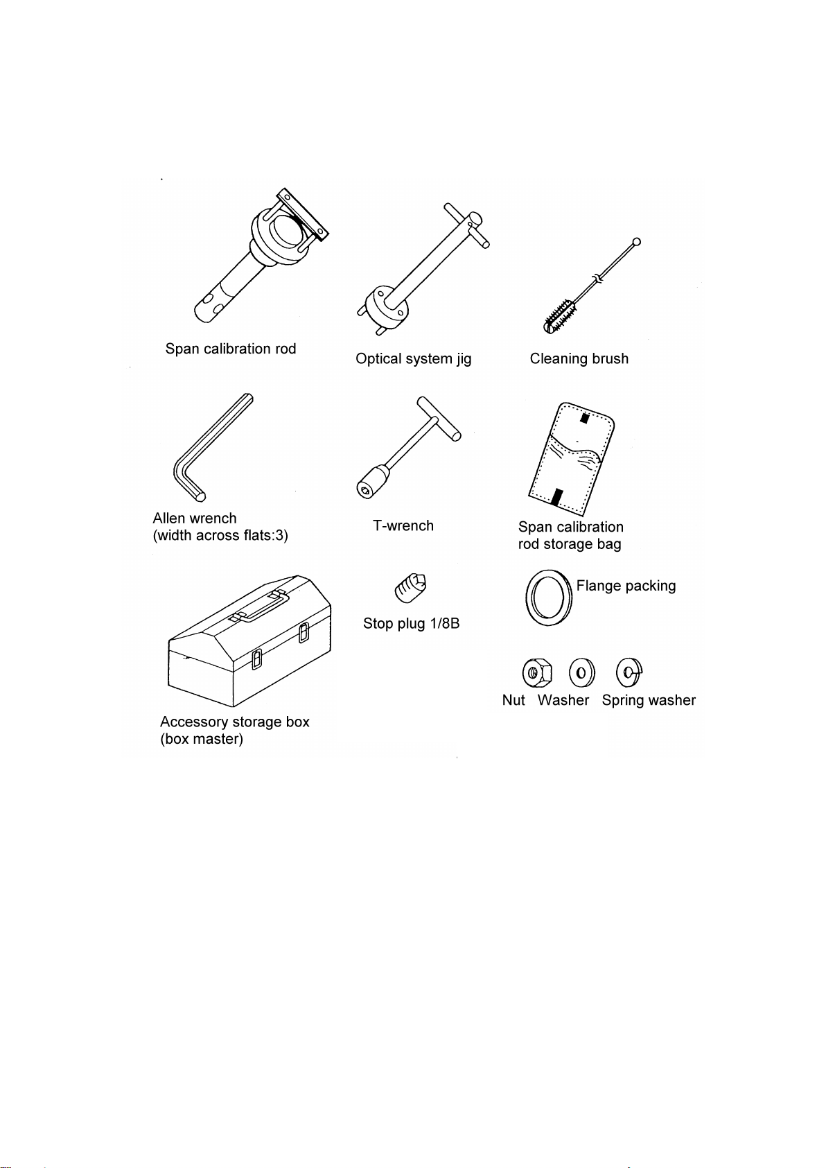
2.1 Checking of accessories

12
List of products and accessories
Name
Part No.
Q’ty
Remarks
Dust densitometer model
ISS-101
KV-610014-J
1
With case (shelter)
Suction nozzle
KV-620212-L
1
L = Specified length (mm)
Exhaust nozzle
KV-620212-L
1
L = Specified length (mm)
Span calibration rod
KV-610402-A
1
Optical system jig
KV-650105
1
Cleaning brush
KV-650106
1
T-wrench
KV-650132
1
Span calibration rod storage
bag
1
L size
Accessory storage box
1
B-54
Stop plug
PG3041/8B
1
Used to stop the air inlet of the ejector
nozzle when the ejector is not in use.
Stop plug
PG3161B
1
Supplied with the Dust densitometer
main unit
Allen wrench
1
Width across flats: 3
Nut
8
For M16
Washer
8
For M16
Spring washer
8
For M16
Flange packing
T1995K10A100RF3T
1

13
2.2 Temporary storage of product
This Dust densitometer must be stored under original packing conditions
in an indoor place (temperature: -5 –50
C, humidity: 90%RH or less) until
the installation work is started.
Do not store the Dust densitometer in an outdoor place (exposed to the rain) or a place
where high temperature or high humidity exists, or mechanical vibration exists. Doing so
may cause the Dust densitometer to malfunction.
When the Dust densitometer is installed, close the door and cure the Dust densitometer
so that rain water and dust does not enter the inside through the piping port or wiring port.
In the same manner, cure the probe and transmitter.
CAUTION

14
3. Installation
3.1 Installation conditions
This section describes how to carry out the installation, piping, and wiring
work of the Dust densitometer model ISS-101.
If the installation place is selected incorrectly or the installation work is performed
incorrectly, an unexpected trouble may occur later or the performance of the analyzer
cannot be maintained, causing damage to the units. Thoroughly read the following
description to fully understand its contents before staring the installation work.
If it is difficult to install the Dust densitometer under the conditions specified below,
contact Energy Support corp. Before installing the Dust densitometer, determine or
prepare the following items.
①Determine the gas sampling position (Dust densitometer installation position)
②Determine the storage panel (purge unit) installation place.
Cautions for installation work ( CAUTION)
1) Before installing or removing the Dust densitometer, make sure that the furnace
operation is stopped completely.
If it is strongly required to install or remove the Dust densitometer while the furnace
is being operated, pay special attention to the following cautions.
(1) Since the part close to the mounting seat is hot, always wear heat-resistant
gloves.
(2) If the positive pressure exists inside the furnace, the sample gas may spout
out from the opening. Never get access to the opening.
(3) Additionally, the dust and soot in the sample gas may also spout out. Always
wear dust-proof glasses to prevent dust and soot from entering your eyes.
2) Make sure that the suction and exhaust valves are closed fully.
If these valves are not closed fully, this may cause dust clogging or corrosion.
3) Attach the flange packing (accessory) so that it does not deviate.
4) Apply the burn prevention agent (mori-coat) to the hexagon bolts and tighten the
hexagon bolts and nuts (accessories) evenly.
IMPORTANT

15
3.1 Installation conditions
①Selection of gas sampling position
When selecting the gas sampling position, that is, Dust densitometer
installation position, always take the place satisfying the following
conditions into consideration.
1) Place where the typical dust value can be measured.
2) Place where the dust concentration does not vary rapidly.
3) Place where is close to the manual analysis seat.
4) Place where the gas temperature is 500
C or less.
5) Place where the sample gas forms an even laminar air flow.
(It is not appropriate to install the Dust densitometer at a corner where the turbulent
flow occurs easily.)
6) Place where the mechanical vibration and impact are minimized.
7) Place where the maintenance work can be carried out easily.
Keep the maintenance area satisfying the following conditions.
a. Place where is approximately 1000 mm above the center and both sides of the
mounting seat. (It is necessary to attach and detach the shelter.)
b. Place where is located 1000 mm + overall length of the nozzle after the
mounting seat.
8) Place where the outdoor temperature is –10 - 50
C.
②Selection of storage panel (purge unit) installation place
When selecting the storage panel installation place, always take the following
conditions into consideration.
1) Place where the outdoor temperature is 0 - 50
C and variation in temperature is
15
C or less during daytime.
2) Place where the corrosive gas is minimized.
3) Place where the mechanical vibration and impact are minimized.
4) Place where the Dust densitometer is not exposed to the steam or hot air.
5) Place where the Dust densitometer is not exposed to the direct sunlight.
6) Place where the electro-magnetic induction is minimized.
(Pay special attention to this caution for wiring place.)
7) Place at a distance of 50 m or less from the transmitter.
(To reduce the piping and wiring construction costs and suppress increase in
piping resistance, the above distance shall be made as short as possible.)
8) Place where maintenance space to allow opening and closing of the door of the
storage panel can be kept.
IMPORTANT

16
3.2 Installation
1) Preparations
①Wind a seal tape on the screw parts (R 3/4 male-screw) of the suction and exhaust
nozzles.
②Remove four shelter mounting screws from the Dust densitometer. Raise the shelter
to remove it. Apply the burn prevention agent (mori-coat, etc.) to eight M16 bolts
welded to the flange of the Dust densitometer.
17
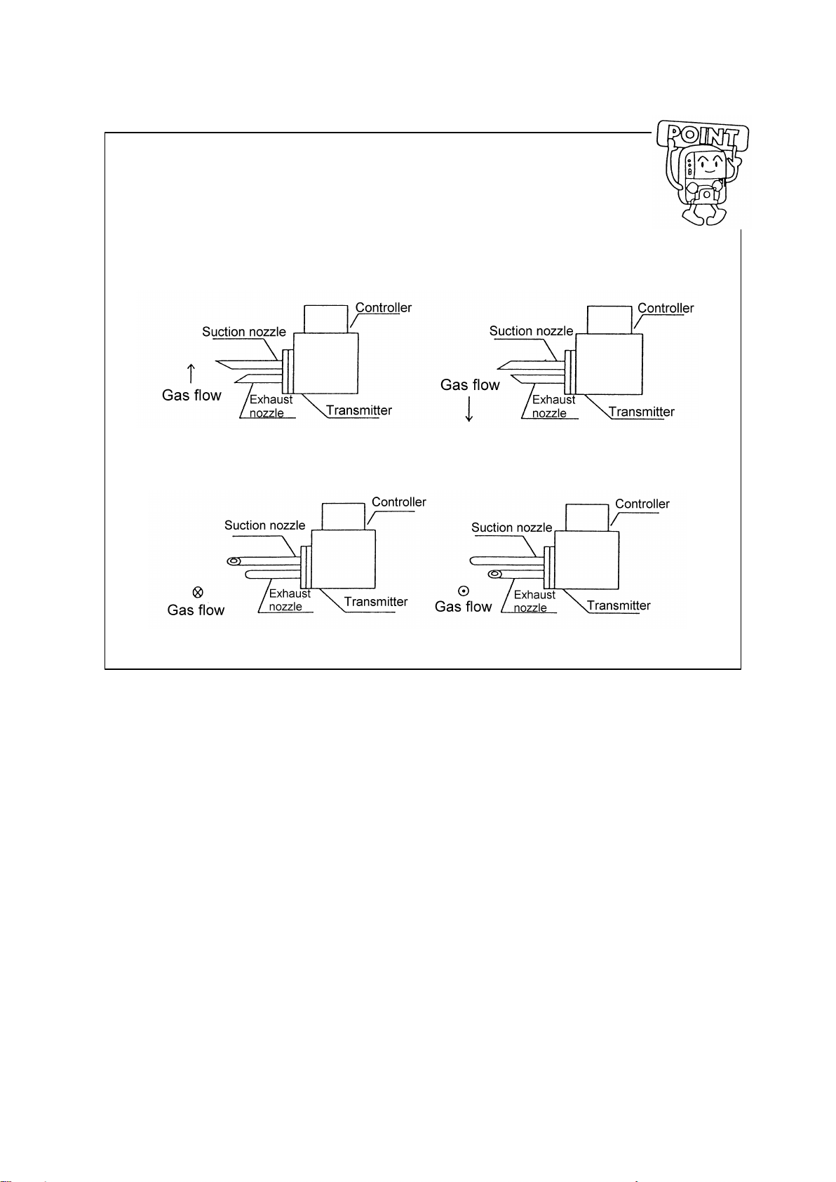
2) Procedures
①Screw the suction and exhaust nozzles into the flange.
Make the opening of the suction nozzle faced toward the gas
flow and the opening of the exhaust nozzle faced against the gas
flow as shown in the following.
a. Gas flows from the bottom to the top. b. Gas flows from the top to the bottom.
c.Gas flow fromthefrontsidetothefar side. d.Gas flow fromthefarsidetothefrontside.
To screw-in the suction and exhaust nozzles, first turn the nozzles manually, and then
retighten them with a pipe wrench.
(If the nozzles are not retightened with a pipe wrench, the nozzle may fall down
during operation.)
(If the nozzles cannot be positioned as shown in the Fig. above after the nozzles
have been screwed in, adjust the positions by increasing or decreasing the seal tape
winding amount.)

18
②Insert the M16 bolt of the Dust densitometer into the mounting seat (guide pipe),
attach the M16 washer, spring washer, and hexagon nut in that order, and then
tighten the nut.
(At this time, check that the suction and exhaust valves are closed fully.)
In the above assembly, always attach the flange packing (T1995-10K100RF3T).
Since the weight of the Dust densitometer is approximately 40 kg, always
carry out the installation work by two or more personnel.
③Carry out the heat retention work of the mounting seat (guide pipe).
Dimensions of guide pipe work (beyond delivery conditions)
(Reference)
*1 Carry out the heat retention work of the guide pipe.
CAUTION
Table of contents
Other ENERGY SUPPORT CORPORATION Measuring Instrument manuals

Popular Measuring Instrument manuals by other brands


HF Scientific
HF Scientific CLX owner's manual

Zehntner
Zehntner ZGM1130 Technical manual

ATAGO
ATAGO PAL-Easy ACID1 instruction manual

PCB Piezotronics
PCB Piezotronics HT352A21/NC Installation and operating manual

Hydrofarm
Hydrofarm Active Eye LGBQM Quantum PAR Meter instruction manual

Satimo
Satimo EME Guard user manual