6
Notes:
• Air or electric powered pumps only: Once the blade has
stopped cutting at 1000 psi [69 bar], the pressure should be
gradually increased using the pressure regulator on the pump.
Allow adequate time for the blade to cut before increasing
pressure.
• If pressure is increased too quickly, blade damage may result.
Excessive pressure may also cause the nut splitter's internal
relief valve to open, resulting in oil leakage from the oil bleed
hole located on the underside of the blade holder.
• On larger nuts, it may be helpful to periodically retract and re-
lubricate the blade. This will reduce friction and increase blade
efficiency.
11. Continue to apply hydraulic pressure until the nut is
completely severed. As the nut splits, a loud “crack” will be
heard, indicating that the nut has been severed.
12. If necessary, a second cut
may be applied, at 180° to
the first, completely severing
the nut in half. See Figure
10.
IMPORTANT: Do not cut the
nut into small pieces. Use a
maximum of two cuts and always
at 180º (opposite) to the first.
Otherwise, nut metal fragments
may be released.
13. After the cut is completed:
• Single acting models: Release the pressure to retract
the nut splitter blade.
• Double acting models: Move the control valve to the
retract position to retract the nut splitter blade.
14. Stop the pump. Check that pressure gauge indicates zero
(0) psi/bar.
15. Remove nut splitter from the nut.
16. Remove the severed nut from the stud.
6.4 If Nut Does Not Split at Full Hydraulic Pressure
If the nut splitter is at full pressure, 10,000 psi [700 bar], and
the nut does not split:
WARNING
: Fully release hydraulic pressure and
disconnect hydraulic hose(s) from nut splitter cylinder
before applying lubricant to blade or performing any
other work inside the cutting zone.
1. Ensure that the blade cutting depth setting is correct. Also,
check that the cylinder is not at full stroke.
2. If the blade cutting depth setting is correct and cylinder
is not at full stroke: Release hydraulic pressure and rotate
the cylinder clockwise one full turn. This will allow the blade
to advance 1 to 2 mm further. Then, re-apply hydraulic
pressure and try again to split the nut.
3. If step 2 did not work: Release hydraulic pressure. Re-
lubricate the blade and the groove in the nut where the
blade has penetrated. Then, re-apply pressure, ensuring
that the blade is positioned back in the same nut groove.
4. If step 3 did not work: Re-lubricate the blade and the
nut groove again. Lift and position the nut splitter above
the flange surface so that the blade will penetrate the nut
approximately ²⁄³the height of the nut, and in the same
groove. Then, re-apply pressure.
5. If step 4 did not work: Install a larger cutting head (if
available) or use a larger nut splitter model. Be certain
that the nut size is within the larger equipment's operating
range.
6.5 After Using the Nut Splitter
1. Ensure that the nut splitter cylinder is fully retracted. If it
is fully or partially advanced, reconnect the cylinder to
the pump and allow time for full retraction to occur. After
ensuring that there is no pressure present in the system,
disconnect the hydraulic hose(s) from the cylinder.
2. Using a clean cloth, wipe away any debris from the nut
splitter components. Pay particular attention to the cutting
head and blade area. Remove all traces of lubricant from
the blade.
3. Reinstall dust caps and/or plugs on all hydraulic couplers.
4. If the nut splitter is to be stored in damp conditions or will
not be used for a long period of time, coat exterior surfaces
with a water-repellent spray or similar removable protective
coating.
5. Store the nut splitter subassemblies in their storage cases.
7.0 CUTTING BLADE REPLACEMENT
The blade features three separate cutting edges. If one edge
becomes damaged or severely chipped, the blade can be
removed, rotated 120 degrees, and reinstalled to provide a
new cutting edge.
IMPORTANT: After all three edges are worn, the blade should
be replaced. Do not attempt to sharpen worn or damaged
blades.
Replace the blade as described in the following steps. See
Figure 11.
1. Be sure that nut splitter cylinder is fully retracted and that
pressure gauge indicates zero (0) psi/bar. Disconnect
hydraulic hose(s) from cylinder coupler(s).
2. Slide the blade from the holder and out through the
underside of the head. If the blade is tight, a light tap on the
top surface of the blade should free it from the ball detent
mechanism.
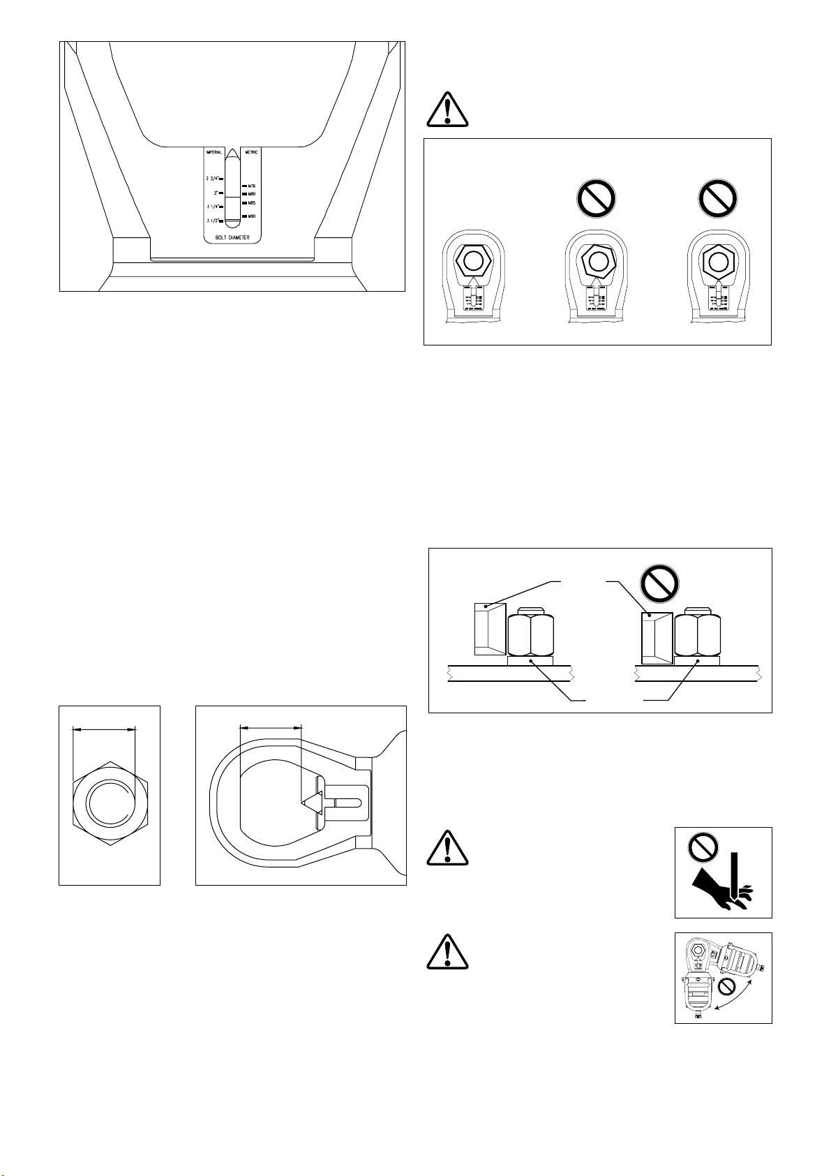
C
AUTION: Be careful when handling blades. Fractured
edges can be sharp. Wear appropriate hand protection
when removing and installing blades.
3. Determine if the old blade has any reusable edges. If a new
blade is to be installed, refer to Section 3.1 for replacement
blade part numbers. Be sure to use the proper blade for the
cutting head used on your nut splitter model.
Ball Detent
Blade
(removed)
Blade
(installed)
Figure 11, Cutting Blade Replacement
Fig. 10, Making Two Cuts