Engel R2500IS User manual
2.5kW
R2500IS -


Thank you for choosing the Engel inverter type unleaded engine generator set
All information in this publication is based on the latest product information
available at the time of printing. The contents in this manual may be different
from the actual parts due to revision and other changes.
Our company reserves the right to make changes at any time without notice
and without incurring any obligation. No part of this publication may be
reproduced without our company’s written permission.
This manual should be considered a permanent part of the generator and should
accompany the generator if it is resold.
- 1 -
Please read this Owner’s Manual carefully before operating the unit.
SAFETY WARNINGS
Personal safety and property safety of you and others are very important. .
Please read these messages which is preceded by a symbol or
carefully.
- 2 -

SAFETY WARNINGS .................
1. SAFETY INFORMATION......................................................................... 5
2. LOCATION OF IMPORTANT LABELS................................................... 9
3. DESCRIPTION......................................................................................... 10
3.1 Control panel....................................................................................... 11
4. CONTROL FUNCTION........................................................................... 12
4.1 3 in 1 switch knob.............................................................................. 12
4.2 Oil warning light (Red)....................................................................... 12
4.3 Overload indicator light (Red)........................................................... 13
4.4 AC pilot light (Green)........................................................................ 13
4.5 Engine smart control (ESC)............................................................... 14
4.6 Fuel tank cap...................................................................................... 15
4.7 Fuel tank cap air vent knob................................................................ 15
4.8 Ground (Earth) terminal..................................................................... 15
5. PREPARATION........................................................................................ 16
5.1 fuel......................................................................................................16
5.2 Engine oil........................................................................................... 17
5.3 Pre-operation check...........................................…............................. 18
6. OPERATION....................................…..................................................... 19
6.1 Starting the engine..................................…........................................ 20
6.2 Stopping the engine............................................................................ 21
6.3 Alternating Current (AC) connection................................................. 22
6.4 USB Socket............................................…........................................ 23
6.5 Application range....................................…....................................... 24
6.6 Voltage/Frequency/Time........................…....................................... 25
................................................................... 2
CONTENTS
- 3 -

7. MAINTENANCE.................................................................... . 26
7 1 Spark plug inspection......................................................................... 28
7.2 Carburetor adjustment........................................................................ 29
7.3 Engine oil replacement....................................................................... 29
7.4 Air filter.............................................................................................. 30
7.5 Muffler screen and spark Arrester...................................................... 31
7.6 Fuel tank filter.................................................................................... 32
7.7 Fuel filter............................................................................................ 32
8. STORAGE................................................................................................ 33
8.1 Drain the fuel..................................................................................... 33
8.2 Engine................................................................................................ 34
9. TROUBLESHOOTING............................................................................ 35
9.1 Engine won’t start.............................................................................. 35
9.2 Generator won’t produce power......................................................... 35
10. SPECIFICATIONS................................................................................. 36
11. WIRING DIAGRAM............................................................................. 37
.................
.
- 4 -

Read and understand this owner’s manual before operating your generator. It
will help you avoid accidents if you get familiar with your generator’s safe
operation procedures.
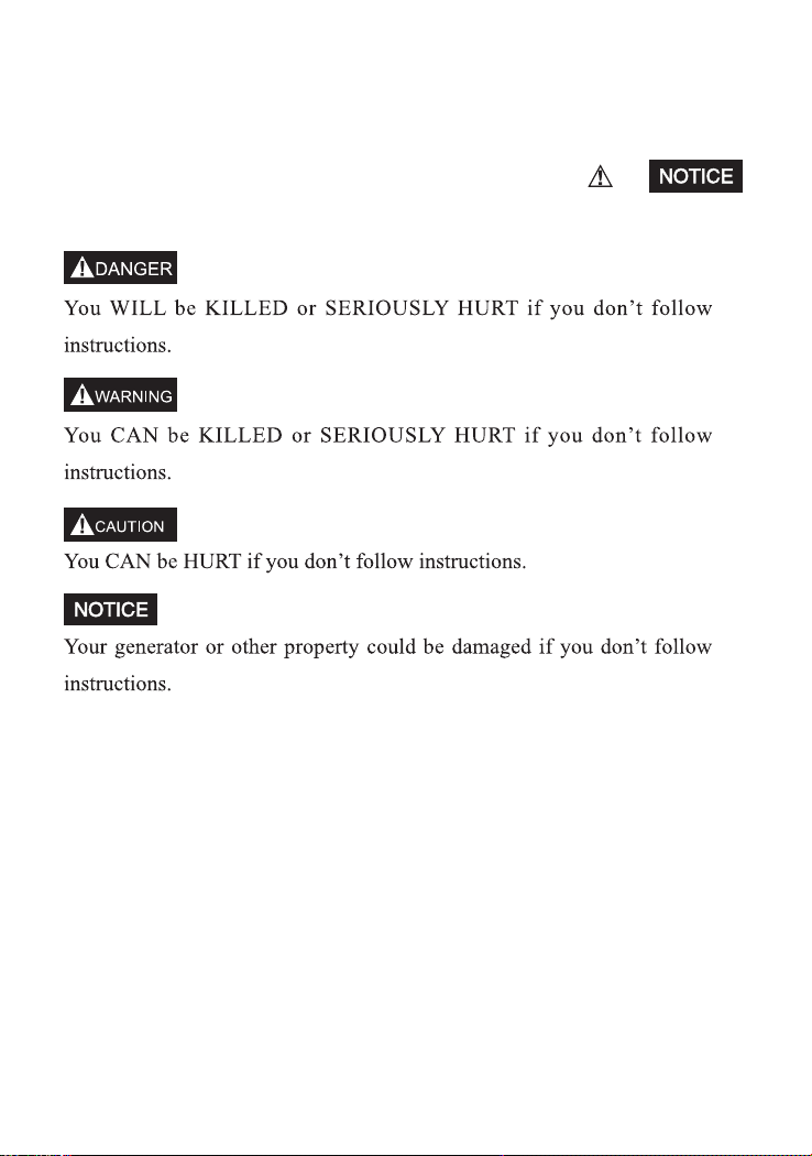
1. SAFETY INFORMATION
Never use it indoors Never use it in a wet conditions
Never directly connect it to a home power system
- 5 -
Keep it at least 1m away from
inflammables
Never smoke when fueling
Don’t spill when fueling Stop the engine before fueling
- 6 -

If the generator is to be connected to a home power supply as a standby,
connection shall be performed by a professional electrician or by another
person with proficient electrical skill.
When the loads are connected to the generator, please carefully check whether
electrical connections are safe and reliable. Any improper connection may
cause damage to the generator, or cause a fire.
Connections to a Home Power Supply
- 7 -
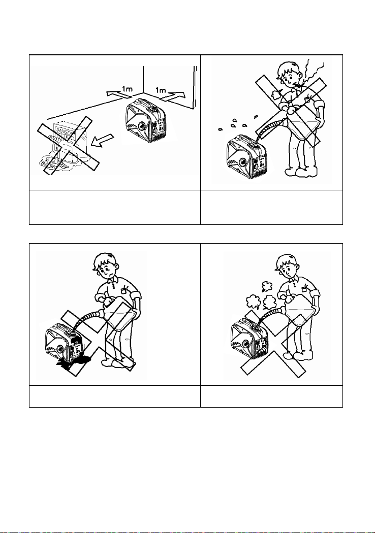
Generator Ground Circuit
In order to prevent electric shock due to shoddy electrical appliances or wrong
use of electricity, the generator must be grounded with a good-quality insulated
conductor.
Ground terminal
- 8 -
Make sure no chips, mud and water come inside of the unit from openings of
control panel, louver and inverter. Otherwise, the unit may be damaged.
Do not use, transport or store unit with the other objects. Otherwise, fuel leakage
may cause unit damage or your other property safety issue when happened.

Please read the following labels carefully before operation this machine.
TIP : Maintain or replace safety and instruction labels, as necessary.
2. LOCATION OF IMPORTANT LABELS
- 9 -
5
4
5
4
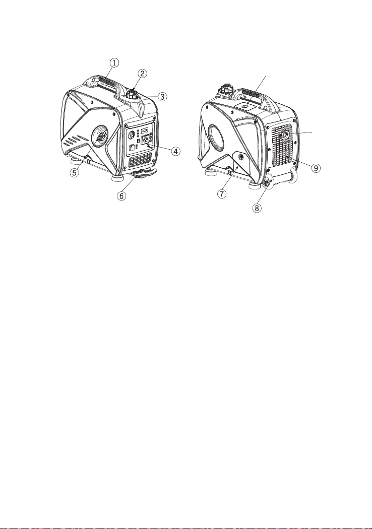
3. DESCRIPTION
①Carrying handle
②Fuel tank cap air vent knob
③Fuel tank cap
④Control panel
⑤Recoil starter
⑥
Oil filler cap
Handle
Inverter wheel
⑦
Louver
⑧
Muffler
⑨
⑩
⑩
⑪
⑪Spark plug maintenance cover
- 10 -

3.1 Control panel
①
Oil warning light
AC Reset
Parallel function
V.F.T Meter (Voltage/Frequency/Time)
②Overload indicator light
③
AC pilot light
④
ESC(Engine Smart Control)
⑤
3 in 1 switch knob (including start/stop switch, fuel valve
and choke)
⑥
AC receptacle
⑦
⑧
Ground (earth) terminal
⑨
AC Protector⑩
USB
- 11 -
⑩

4. CONTROL FUNCTION
4.1 3 in 1 switch knob
①Engine switch \fuel valve “OFF”;
Ignition circuit is switched off. Fuel is switched off.
The engine will not run.
②Engine switch \fuel valve \ choke “ON”
Ignition circuit is switched on. Fuel is switched on. Choke is switched on.
The engine can be running.
③Engine switch \fuel valve \ choke “CHOKE” ;
Ignition circuit is switched on. Fuel is switched on. Choke is switched off.
The engine can be started.
TIP: The choke “ ” is not required to start a warm engine.
;
4.2 Oil warning light (Red)
When the oil level falls below the lower level, the oil warning light comes
on and then the engine stops automatically. Unless you refill with oil, the
engine will not start again.
①
Tip: If the engine stalls or does not start, turn the engine switch to “ON” and
then pull the recoil starter.
If the oil warning light flickers for a few seconds, the engine oil is insufficient.
Add oil and restart.
- 12 -
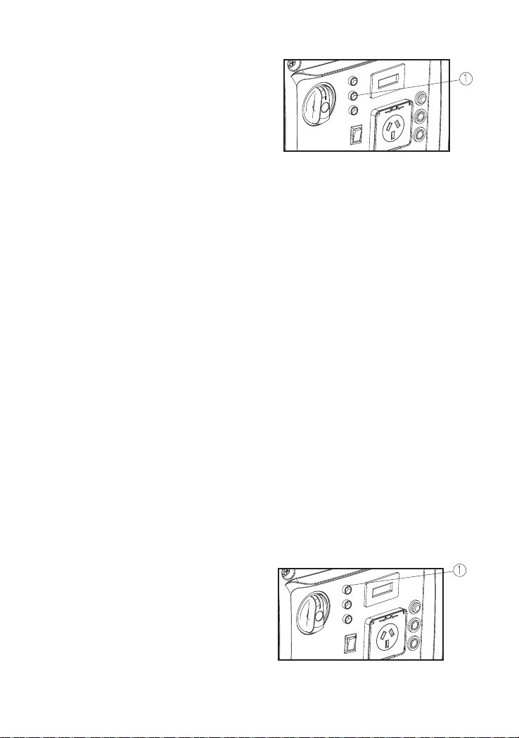
The overload indicator light ①comes on when an overload of a connected
electrical device is detected, the inverter control unit overheats, or the AC
output voltage rises. Then, the AC protector will trip, stopping power generation
in order to protect the generator and any connected electric devices. The AC
pilot light (Green) will go off and the overload indicator light (Red) will stay
on, but the engine will not stop running.
When the overload indicator light comes on and power generation stops,
proceed as follows:
1. Turn off any connected electric devices and stop the engine.
2. Reduce the total wattage of connected electric devices within the rated
output.
3. Check for blockages in the cooling air inlet and around the control unit.
If any blockages are found, remove.
4. After checking, restart the engine.
4.3 Overload indicator light (Red)
Tip: The overload indicator light may come on for a few seconds at first when
using electric devices that require a large starting current, such as a compressor
or a submergible pump. However, this is not a malfunction.
4.4 AC pilot light (Green)
The AC pilot light ① comes on when the engine starts and produces power.
- 13 -

4.5 Engine smart control (ESC)
①“ON”
When the ESC switch is turned to “ON”, the economy control unit
controls the engine speed according to the connected load. The results
are better fuel consumption and less noise.
②“OFF”
When the ESC switch is turned to“OFF”, the engine runs at the rated
r/min(4400r/min) regard-less of whether is a load connected or not.
Tip:
The ESC must be turned to“OFF”when using electric devices that require
a large starting current, such as a compressor or a submergible pump.
- 14 -

- 15 -
4.6 Fuel tank cap
Remove the fuel tank cap by turning it
counterclockwise.
4.7 Fuel tank cap air vent knob
The fuel tank cap ② is provided with an air vent knob
to ① stop fuel flow. The air vent knob must be turned
to “ON”. This will allow fuel to flow to the carburetor and the engine to run.
when the engine is not in use, turn the air vent knob to “OFF” to stop fuel
flow.
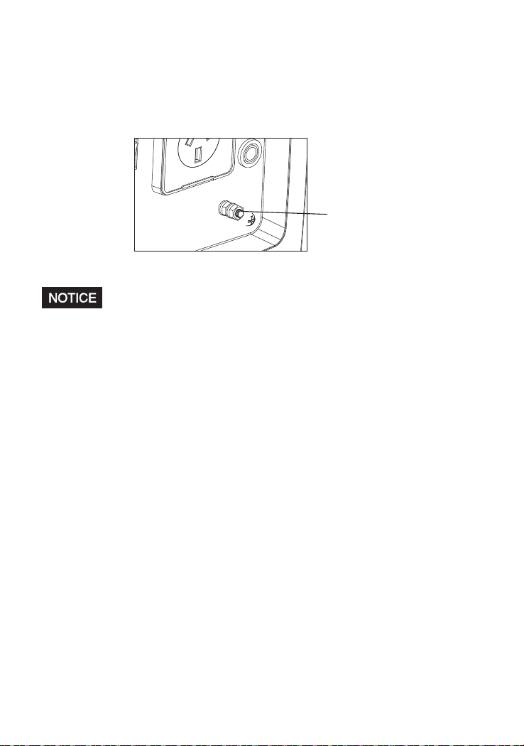
4.8 Ground (Earth) terminal
Ground (Earth) terminal ① connects the earth line for
prevention of electric shock. When the electric device
is earthed, always the generator must be earthed.

- 16 -
5. PREPARATION
•
-TION” carefully before filling.
•Do not overfill the fuel tank, otherwise it may overflow when the fuel
warms up and expands.
•After filling with fuel, make sure the fuel tank cap is
tightened securely.
Fuel is highly flammable and poisonous. Check “SAFETY INFORMA
5.1 Fuel
•
may deteriorate painted surfaces or plastic parts.
•Use only unleaded petrol. The use of leaded petrol will cause severe
damage to internal engine parts.
Remove the fuel tank cap and fill the fuel into the tank up to the red level.
①Red line
②Fuel level
Immediately wipe off spilled fuel with a clean, dry, soft cloth, since fuel
Recommended fuel:
Unleaded petrol
Fuel tank capacity:
Total: 4.5L(1.19 US gal, 0.99 lmp gal)

- 17 -
The generator has been shipped without engine oil. Do not start the engine
until it is filled with the sufficient amount of engine oil.
1.Place the generator on a level surface.
2.Remove the screws ①, and then remove the cover ②.
3.Remove the oil filler cap ③.
5.2 Engine oil
4.Fill the specified amount of the recommended engine oil, and then install
and tighten the oil filler cap.
5.Install the cover and tighten the screws.
Recommended engine oil: SAE SJ 15W-40
Recommended engine oil grade: API Service SE type or higher
Engine oil quantity: 0.38L
Upper limit
Pre-operation checks should be made each time the generator is used.
Locate set in convenient place, avoiding long extension leads and possible
damage to leads by pedestrian or vehicular traffic.
Maintain normal safety precautions with appliances and accessories as for use
on normal reticulated normal supply.
Table of contents
Other Engel Portable Generator manuals

Popular Portable Generator manuals by other brands


General Air Products
General Air Products NGP-1000D-M2 Installation, operation and maintenance manual

Generac Power Systems
Generac Power Systems ecoGen G0061030 owner's manual

Westinghouse
Westinghouse WHC5500 owner's manual

Onan
Onan DYD Series Operator's manual

Baumer
Baumer GTR 9 Mounting and operating instructions

Baldor
Baldor PC32RI Installation & operating manual


