Engineering and Research Corporation Ercoupe 415-C Owner's manual

Ercoupe 415-C
Pilot Operating Handbook

2
Contents
1. General Information
2. Operating Limitations
3. Operating Instructions
(1) Starting and Shutting Off Engine
(2) Taxiing
(3) Takeoff
(4) Maneuvering in Flight
(5) Cruising
(6) Landing
(7) Tying Down
(8) Cross Wind Takeoff
(9) Cross Wind Landing
(10) Cockpit Checklist
4. Service Inspection Instructions
(1) Cleaning
(2) Tires
(3) Brakes
(4) Control System
(5) Propeller
(6) Electrical System
(7) Fuel System
(8) Exhaust System
5. Appendix
January, 2013
This version of the Ercoupe POH was derived from the original 1946 Ercoupe 415-C
"Instructional Manual" that was scanned to a PDF file and is posted on the
www.ercoupe.info website. This version was produced by OCR scanning to produce
editable text and graphics. It has been slightly edited to improve readability and
add useful information. Performance and Operating Limitation data is based on the
original Continental C-75 engine and propeller. Ercoupes with C-85, C90 and O-200
engines will perform differently.

3
GENERAL INFORMATION
The ERCOUPE is a two-place, low wing monoplane of metal
construction. Power is supplied by a 75 horsepower Continental C-
75 engine. Ease of ground handling is assured by the steerable nose
wheel, excellent vision, and brakes.
Simplicity of flight has been achieved by eliminating the rudder
pedals. Only the control wheel is used. Ailerons, rudders, and nose
wheel are mechanically coordinated so that turns, both in the air
and on the ground, are made by turning the control wheel right or
left; the same wheel moved fore and aft controls the elevator. The
ERCOUPE is certified by the Civil Aeronautics Administration as
"characteristically incapable of spinning."
OPERATING LIMITATIONS
Required Information For 75-H.P. Model 415-C
Engine Limits 2275 RPM
Airspeed Limits 108 m.p.h. maneuvering speed
114 m.p.h. maximum structural cruising
144 m.p.h. never exceed
Maximum Weight 1260 lbs, 1320 lbs. with STC
Empty Weight _________________________________
Useful Weight _________________________________
Datum Forward face of firewall
Center of Gravity Range 26.4" to 30.3" rear of datum
Empty Center of Gravity _________________________________
Maneuvering No aerobatic maneuvers of any kind
Special Limitations This airplane is characteristically
incapable of spinning

4
OPERATING INSTRUCTIONS
Experienced operators will be acquainted with much of the
material in this section, but because of the unusual features of the
ERCOUPE, they, as well as new operators, are urged to become
familiar with the following suggested operating practices.
A check on the quantity of gasoline and oil in the tanks should
be made before flying. All fuel tanks should be checked.
A check that the brake is "on" should be made before starting
the engine.
STARTING AND SHUTTING OFF ENGINE
The throttle should be closed, and with the header tank fuel valve
turned on, the engine should be primed two to six "shots"
depending weather. The ignition switch can then be turned to
BOTH, the throttle opened slightly, about 1/8", and the starter
engaged.
If the engine fails to start, the operation should be repeated. If the
engine loads up or becomes flooded, the ignition switch should be
turned off and with the throttle opened full, the starter should be
held on to turn the engine several revolutions. Then the throttle
should be returned to the position for normal starting, and with the
switch turned to the BOTH position to start the engine, the starter
should again be engaged. (This model engine is likely to load up or
flood. Flooding can usually be detected by the odor of gasoline vapor near
the air intake.)
After starting, the engine speed should be kept below 900RPM, and
the oil pressure watched. The gauge should show pressure within
15 seconds after starting.

5
TAXIING
Maneuvering on the ground is accomplished by merely opening the
throttle sufficiently to cause the desired forward motion, and
steering the nose wheel with the control wheel. To stop, the wheel
brakes are applied by means of a foot pedal, or by means of a hand
grip just below the throttle handle. The brake can be locked "on"
for parking by turning the grip to a horizontal position.
If, while taxiing in an extremely high wind, if the airplane should
have a tendency to weathercock into the wind, skidding the nose
wheel somewhat against the pilot's control, improved traction and
steering control can be obtained by keeping the control wheel
forward, applying the brakes a small amount, and turning the
handle to lock them if desired, and using greater engine power for
taxiing.
Finally warmed up, the engine will turn approximately 2000 RPM
standing still
TAKING OFF
For the take-off, there's a trim tab adjustment handle on the left
side of the fuselage and above the pocket in the upholstery. The
position indicator shows where to place the handle to trim for take-
off. However, it can be left in the cruising position at take-off as the
control forces are very light.
With its tricycle gear and nearly level wing, the ERCOUPE can be
run along the ground at high speeds. To take off the ground, it is
necessary to increase the angle of attack of the wing by lowering
the tail, and this is usually done by moving the control wheel back
gently after the minimum take-off speed has been exceeded by a
comfortable margin.
The shortest take-off is ordinarily obtained by holding the control
wheel full back throughout the entire take-off run. The tail will not

6
come down until flying speed has been attained. The wheel should
be eased forward after the plane leaves the ground,however, or
the nose will point up too steeply for good climbing and it may
drop again momentarily with some loss of altitude. It is advisable
not to climb steeply after taking off, until an airspeed reading of at
least 60 MPH has been reached, because the airplane will fly at a
lower speed with full power than without power, and the engine
might possibly fail with the airplane at less than its minimum flying
speed without power.
In making a cross wind take-off, it is necessary to turn the control
wheel some to overcome weathervaning (see page 12). As speed is
gained and the ailerons actually begin to work, the upwind wing
will rise. However, the pilot should continue to steer down the
runway. The control wheel should not be pulled back too soon; be
sure to have flying speed so that the plane leaves the ground
completely. Neutralize the control wheel after the airplane breaks
contact. The nose will normally swing and point upwind just about
right to offset drift. The main thing is not to have the nose wheel
lose traction before the airplane can fly, as it will then roll along on
the rear wheels and turn into the wind.
MANEUVERING IN FLIGHT
After taking off, the steepest angle of climb to clear an obstacle is
usually obtained at an airspeed reading of about 60 MPH. The best
rate of climb for getting to altitude is obtained at an airspeed
reading of about 70 MPH near sea level and the reading becomes
lower as the altitude is increased, being about 60 MPH at 10,000
feet.
In flight without rudder pedals, turns are made simply by turning
the control wheel until the proper bank is reached and at the same
time keeping the nose in the position desired by adjusting the fore
and aft position of the control wheel. The airspeed required in a
steady turn is higher than in straight flight because the lift is not
vertical and only the vertical component of the lift will support the
airplane against gravity.

7
For example, the ERCOUPE, in a gliding turn with a 60⁰ bank and
the control wheel full back, will show an airspeed reading of about
63 MPH as compared with about 45 MPH in a straight glide with
the control wheel full back. Sharp turns naturally require steep
banks with the control wheel well back.
If the airplane is in a power-off glide and the speed is gradually
reduced by easing the wheel back, a mild jouncing or buffeting will
be noticed at about 3 MPH above the minimum stall speed. This is
caused by the burbling of the air flow at the juncture of the wing
and fuselage, and has been designed into the airplane as an active
warning that the minimum stall speed is being approached. The
airplane will fly satisfactorily at minimum speed with the wheel all
the way back in a glide, but the practice is not recommended at low
altitude because no reserve energy is available to overcome the
effects of gusty air or misjudgment.
If the control wheel is eased back gradually with power full on, the
airplane will reach an uncomfortable nose-high altitude. In this
condition, the flying will not be smooth or steady, but control can
be maintained.
CRUISING
The airplane may be trimmed to cruise at any desired speed with a
given throttle setting by adjusting the trim tab. In cruising flight,
the nose of the ERCOUPE appears to be down unusually far, which
gives good vision ahead. The cruising speed will be approximately
5 MPH higher with the windows closed. Therefore, to obtain the
best possible cruising performance, the windows should be closed
and the airplane should be flown at the highest altitude at which
cruising RPM can be maintained, due consideration being given, of
course to the wind and the weather
It is acceptable to cruise up to the red line placed on the
tachometer dial at 2275.
The air speed meter indicates the true air speed within
manufacturing tolerances for a definite cir density. This is the

8
density found at sea level when the barometer reads 29.92 inches
of mercury and the temperature is 59⁰F.
The true air speed may be found with satisfactory accuracy by
adding to the indicated air speed, 1 percent ofitself for every 10⁰
above 59⁰(or subtracting likewise for below)
For example, if the temperature is 89⁰and the indicated air speed
is 95 MPH, 1 per cent of it is .95 MPH and for 3 percent add 2.85
MPH, making the true air speed 97.85 MPH
For altitudes up to 10,000 feet, at 59⁰, add 1 per cent for every 500
ft. At 6000 feet add to this indicated air speed of 95 MPH, 12 x .95
or 11.40 MPH, making 106.40 MPH. Since the temperature at 6000
feet is 89⁰the 2.85 MPH correction should also be added, making
109.25 MPH
There is also a correction for a change in barometric pressure. If
the barometer at sea level is down 0.6” below the normal 29.92,
another 1 percent is added. Therefore, if the barometer reads 29.62
at sea level, add .5 x .95 or .47 MPH to the 109.25 MPH, making
109.72 MPH the true airspeed.
The carburetor mixture control is operated by means of a push-pull
knob on the instrument panel near the throttle. At altitudes above
5000 ft, the decreased density of the air may cause the mixture to
become too rich for best power. This may be investigated by
moving the mixture control from the full-rich position while
checking the constant load RPM. If the RPM does not increase as
the mixture is made leaner, the control should be returned to the
full-rich position. For average operation below 5000 feet altitude,
the carburetor should be left in the full-rich position. When at part
throttle, the fuel consumption may be improved by leaning the
mixture, but in no case should the control be moved far enough to
decrease the engine RPM. The control should always be moved
back to full-rich before any change in throttle setting
While cruising, the carburetor air heater is controlled by a
push-pull knob on the instrument panel near the throttle. The
engine should be operated with cold air at all times, except when

9
under conditions where icing is likely, in which case the control
should be placed in the full Carb Heat ON position
In cruising flight, the oil temperature will vary from 100⁰F to
220⁰F, depending upon the outside air temperature
LANDING
The mixture control should be placed in the full-rich position prior
to the landing approach.
When the throttle is fully closed, carburetor air heat is applied
automatically through a linkage connected with the throttle arm.
From half throttle to full throttle, cold air is fed automatically to the
engine However, a manual control is also provided and can be used
to keep hot air feeding to the carburetor at more than half throttle
setting when icing conditions prevail.
In glides, the cylinders should be cleared periodically by opening
the throttle to cruising RPM to prevent spark plug fouling.
A good airspeed reading during the approach to a landing is one
between 60 and 70 MPH. As the ground is approached the flight
path is leveled off so as to reduce the vertical velocity. At the same
time the airplane is flared in the conventional manner until it loses
its flying speed. This practice is always advisable in case of rough
terrain. However, the airplane may be set on the ground at up to
twice the minimum speed, and as long as the control wheel is not
pulled back, it will stay on the ground. After contact the wheel
should therefore, either be held still or eased forward gently,
preferably the latter.
If the airplane it glided in at an indicated speed that is too slow, it
will be found that as it reaches the flareout point, the control wheel
is already nearly all the way back and what is left doesn't check the
descent soon enough to keep from landing flat and too hard. Even
if the airplane is brought in with just sufficient speed to flare of the
flight path under still air conditions, if a wind is blowing it may
come down into a much more slowly moving layer of air close to
the ground and have this induce a moderate dropping of the nose

10
enough to nose it into the ground and thereby put excessive loads
on the nose gear.
Either of these conditions can be checked (by immediately opening
the throttle) and at the same time exercising care not to lower the
nose by pushing forward on the control wheel. On the other hand,
there is no point in steaming in at excessively high speed, even
though the speed doesn't complicate things as it might were the air
plane not landing level as it does on tricycle gear. It is therefore
recommended that the normal approach speed be held to the
suggested range of 60 to 70 MPH.
If, in the approach to landing, the pilot finds that he is overshooting
slightly, he can nose the airplane down, remembering to level off
and check the vertical velocity and put it on the ground
immediately at a relatively high speed. With immediate application
of the brakes, the landing will require decidedly less overall
distance than it would if the airplane were held off the ground until
minimum speed had been reached. Also, if the approach has been
made at too high an altitude the flight path can be steepened by
rolling the airplane from side to side, dipping each wing 20 or 30
degrees. If the altitude is sufficiently high this can be done
satisfactorily with the wheel full back, and height is lost quite
rapidly, but, because of the high vertical velocity attained, the
airspeed reading should be increased to 60 MPH or above at an
altitude of about 200 feet, and the flight direction should be held
straight from about 50 feet altitude to the ground
In making cross wind landings, the airplane is headed or crabbed
into the wind (See page 13). As the ground is approached the flight
path is leveled off, and the airplane is held off the runway in the
conventional manner until it loses flying speed.
Contact is made with the ground while the airplane is still crabbed
and the nose automatically swings so as to line the plane up and
permit it to continue moving in the direction in which it was
moving in the approach. Therefore, at the time of contact the
control wheel should be held lightly or momentarily released to
permit this automatic adjustment. During the ground run, hold a

11
little steering pressure on the control wheel to keep it from turning
into the wind.
This brings up a change in point of view that it seems an
experienced pilot of conventional airplanes must pass through
before he can be satisfied with two control operation (without
rudder pedals). He has been accustomed to controlling the attitude
of his airplane about all three axes; as well as controlling the flight
path and the speed. With two-control operation he must be willing
to rely upon the stability of the landing gear to handle the drift in a
cross wind landing. Not until he feels fully confident that the
airplane itself will take care of this item satisfactorily and without
strain, can he be expected to fly a two-control airplane with a
feeling of comfort and pleasure.
In gusty air or in high winds in general, it is usually advisable to
approach and land at a somewhat higher speed than in still air, and
to have the airplane at all times either definitely in the air or
definitely on the ground
After landing, the brakes may be used as desired. In an emergency
they may be applied before the landing is made, but this procedure
is not recommended as standard practice on account of the tire
wear involved
Slippery terrain or loose gravel can bring on skidding during the
landing run. If a tendency to skid and turn sort of sideways is
noticeable, momentarily release the brake and it will straighten out
and roll in the direction it was originally going. It's the same in a
car. If the rear end starts skidding around to the right, turn right
and immediately attempt to stop the skid.
TYING DOWN
Eyebolts are provided on the underside of each wing and on the tail
cone for tying the airplane down when parked outdoors under
questionable weather conditions. In tying down, the tail should be
as well secured as the wings The eyebolts may be removed by
unscrewing and can be carried in the glove compartment.

12
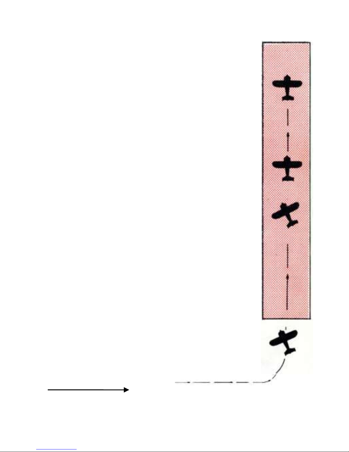
CROSS WIND TAKEOFF IN
AN ERCOUPE
START AT THE
BOTTOM AN READ UP
In taking off cross wind, it
is advisable to keep the
control wheel well forward,
which holds the nose wheel
firmly on the ground and
gives good steering control.
Some excess in forward
speed should be gained to
allow the airplane to take
off very definitely, and at
the moment of breaking
contact with the ground,
the control wheel should
be straightened laterally to
a neutral position. The air-
plane may weathercock
into the wind just after it
leaves the ground but this
need cause no concern as it
is merely adjusting itself to
true flight with respect to
the air, and a straight
course of travel is
maintained without
difficulty. The pilot should
not hesitate to make slight
turns near the ground in
order to maintain the
desired path and avoid
being drilled off course by
the wind.
4. A straight course of flight
is maintained on the center
line of runway during the
climb. If the plane drifts
sideways, make slight turns
to get back to center of
runway
3. The airplane weather-
cocks into the w ind just
after leaving the ground.
Wings are held level.
2. Gain some excess
forward speed and take off
very definitely. At the
moment of breaking contact,
straighten the control wheel
laterally to a neutral
position.
1. On ground run, keep
forward pressure on the
control wheel and some
right control necessary to
overcome weathervaning
(tendency to head into the
wind )
WIND FROM THE LEFT
13
CROSS WIND LANDING IN
AN ERCOUPE
START AT THE
BOTTOM AN READ UP
In the approach to a cross
wind landing, the airplane
will be pointing up wind
sufficiently to keep the flight
path in line with the runway
rather than attempt to drop
the windward wing as is
done in the three control
plane. The glide should be
continued in this crabbing
attitude down until contact
is made with the ground. At
the moment of contact the
airplane should be given its
head, and the grip on the
control wheel relaxed. This
allows the nose wheel to
caster and line up with the
direction of motion of the
airplane along the ground.
Immediately thereafter, ease
the control wheel forward
slowly and roll down the
runway. Prompt application
of the brakes or setting the
brake on about half way
during the glide approach
brings the nose down and
completes the change in
heading more quickly
5. During ground run steer
like a car.
4. On ground plane will
change heading to line up
with path along runway.
3. Make contact decisively
at low speed with plane
still crabbed, but relax grip
on control wheel to allow
nose to caster and ease
forward on control wheel
slowly
2. If plane drifts sideways,
make slight turns to get
back to center line of
runway
1- Finish turn with
Ercoupe on extended cen-
terline of runway and
headed or crabbed into
wind just enough to keep
its flight path (not head-
ing} on the extended
centerline.
WIND FROM THE LEFT

14
COCKPIT CHECK LIST
STARTING
1. Check quantity of fuel and oil
2. Both fuel valves ON
3. Mixture—FULL RICH at all times
4. Carburetor Air heat OFF
5. Prime 2 to 6 strokes—Lock Plunger
6. Throttle - Crack 1/8 inch
7. Ignition on - Pull Starter
8. Warm up - 900 to 1200 RPM
BEFORE TAKE-OFF
1. Carburetor Air Heat Off (use full heat in icing conditions)
2. Oil temperature - 90⁰F min
3. Oil pressure - >35 lb/sq inch (above 1900 RPM).
4. Full throttle - 2000 RPM approximately
5. Ignition Check - maximum 75 RPM drop on either magneto
and with Carb Heat
6. Check for good idle
FLIGHT
1. Oil pressure - >35 lbs
2. Oil temperature range 100⁰to 220⁰F
3. Adjust mixture control for best RPM (ABOVE 5000 FT.)
LANDING
1. Mixture control- FULL RICH.
2. Open throttle periodically in glide to clear cylinders

15
SERVICE AND INSPECTION INSTRUCTIONS
PARTS AND ADJUSTMENTS
Genuine ERCOUPE replacements parts are available only through
authorized Distributors and Dealers. These representatives have a
stock of the most needed repair parts and a file of information for
the repair and adjustment of the ERCOUPE The nearest dealer may
be determined from the list in the back of this book. He should be
contacted for needed service.
The ERCOUPE owner should write the distributor or dealer in his
territory and request that he be put on the mailing list to receive
any special notice for ERCOUPE owners. This will assure him
immediate advice should changes or modifications in his airplane
be recommended.
The serial number on the nameplate fastened on the deck behind
the baggage compartments should be included in all
correspondence requesting information or parts for the ERCOUPE.
WINDSHIELDS AND WINDOWS
Flush off the excess dirt and grit with clear water and then use a
soft, grit free sponge or open-mesh cheese cloth and mild soap. All
rubbing should be done as lightly as possible to avoid scratching.
Do not use glass cleaning solutions, as they may contain solvents
that are harmful to plastic.
ALUMINUM
Remove all loose dirt and grit from surface so that it will not be
scratched when cleaner is applied. Wet a pad of Turkish toweling
with aluminum cleaner and rub surface until cleaner has mixed
with and absorbed all foreign matter. Wipe off remaining polish
with a soft dry cloth.

16
OUTER PANEL WING COVER
The original high luster finish can be preserved, and the life of the
covering can be lengthened by observing the following;
1. Rinse off the excessive dirt with clear water and then wash
with a mild soap.
2. To restore the luster, polish with a mild rubbing compound
and coat with wax (Avoid rubbing too hard on covering at
sharp edges).
TIRES - MAIN WHEELS
It is necessary to remove the wheel hub cap to reach the valve stem
for pumping up the tires In removing tire proceed as follows:
1. Remove hub cap.
2. Remove nuts that hold wheel halves together.
3. Remove axle nut.
4. Pry bead of tire loose.
5. Remove outer wheel half and tire Leave inner wheel half
remaining on axle.
TO INSTALL TIRE, REVERSE REMOVAL PROCEDURE
TIRE - NOSE WHEEL
In removing tire proceed as follows:
1. Remove nuts that hold wheel halves together
2. Have someone hold tail down to lift nose wheel
3. Pry bead of tire loose
4. Remove outer wheel half and tire. Leave inner wheel half
remaining on axle
TO INSTALL TIRE, REVERSE REMOVAL PROCEDURE
BRAKE
The brake fluid reservoir is located under the hood on the firewall
and should be kept nearly full of fluid. Excessive lost motion in the
operation of the hand control should be eliminated by adjustment
of the clevis at the end of the control wire. However, be sure that
the master cylinder returns its full travel.

17
The brakes do not require adjustment of the lining surfaces.
To bleed the brake system
1. Fill the reservoir with fluid.
2. Remove the bleeder screw from fitting on one side only of the
wheel brake assembly and place finger lightly over the hole.
3. Have someone operate the brake control to full on" then hold
finger over hole firmly and return control to "off" position.
Allow a few seconds for the fluid to flow into the master
cylinder and repeat the operation several times. Be sure to
keep the reservoir full during this operation.
4. Install the bleeder screw.
5. Remove the bleeder screw from the other side and repeat
operation (3)
6. Install the bleeder screw.
7. Continue bleeding until brake has a solid feel when applied.
Note: Do not allow hydraulic brake fluid to get on linings. Wash
clean with carbon tetrachloride or naphtha.
CONTROL SYSTEM
To Check Control System Alignment:
1. Neutralize the control wheels and check the control mast
under the baggage compartment to be sure the arms are also
neutral.
2. This should place the ailerons in line with the wing airfoil
section.
3. In neutral, the nose wheel should also line up straight with the
centerline of the airplane.
4. Now check rudders (everything inneutral) using two
straightedges paralleling the fin. Both should be straight.
5. Elevator limits are fixed by contact of a stop ring placed on the
control wheel tube with the instrument panel and should
permit 13⁰ ±1⁰ up travel. The up travel of the elevator is
controlled by a turnbuckle which is sealed at the factory with a

18
lead seal. This seal must not be broken except by an
authorized ERCOUPE Service Station who will reseal it after
making any necessary adjustment
STEERING LINKAGE
If shimmy occurs in the nose wheel while the airplane is running
along the ground, it is an indication of looseness in the joints of the
steering linkage, or of tire unbalance To eliminate the shimmy
remove the excess play and balance the tire on the wheel
PROPELLER
The propellers approved for the ERCOUPE are the Sensenich
design 74FCT 48 (for the taper shaft) and the 74FKT 48 (for the
flanged shaft). Both are fitted with extra durable stainless steel
leading edge tipping. Either propeller can be altered to fit the other
type shaft, by a properly equipped shop.
Watch for signs of wear and dents on the leading edges or
scratches which expose the wood and permit the absorption of
moisture. Bare spots should be sanded and sealed with spar
varnish. Moisture entering through exposed wood will cause
roughness by disturbing the weight balance. Any large repair will
require the propeller to be balanced and should be made by an
approved repair station
ENGINE IDLING SPEED
After the engine is warmed, and with the throttle fully closed, the
engine should maintain 650 RPM on the tachometer. With a lower
idling RPM the engine may stop in a slow glide
MAGNETO AND SPARE PLUG CHECK
With the engine warmed, the magnetos should be tested separately
for proper firing. Revolution speed of engine with full throttle
should not drop off more than 75 RPM on either single magneto
from operation with both magnetos. Prolonged full throttle
operation on the ground should be avoided.

19
ENGINE COMPRESSION CHECK
While the engine is warm and with the ignition switch turned "off,"
pull the motor through four complete compression strokes to check
for weak compression of any cylinder. An indication of poor
compression should be checked with a competent engine man for
his final decision.
Note: Do not pull engine through by hand immediately after
running, as the engine may start
IGNITION SWITCH
The switch key is numbered and this number should be recorded in
the log book for future reference in ordering duplicate keys.
FUEL SYSTEM
The engine driven fuel pump moves fuel from the wing tanks to the
six gallon fuselage header tank. Excess fuel drains from the header
tank overflow line back to the wing tanks. Fuel is gravity feed from
the header tank to the engine carburetor. In case of fuel pump
failure, the engine will continue to function until the six gallon
header tank is empty.
The Main Fuel Valve is located approximately halfway between the
brake handle and the pilot's control wheel shaft under the
instrument panel. This main valve should be ON (lined up with
down pipe) at all times except in case of an emergency.
The Wing Tank Shut-Off Valve is located on the right side skin
forward of the seat. The valve handle should be ON (lined up with
fuel line) and secured with a piece of brass safety wire. The only
time this valve should be off is in a case of emergency or a
malfunction. If the valve is turned OFF, the fuel cannot be pumped
from the wing tanks to the header tank and the engine fuel supply
and the remaining flying time, is limited to what fuel remains in the
header tank.

20
Wing tank caps should be checked for good gaskets and functioning
vent.
The wing tank gauge indicates the quantity of fuel in both wing
tanks as a fraction of 18 gallons. The gauge is located close to the
floor on the pilots side of the cockpit.
The header tank gauge, located forward of the windshield, is a
visual check of the remaining fuel in the header tank. When the
gauge is fully up there are six gallons in the tank. When it reaches
the fully down position, at least one gallon should be left in the
tank. Check the condition of the float frequently to ensure proper
reading from this gauge.
FUEL SYSTEM
Table of contents
Popular Tools manuals by other brands

Vela
Vela 011725 Mounting instructions

Trick-tools
Trick-tools Hougen-Ogura PUNCH PRO 75006PR Operator's manual

Utility Solutions
Utility Solutions Jack Jumper USJJ-004 quick start guide

BGS technic
BGS technic 9414 instruction manual

ATD Tools
ATD Tools ATD-81045 Operating instructions & parts manual

Clas Ohlson
Clas Ohlson 40-8674 Mounting


