Eni 240L Operation manual

240L Broadband Power Amplifier

EN!
OPERATION &SERVICE MANUAL
240L
Broadband Power Generator
WARNING fHIGH RF VOLTAGES MAY BE PRESENT AT THE OUTPUT OF THIS
UNIT. All operating personnel should use extreme caution in handling these voltages and be
thoroughly familiar with this manual.
DO NOT USE ANY CFG (CHLOROFLUOROCARBON) SOLVENT IN THE
MAINTENANCE OF THIS PRODUCT. In recognition of our responsibility to protect
the environment, this product has been manufactured without the use of CFC's. The no-clean
flux now used in all soldering operations may leave asmall inert residue which will not affect the
performance of the product. The use of CFC’s for cleaning or maintenance may result in partial
Uquification of the no-clean flux residue, which will damage the unit and void the warranty.
Notice •
The material contained in this manual is subject to change without notice. No part of this manual may be reproduced or
utilized in any form or by any means, electronic or mechanical, including photocopying or electronic transmission or
other means of reproduction or distribution without prior written consent of ENI. The drawings, specifications and
other technical information contained in this manual are the property of ENI and shall not be copied, reproduced or used
in any way, in whole or in part, as the basis of manufacture or sale of similar items without the prior written consent
of EI^.
Manual Order Number: 240L-TM
Revision Level: ACopyright ©1992 ENI. All rights reserved.
Printed in the USA.

ENI warrants to the original purchaser for aperiod of one year from the date of delivery, each instrument to be free from
defects in materials and workmanship. For aperiod of one year, ENI will, at its option, adjust, repair, or replace defective
parts, without charge to the original purchaser, so that the instrument performs according to its specifications.
When warranty service is required, the instrument must be returned, transpOTtation prepaid, to the factory or to one of ENTs
designated service centers. If, in our opinion, the instrument has been damaged by accident, unreasonable use, buyer-supplied
software or interfacing, improper site preparation or maintenance, or abnonnal conditions of operation, repairs will be billed
at standard rates. In this case, an estimate will be submitted before the work is started.
THIS LIMITED WARRANTY IS EXCLUSIVE AND ENI MAKES NO OTHER WARRANTIES. EXPRESS OR IMPLIED, AND ALL OTHER
EXPRESS ORALOR WRITTEN WARRANTIES AND ALL WARRANTIES IMPLIED BY LAW, INCLUDING ANY WARRANTIES OF
MERCHANTABILITY OR FITNESS K)R APARTICULAR PURPOSE OR OTHER WARRANTY OF QUALITY AREEXCLUDED AND
DISCLAIMED. IN NO EVENT SHALL ENI BE LIABLE FOR SPECIAL, INDIRECT, INCIDENTAL OR CONSEQUENTIAL DAMAGES
RESULTING FROM BREACH OF ANY WARRANTY. WHETHER EXPRESS OR IMPLIED, INCLUDING ANY IMPLIED WARRANTY
OF MERCHANTABIUTY OR FITNESS FOR APARTICULAR PURPOSE, OR FROM ANY CAUSE WHATSOEVER. INCLUDING
NEGLIGENCE. Buyer’s sole and exclusive remedy under this warranty shall be repair or replacement as set forth above, or if
ENI is unable to repair or replace the defective part within areasonable time, arefund of the price of the part or goods which
give rise to the warranty claim.
Service and Technical Assistance
For Technical Support for your particular application, contact the nearest ENI Sales and Service Center. The following
information will help us provide you with prompt and efficient service:
•All of the information contained on the unit’s name plate.
•Detailed description (i.e. physical damage and/or performance anomalies, quantitative and/or qualitative deviation from
specifications), including miscellaneous symptoms, dates and times.
•The environment and circumstances under which the issue developed.
•Names and telephone numbers of important contacts.
•Supporting test data and/or records that can be provided.
•Any previous, related conversations and/or correspondence with ENI.
For Service or Repair contact the closest Customer Service Department with the following information:
•Model and serial number
•Detailed description of malfunction
•hirchase order number
•Your company’s "BUI To" and "Ship To" address
You wUl receive aRMA (Return Materials Authorization) number, the wananty status of the unit to be returned and
estimated repair charge, if any. The RMA number is your authorization number. Please type this number on your purchase
order and shipping label. After ENI receives the unit, afirm quote and estimated date of completion will be given.
ENI East Coast
ENI West Coast
ENI Europe
ENI Germany
ENI Japan
Sales and Service Locations
ADivision of Astec America, Inc., 100 Highpower Road, Rochester, NY 14623
Tel: (716) 427-8300 Fax: (716) 427-7839 Service: (716) 292-7478
2065 Martin Ave., Suite 101, Santa Clara, CA 95050
Tel: (408) 727-0993 Fax: (408) 727-1352
Mundells Court,Welwyn Garden City, Hertfordshire AL lEN England
Tel: (0707) 371558 Fax: (0707) 339286
Holderackerstrasse 14, D-7016 Geriingen, Germany
Tel: 07156-21095 Fax: 07156-49372
541 Aoyogi, Kunitachi, Tokyo 186, Japan
Tel: 0425 22901 1Fax: 04025 222636
Fujita Bldg 4F, 2-27 Nishitenmna 3-chome, Kita-Ku, Osaka 530, Japan
Tel: 06-367-0823 Fax: 06-367-0827
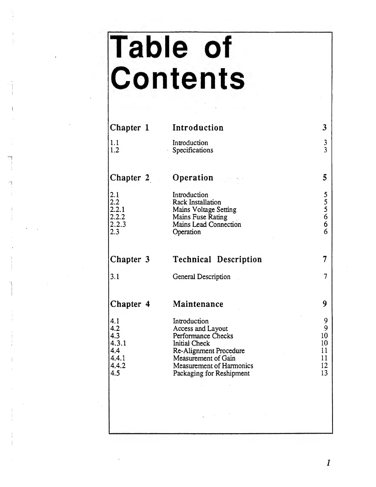
Chapter 1Introduction 3
uIntroduction 3
1.2 Specifications 3
Chapter 2
2.1
2,2
2.2.1
2.2.2
2.2.3
2.3
Operation
Introduction
Rack Installation
Mains Volage Setting
Mains Fuse Rating
Mains Lead Connection
Operation
5
5
5
5
6
6
6
Chapter 3Technical Description 7
3.1 General Description
Chapter 4Maintenance 9
4,1 Introduction 9
4.2 Access and Layout 9
4,3 Performance Checks 10
4.3.1 Initial Check 10
4.4 Re-Alignment Procedure n
4.4.
1
Measurement of Gain 11
4.4.2 Measurement of Harmonics 12
4.5 Packaging for Reshipment 13
»n
»n
VO
VO
VO
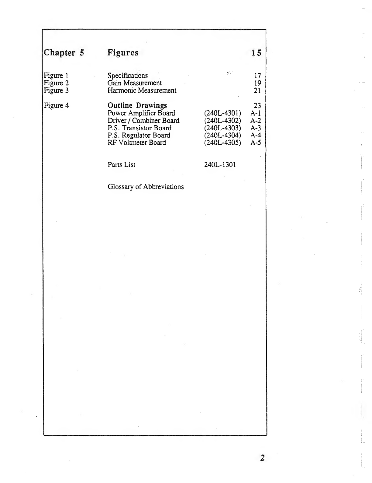
Figures 15
Figure 1
Figure 2
Figure 3
Figure 4
Specifications
Gain Measurement
Harmonic Measurement
Outline Drawings
Power Amplifier Board
Driver /Combiner Board
P.S. Transistor Board
P.S. Regulator Board
RF Voltmeter Board
17
19
21
23
(240L-4301) A“1
(240L-4302)
(240L-4303) A-3
(240L-4304) A*^
(240L«4305) A-5
Parts List 240L- 1301
Glossary of Abbreviations

1.1 Introduction
The Model 240L is abroadband solid state power amplifier covering the frequency
range of 20 kHz to MHz.
More than 40W of RF power can be produced at the output, with low harmonic and
intermodulation distortion. Up to 200W of saturated power can be produced with
increased distortion products. Ahighly linear Class Adesign, the Model 240L will
amplify inputs of AM, FM, SSB, pulse and other complex modulations. The 50 dB
gain of the unit is unconditionally stable and will not oscillate for any possible
combination of source and load impedance. It is protected against failure due to
output load mismatch and/or overdrive.
Output RF voltage level, as well as power output into 50 O, is monitored by afront
panel meter. An integral power supply permits operation from 115/230 single phase
AC power.
Specifications
Physical and electrical specifications are listed in Figure 1.

Chapter 2
Operation
2.1 Introduction
The ENI 240L RF amplifier is used to increase the r.f. output level of signal sources
in the 20 kHz to 10 MHz range. No tuning or any other form of adjustment is
required other than the selection of the correct power supply input voltage.
The 240L produces rated power output connector, regardless of load impedance.
Any power reflected due to output load mismatch is absorbed in the amplifier.
Therefore, although the output impedance is 50 O(typical VSWR: 1.5:1), the
amplifier will work into any load impedance.
2.2 Rack Installation
For standard nineteen inch relay rack installations, rack mounting brackets are
supplied with the unit. Remove the two #8>32 screws on each side of the cover
nearest the front panel. Attach the rack mounting brackets firmly using the hardware
removed above. The rubber feet may be unscrewed and removed if the minimum
vertical usage of the relay rack is necessary.
2.2.1 Mains Voltage Setting
The supply voltage selection switch is located at the rear of the instrument and is
normally set for 115 VAC operation.
Before connecting the unit to the mains supply, check that the supply voltage
selection switch is correctly set. Extensive damage will result if the Amplifier is
connected to the wrong supply voltage. Under no circumstances should this
switch be operated while the supply is connected.

2,J2i,2i
2.2.3
2 3
The mains fuse FI is located on the rear panel. The replacement part number details
are:
115 V8amp Slow Blow ENl Part No. 313008
230 V4amp Slow Blow ENI Part No. 313004
Mains Lead Connection
For 230 VAC operation, asuitable mains supply plug must be fitted to the mains lead
attached to the instrument The three conductors are color coded as follows:
BLACK -Live
WHITE -Neutral
GREEN •Earth
Operation
Determine and adjust the voltage setting and fuse rating as described in the previous
sections 2.2.1 and 2.2.2 then proceed as follows:
(i) Ensure input voltage is not excessive
The 1Vrms indicated maximum input voltage is 5times the level of the input
signal required to achieve maximum output. Input voltages in excess of 2V
peak may permanently damage the instrument.
(ii) Connect the input signal via a50 Ocoaxial lead and BNC plug to the input
connector.
(iii) Connect the output via a50 Ocoaxial lead and BNC plug to the load.
6
Chapter 3
Technical Description
3.1 General Description
The ENI 240L is designed to amplify signals by 50 dB in the frequency band 20 kHz
to 10 MHz. The signS from the front panel BNC connector is fed via alength of
50 Q. coaxial cable into the input of the driver/combiner module (240L-4302). The
signal at the collector of Q1 is amplified further by transistor Q2. The output signal
at the collector of Q2 is then split into two equal phase and amplitude signals by
transformer T2. The two output signals from T2 are fed to the bases of Q3 and Q4,
The output signals of transistors Q3 and Q4 are combined in transformer T3,
impedance matched in transformers T4 and T6 and split into to equal phase and
amplitude signals by transformer T7. These output signals are fed to connectors- J3
and J4 which are fed via coaxial cables to the inputs of the two power amplifier
modules (240L~4301).
The signal applied at J5 is impedance matched and split into two equal phase and
amplitude signals by transformers T1 and T2. The signals at the outputs of T2 are
split and phase reversed by transformers T3 and T4. The outputs of transformers T3
and T4 are fed to the bases of Ql, Q2 and Q3, Q4 respectively. The power outputs
of Q1 and Q2 are combined in the phase reversing transformer T5 and the power
outputs of Q3 and Q4 are combined in phase reversing transformer T6. The output
signals from T5 and T6 are combined and impedance matched to 50 Qat the output
connector J7 by transformers T7 and T8.
The output signals from the two power amplifier modules (240L-4301) are fed via
coaxial cables to J9 and JIO of the driver/combiner module (240L-4302). These two
signals are combined by hybrid transformer T8. Capacitor Cl 8and transformer T9
match the combined RF output signal to 50 Q. at connector J1 1. The output signal is
fed via a50 Hcoaxial cable to the RF voltmeter module J12 (3100L-4206).
The signal at J12 is connected via alength of microstrip transmission line to the
output BNC connector J13. Off of this microstrip line resistors Rl, R2, R3 and R4
make up ahigh impedance voltage divider. Afast switching hot carrier diode CRl
rectifies the RF voltage from the divider. Awire gimmick (capacitor C2)
compensates for the high frequency roU-off of the diode CRl. Resistors R4, R5, R6
and capacitor Cl filter the rectified RF and convert it to DC which is fed to the front
panel meter (Ml).
The amplifier power requirements are 115 Vor 230 VAC. at 450W. The power
supply unit provides a36 VDC, 7.0A source and a21VDC 40 mA source. The
36VDC source is regulated by series pass transistors Ql, Q2, Q3 and Q4 and
integrated circuit regulator ICl. R3 adjusts the supply to 36V. The front panel light
and the RF voltmeter are connected to the 21 VDC source and the lamp will indicate
when the power supply is operating correctly.

4.1 Introduction
The EMI 240L RF amplifier requires no periodic maintenance. The instrument is
unconditionally stable and is failsafe under ail load conditions. Damage can only be
extemaBy caused by the incorrect selection of the supply voltage or by an input signal
in excess of the specified IV rms maximum.
This chapter therefore, deals only with certain fundamental procedures for fault
location and with the subsequent re-alignment procedures.
Performance limits quoted are for guidance only and should not be taken for
guaranteed performance specifications unless they aie also quoted in Figure 1.
4.2 Access and Layout
The ENI 240L RF amplifier is housed in an aluminum chassis. The cover can be
removed by releasing the eight #8-32 screws on the side of the unit and the eight #4-
40 flat head Phillips head screws on the top of the unit and lifting by the handle.
The rear panel supports the mains fuse holder, the mains input voltage selector
switch (S2) and the cooling fan.

4.3 Performance Check
To determine the amplifier’s performance carry out the following procedure.
4.3.1 Initial Check
The following check can be made after repair and adjustments or whenever the
condition of the unit is in question.
(i) Connect power supply. Switch on power and observe that the supply
lamp (DSl) illuminates.
(ii) Connect asweep generator (HP 8601 or similar) capable of sweeping
the frequency range 20 kHz to 10 MHz to the input connector.
(iii) Adjust the output level of the sweep generator so that a50 Ovideo
detector connected at the output of the unit wiU not be damaged by
excessive power output.
(iv) Observe the gain versus fluency ripple on an oscilloscope calibrated
in decibels. The gain variation must be not more than ±1.5 dB over
the frequency range.
(v) Connect acalorimetric power meter (HP434 or equivalent) through a
10 dB lOOW attenuator to the output connector. Adjust the input
CW signal to any frequency between 20 kHz and 10 MHz for
40W output.
(vi) Observe the harmonic distortion of the output of aspectrum analyzer.
Ifre harmonic components contributed by the amplifier should be at
least 25 dB down from the fundamental.
If the requirements of this check are not met, verify that:
(a) The mains supply switch and fuse are correctly selected and that DSI
is illuminated.
(b) The power supply voltage is set at 36V by R3.
If the above checks are found to be correct, then normal fault location procedures,
with reference to the circuit diagram Reference 1should be followed to determine the
correct operation of the driver/combiner and power amplifier modules.
10
4*4.X
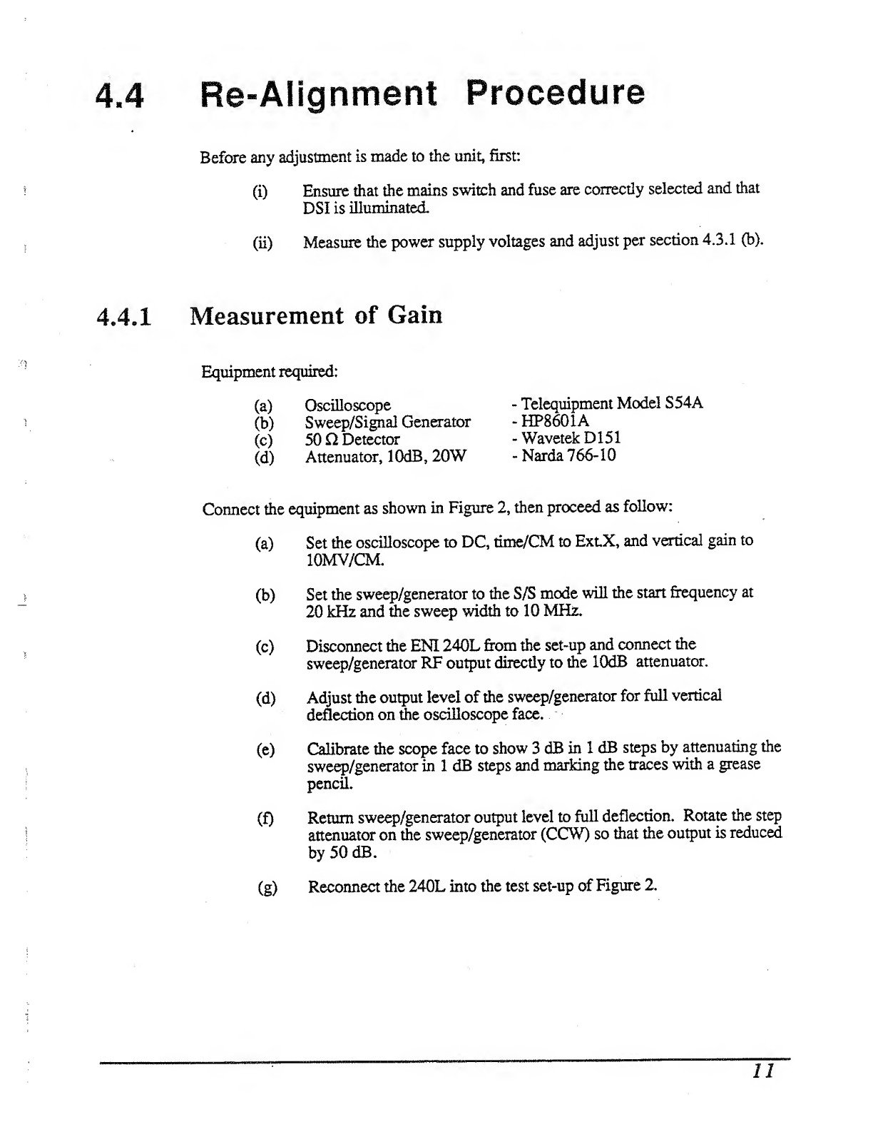
Before any adjustment is made to the unit, first:
(i) Ensure that the mains switch and fuse are correctly selected and that
DSI is illuminated
(ii) Measure the power supply voltages and adjust per section 4.3.1 (b).
Measurement of Gain
Equipment required:
(a) Oscilloscope
(b) Sweep/Signal Generator
(c) 50 nDetector
(d) Attenuator, lOdB, 20W
-Telequipment Model S54A
-HP8601A
~Wavetek D151
-Narda 766-10
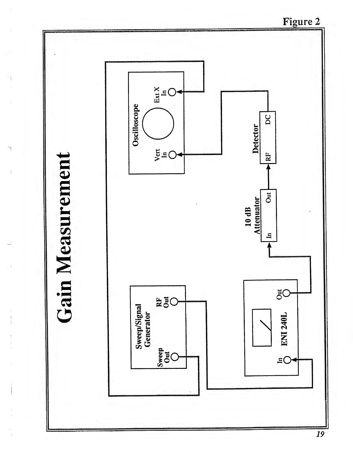
Connect the equipment as shown in Figure 2, then proceed as follow:
(a) Set the oscilloscope to DC, time/CM to ExtX, and vertical gain to
lOMV/CM.
(b) Set the sweep/generator to the S/S mode will the start frequency at
20 kHz and the sweep width to 10 MHz.
(c) Disconnect the ENI 240L from the set-up and connect the
sweep/generator RF output directly to the lOdB attenuator.
(d) Adjust the output level of the sweep/generator for full vertical
deflection on &e oscilloscope face,
(e) Calibrate the scope face to show 3dB in 1dB steps by attenuating the
swe^/generator in 1dB steps and marking the traces with agrease
pencil.
(f) Return sweep/generator output level to full deflection. Rotate the step
attenuator on the sweep/generator (CCW) so that the output is reduced
by 50 dB.
(g) Reconnect the 240L into the test set-up of Figure 2.
I

(h) Place the 240L power switch to the "on” position.
(i) Observe the gain versus frequency sweep on the oscilloscope.
1.The average gain should by 50 dB (within 1dB).
2. The gain variation should be within the 3dB markings as
shown on the oscUioscope.
4.4.2 Measurement of Harmonics
Equipment required:
(a) Sweep/signal generator HP8601A
(b) Attenuator, 30 dB Bird 8321
(c) Calorimetric Power Meter HP434A
(d) Spectrum Analyzer HP140T Display Unit
HP8554L Spectrum Analyzer
RF Section
HP8552A Spectrum Analyzer
IF Section
(e) Attenuator, lOdB Bird 8341
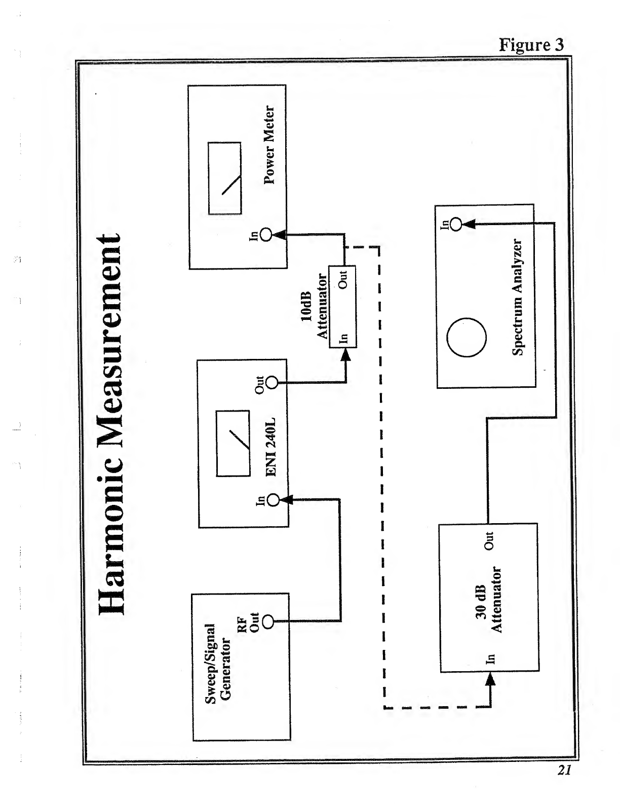
Connect the Equipment as shown in Figure 3then proceed as follows:
(a) Adjust the sweep/signal generator at aCWcenter j&equency of 4MHz
for an indicated output of 40W on the power meter.
(b) Using the spectrum analyzer, check that the level of the carrier
harmonics less than -25 dB with respect to the carrier.
12
In the event of the equipment being returned for servicing it should be packed in the
original shipping carton and packing material. If this is not available, wrap the
instrument in heavy paper or plastic and place in arigid outer box of wood,
fiberboard or very strong corrugated cardboard. Use ample soft packing to prevent
movement. Provide additional support for projecting parts to relieve these of
uimecessary shock. Close the carton securely and seal wiA durable tape. Mark the
shipping container FRAGILE to ensure careful handling.
13

Figure 1Specifications page 17
Figure 2Gain Measurement 19
Figures Harmonic Measurement 21
Figure 4Outline Drawings: 23
Power Amplifier Board (240L-4301) A-1
Driver /Combiner Board (240L-4302) K-2
P.S. Transistor Board (240L-4303) A-3
P.S. Regulator Board (240L-4304) A~4
RF Voltmeter Board (240L-4305) A-5
Glossary of Abbreviations

240L Specifications
Frequency Coverage:
Gain:
Class ALinear Output:
Harmonic Distortion:
Saturated RF Power Output:
Input/Output Impedance:
Noise Figure:
Stability:
Protection:
Output Meter:
20kHz to lOMHz
50dB, ±1.5 variation
40 Watts
Typically more than 28dB below fundamental at
40 Watts output.
Greater than 50 Watts
20kHz to lOMHz
Greater than 100 Watts
30kHz to 4MHz
Greater than 150 Watts
40kHz to 2MHz
500, VSWR 1.5 maximum
8dB maximum
Unconditionally stable
Unit will withstand more than 16dB overdrive for
all output load conditions.
Average reading voltmeter calibrated in volts (0-
lOOV) also calibrated in watts into 500 (0-200W),
±5% accuracy.
Power Requirements: 115-230VAC ±8% at 450 Watts
Size: 7X10 X16.5 inches
17.8x25.4x41.9 cm.
Weight: 35 pounds
15.9 kg
Connectors:
17

Outline Drawings
A. Power Amplifier Board (240L-4301) AA
B. Driver /Combiner Board (240L4302) A**2
C. P.S. Transistor Board (240L-4303) A-3
D. P.S. Regulator Board (240L-4304) A4
E. RF Voltmeter Board (240L-4305) A-5
Parts List 240L-1301
23
Other manuals for 240L
1
Table of contents
Other Eni Amplifier manuals


