UNISENSE UniAmp fx-6 User manual

Unisense UniAmp Multichannel Systems
User Manual
UNIAMP MULTICHANNEL SYSTEM MANUAL
Copyright © Unisense A/S
Version 1.1, August 2020

2
Table of Contents
1 Scope of the manual .......................................................................................................................3
2 Warranty and liability .....................................................................................................................3
2.1 Repair or adjustment..............................................................................................................3
3 Support, ordering, and contact information...................................................................................3
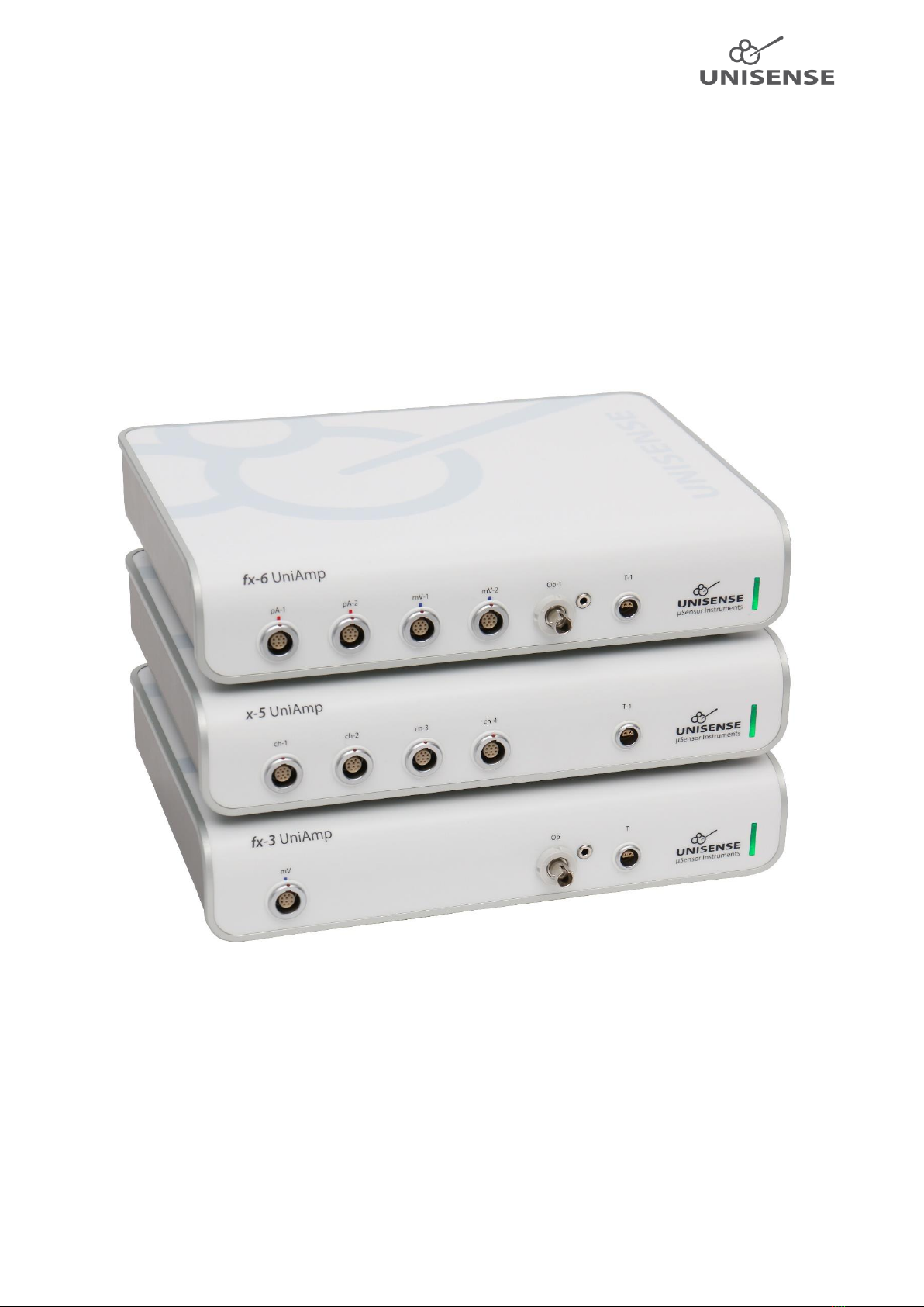
4 Overview.........................................................................................................................................3
5 Operating and setup conditions .....................................................................................................4
6 Installation and setup of UniAmp and software.............................................................................4
6.1 Installation of the SensorTrace Suite software.......................................................................5
6.2 Connect the UniAmp to the PC...............................................................................................5
7 Getting started................................................................................................................................6
7.1 Connecting sensors with automatic settings..........................................................................6
7.2 Manually setting the Pre-amplification ..................................................................................6
7.3 Manually setting the sensor polarization ...............................................................................6
7.4 Adjusting the offset.................................................................................................................7
7.5 Setting STOX sensor parameters ............................................................................................7
7.6 Polarizing amperometric sensors without a PC connected....................................................8
8 Sensor connections and compatibility............................................................................................8
8.1 Sensors, connectors, and adaptors.........................................................................................8
8.2 Grounding ...............................................................................................................................8
8.3 Software..................................................................................................................................9
9 Analog in and out............................................................................................................................9
10 Digital in and out.........................................................................................................................9
11 Auxiliary equipment..................................................................................................................10
12 Temperature compensation .....................................................................................................10
12.1 Electrochemical sensors........................................................................................................10
12.2 Oxygen optodes ....................................................................................................................11
13 Troubleshooting........................................................................................................................11
13.1 Problems logging over long periods of time.........................................................................11
13.1.1 Windows Update ..........................................................................................................11
13.1.2 Loss of connection to the UniAmp because of USB power saving ...............................12
13.1.3 Disable power saving on the PC....................................................................................12
13.2 Electrical noise ......................................................................................................................12

3
1Scope of the manual
This manual covers the multichannel versions of the UniAmp: fx-6 UniAmp, x-5 UniAmp, fx-3
UniAmp, and the customized multichannel versions.
2Warranty and liability
The UniAmp meters are covered by a one-year warranty.
The warranty does not include repair or replacement necessitated by accident, neglect, misuse,
unauthorized repair, or modification of the product.
In no event will Unisense be liable for any direct, indirect, consequential or incidental damages,
including lost profits, or for any claim by any third party, arising out of the use, the results of use, or
the inability to use this product.
2.1 Repair or adjustment
Equipment that is not covered by the warranty will, if possible, be repaired by Unisense with
appropriate charges paid by the customer. In case of return of equipment please contact us for
return authorization.
For further information please see the document General terms of sale and delivery of Unisense A/S
as well as the manuals for the respective products.
3Support, ordering, and contact information
If you wish to order additional products or if you encounter any problems and need scientific or
technical assistance, please do not hesitate to contact our sales and support team. We will respond
to your inquiry within one working day.
Unisense A/S
Tueager 1
DK-8200 Aarhus N, Denmark
Tel: +45 8944 9500
Fax: +45 8944 9549
Further documentation and support may be found at www.unisense.com
4Overview
The multichannel UniAmp meters are compact and economical meters for the Unisense
electrochemical microsensors, including the STOX sensors and optodes.
The meters come with different number and combination of channels. The channels are labelled:
•pA (Pico ampere) for amperometric sensors (O2, N2O, H2, H2S, NO, STOX)
•mV (millivolt) for potentiometric sensors (pH, redox)
•Op (optical) for oxygen optodes
•T(temperature) for temperature sensors

4
The standard multichannel UniAmp come in the following configurations:
•fx-6 UniAmp (2 x pA, 2 x mV, 1 x Op, 1 x T)
•x-5 UniAmp (2 x pA, 2 x mV, 1 x T)
•fx-3 UniAmp (1 x pA or 1 x mV, 1 x Op, 1 x T)
Figure 1: fx-6 UniAmp
All amperometric channels (pA) have support for the ultrasensitive STOX oxygen sensor with a
detection limit of <10 nM.
The fx6 and x-5 UniAmp are also available in customized versions, with the combination of channels
decided by the customer.
The meters offer temperature compensation for all amperometric channels with a range of ± 3°C
from the calibration temperature. This will work if a temperature sensor is connected.
The UniAmp meters are USB-powered and fully integrated with the Unisense SensorTrace Suite
software, allowing any combination of Unisense electrochemical sensors and optode technology.
The user interface consists of a pop-up window (a Microsoft Windows service) that is installed in the
Windows Notification Area, also called System tray, in the lower right hand area of the screen. Using
this pop-up, you can adjust channel settings such as pre-amplification, offset, sensor polarization etc.
5Operating and setup conditions
The UniAmp meters are designed for laboratory use. Care must be taken to protect the amplifiers in
humid, dusty, and corrosive environments (e.g. field conditions) since it may affect the performance,
cause damage, or shorten lifetime. If the amplifier is used outdoors, it should be protected in a
plastic bag or similar.
Temperature: 0 to +50°C (<90% rel. humidity, non-condensing)
Power: From PC, through the USB cable
Grounding: Through the USB cable. Ensure that the PC is properly grounded.
6Installation and setup of UniAmp and software
The UniAmp instruments must be used with the SensorTrace Suite software. Install the latest version
of the software, which can be downloaded from https://www.unisense.com/Software_download/.
The Logger and Programming Tool parts of the software suite are freeware, whereas Profile, Rate,
and Photo require a license. The SensorTrace Suite is compatible with Windows versions 7 and 10.

5
6.1 Installation of the SensorTrace Suite software
Locate the SensorTrace Suite Setup file on your PC.
•Right-click on the file and select Run as administrator
•If you get the message Windows protected your PC, click More info
oClick Run anyway
•If you get the message Do you want to allow this app to make changes to your device? click
Yes
•In the SensorTrace Suite Setup window, accept license terms and conditions and click Install
•Follow the instruction on the screen to complete the setup
•If you have purchased a license, start one of the Suite applications (Logger, Profile, Rate,
Photo), click Help - Register license
6.2 Connect the UniAmp to the PC
Connect the UniAmp to the PC using a USB-A to USB-C cable. The drivers needed for connection will
automatically be installed. The Unisense UniAmp service is installed together with the SensorTrace
Suite. Click on the UniAmp service icon to open a window with a frame for each sensor connected to
the UniAmp (Figure 2).
NOTE: Only channels with a sensor connected will be shown!
The UniAmp instruments are powered through the USB cable and no external power supply is
needed.
NOTE: The USB cable must be a high quality shielded cable!
Figure 2: Unisense UniAmp service in the Windows Notification Area. Click the up-arrow to show hidden icons, then click the
UniAmp service icon to open it. Only channels with a sensor connected, will be shown. Here sensors for H2S, pH and O2are
connected and shown. For each channel, the UniAmp Channel Configuration window may be opened by clicking the three
grey lines (red circles), see Figure 3.
Click to open the
UniAmp Channel
Configuration window

6
7Getting started
The UniAmp instruments are powered from the PC through the USB cable and are operated through
the Unisense UniAmp service in the Notification Area (Figure 2). Just connect the UniAmp to the PC
and settings for the connected sensors will be available in the UniAmp service window.
7.1 Connecting sensors with automatic settings
Sensors are connected to the UniAmp by plugging in the 10-pin UniAmp connector. Amperometric
sensors (O2, N2O, H2, H2S, NO, STOX) must be connected to pA-channels, pH and redox sensors to
mV-channels, oxygen optodes to Op-channels and temperature sensors to T-channels. The E2PROM
in the sensors will automatically set up the UniAmp for working correctly with the connected sensor
(Figure 3) except for the N2O sensor where a manual pre-polarization must be performed (see 7.3
Manually setting the sensor polarization).
The green light on the UniAmp will turn off for 0.1 second when a sensor is connected, indicating
that the E2PROM has been read.
7.2 Manually setting the Pre-amplification
The Pre-Amp Range determines how the sensor signal in pico ampere (pA) is converted into a signal
in millivolt (mV). This is set by the E2PROM in the sensor, when the sensor is plugged in, but can be
changed manually. Simply select the Pre-Amp Range you want from the drop-down menu (Figure 3).
The default setting of 1 pA = 1 mV works in most cases. However, if you work with a custom sensor
with either a very low or high signal, it may be beneficial to change this. Also, for sensors that don’t
have the 10 pin UniAmp connector and that are connected through an adaptor, it may be necessary
to select the Pre-Amp Range manually.
Figure 3: UniAmp Channel Configuration window. Here an O2sensor is connected and the preset values loaded from the
E2PROM are shown to the left. The dropdown menu for the Pre-Amp Range setting is shown to the right. This window is
opened as described in Figure 2. The “Pre-Amp Range”and “Polarization”boxes are not available for pH and redox
microelectrodes.
7.3 Manually setting the sensor polarization
All amperometric sensors (O2, N2O, H2, H2S, NO, STOX) must be polarized and the correct polarization
depends on the sensor type. This is set by the E2PROM in the sensor, when the sensor is plugged in,
but it can also be set manually. Simply enter the value you want in the Polarization box (Figure 3).

7
NOTE: Wrong polarization may destroy the sensor
For most sensors, the polarization will never need to be modified. The N2O sensor requires that the
polarization is adjusted manually as this requires a period of pre-polarization at a more negative
polarization before it is set to the measuring polarization (see the Nitrous Oxide Sensor Manual. To
be downloaded at: https://www.unisense.com/manuals/).
7.4 Adjusting the offset
The Offset may be set manually. It may be used to displace the signal in a positive or negative
direction (Figure 3).
7.5 Setting STOX sensor parameters
The STOX sensor is a double O2sensor, one sensor acts as the measuring sensor and the other acts
as the front guard. The front guard will, when it is polarized, prevent O2from reaching the measuring
O2sensor. The measuring signal, with the front guard on, is thus the signal for zero oxygen. The
measuring signal, with the front guard off, is thus the signal for O2. This difference in signal with
front guard on and off is proportional to the O2concentration. Please see the STOX Sensor Manual
for details (https://www.unisense.com/manuals/).
The cyclic polarization of the front guard must be set individually for each sensor depending on the
sensor characteristics. See the STOX sensor manual for details.
When a STOX sensor is connected to a pA channel, the Enable STOX-mode checkbox will be available
(Figure 4). Check this box to display the STOX zero on-time (s) and STOX zero off-time (s) fields.
Setting the cyclic front guard polarization timing (seconds):
•The front guard on period is specified in the STOX zero on-time (s) field
•The front guard off period is specified in the STOX zero off-time (s) field

8
Figure 4: UniAmp Channel Configuration window with a STOX sensor connected. The Enable STOX-mode must be checked to
display the two STOX zero on/off time fields.
7.6 Polarizing amperometric sensors without a PC connected
Amperometric sensors generally perform best after being polarized for a few hours, preferably
overnight. If you don’t have a PC available for powering the UniAmp, you may connect it to a USB
charger, i.e. an iPhone charger, or a power bank designed for smartphones. Plug in the sensors you
want to be polarized and the E2PROM will ensure correct polarization.
NOTE: N2O sensors will be polarized at the measuring polarization. Before use, it is necessary to
manually do the pre-polarization. Please see 7.3 Manually setting the sensor polarization and the
Nitrous Oxide Sensor Manual. To be downloaded at: https://www.unisense.com/manuals/.
8Sensor connections and compatibility
8.1 Sensors, connectors, and adaptors
Sensors for the UniAmp meters must have the 10 pin UniAmp connectors. This connector will
identify the sensor type for the UniAmp, so that the instrument will be adjusted to the specific
sensor connected. For the amperometric sensors, the polarization will be set automatically except
for the N2O sensor (see 7.3 Manually setting the sensor polarization).
The 6 pin connector for the legacy Unisense Multimeter requires and adaptor to be used with the
UniAmp instruments. If using sensors via adaptors, the sensor polarization has to be set manually,
using the Unisense pop-up window residing in the Windows Notification Area (see 7.3 Manually
setting the sensor polarization).
8.2 Grounding
The UniAmp instruments are delivered with a grounding cable with a banana plug at one end and a
silver wire at the other. This is for use with amperometric sensors only.

9
Grounding may help reducing electrical noise when working in environments with high levels of such
noise.
Note: Never use the grounding cable with pH and redox sensors.
For grounding the measuring setup, the banana plug is plugged into the connector on the back of
the instrument and the silver wire is dipped into the liquid where the sensor is inserted (calibration
standard, sample, water bath etc.). This will remove any difference in electrical potential between
the liquid and the sensor.
The PC must be connected to a proper grounding through its power supply and the mains cable.
Make sure that the mains supply is properly grounded.
NOTE: Some microsensors may only be used if the grounding cable is used. These sensors are
marked Grounding cable must be used to keep warranty! In this case the grounding must be
established as described above before the sensor touches the liquid and the cable must remain in
place as long as the sensor is used in the liquid.
8.3 Software
The UniAmp instruments require the latest version of the SensorTrace Suite software. Check the
version of your software in any of the applications (Logger, Profile, Rate, Programming Tool, Photo)
by clicking Help - About, or right click the UniAmp service in the Notification Area and select About. If
you are not already running the latest version of the SensorTrace Suite, please download
(https://www.unisense.com/Software_download/) and install it (see 6.1 Installation of the
SensorTrace Suite software).
9Analog in and out
The Analog in/output is located on the back of the instrument (Figure 5). Using an adaptor, it is
possible to retrieve the analog signals from all sensors for use with external analog to digital
converters. The Analog out must be activated in the UniAmp service window (Figure 3). Contact
Unisense first, to avoid damage to the instrument.
Figure 5: Connectors for Analog and Digital in and output and for the grounding cable (right).
10 Digital in and out
For future implementation and for service purposes.

10
11 Auxiliary equipment
Unisense provides solutions for a range of experimental setups, including bulk measurements,
microprofiling and micro-respiration. Depending on your measuring requirements, you may need
additional equipment for positioning, calibration, sample fixation, etc.
Please visit https://www.unisense.com/ for inspiration and contact Unisense for any questions you
may have.
12 Temperature compensation
12.1 Electrochemical sensors
With the UniAmp it is possible to automatically correct the sensor signal for changes in temperature
for the amperometric sensors for up to ±3°C from the calibration temperature. The compensation
may be turned on and off in the calibration window for each sensor by clicking the Temperature
compensation checkbox. To use this option, you must specify the temperature input it to be used for
the temperature correction. This may be:
•A fixed temperature, that you enter manually
•The input from a temperature sensor. This sensor must be selected from the dropdown
menu on the calibration window for each amperometric sensor.
The temperature correction of the sensor signal is automatically performed by SensorTrace (if this
option is turned on, see above) by applying this formula to the sensor signal:
Where:
•SignalComp is the temperature compensated signal
•SignalMeas is the non-temperature compensated signal from the sensor
•TCal and TMeas are the temperatures at calibration and at measuring
•Anumber is the temperature compensation constant.
The unit for the two Signals is that selected in Settings the Start Experiment window (Figure 6).
The Anumber for each sensor is specified on the sensor E2PROM under factory calibration. This value
has been obtained as the average value for 8 individual sensors of the same type. It is also possible
for the user to determine this constant for a sensor and to enter it manually in the calibration
window for this sensor.
See the SensorTrace Suite User Manual for details on how to calibrate sensors.

11
Figure 6: The Start Experiment window in SensorTrace Suite. The dropdown menu for channel pA-1, (O2) is unfolded to show
the available units.
12.2 Oxygen optodes
With the UniAmp it is possible to automatically correct the sensor signal for changes in temperature.
The temperature use for correction may be:
•A fixed temperature, that you enter manually
•The input from a temperature sensor. This sensor must be selected from the dropdown
menu on the calibration window for each sensor.
See the SensorTrace Suite User Manual for details on how to calibrate oxygen optodes.
13 Troubleshooting
13.1 Problems logging over long periods of time
13.1.1 Windows Update
Microsoft Windows Update may interfere with logging for longer periods of time. Windows may
force installation of updates and restart the PC. This will obviously stop any logging of data in
SensorTrace and interfere with your experiments.
There are two options for avoiding updates during an experiment
1. Disconnect the PC from the internet. This involves disconnecting any network cable and/or
disabling Wi-Fi on the PC.
2. Delay or stop Windows updates in Windows Update
a. Windows 7: Go to Control panel => System and Security => Windows Update =>
Change Settings. Select Never check for updates in the dropdown menu.
b. Windows 10: It is not possible to stop updates, only to delay them, and only up to 35
days. Go to Settings => Updates & Security => Windows Update => Advanced Options
and turn on the Pause updates. Windows will now show the duration of the pause.

12
Updates are important for keeping Windows secure. Therefore, if you choose to disable or delay
updates, make sure to allow Windows to check for updates now and then.
13.1.2 Loss of connection to the UniAmp because of USB power saving
Windows may turn USB connections off in order to save power. To avoid this, open Device manager,
double click the Ports (COM & LPT) to unfold it, double click UniAmp to open the UniAmp Properties
window (Figure 7). Make sure that the checkbox Allow the computer to turn off this device to save
power is unchecked.
Figure 7: Power management of the USB connection to the UniAmp.
13.1.3 Disable power saving on the PC
Make sure that the PC is powered from a stable mains outlet and that it is not running on battery. In
the power saving settings on you PC, disable all power saving options. Please note that it may be
necessary to disable power saving options both in Windows settings as well as in any proprietary
power management software on the PC.
13.2 Electrical noise
If the signal is noisy, it may be caused by electrical interference. This may be solved by ensuring
proper grounding of the whole measuring setup:
•The cable between the mains supply and the power supply of the PC must be grounded
•The mains supply must be properly grounded
•Connect the ground connector of the UniAmp to the liquid where the sensor is measuring,
using the grounding cable that came with the UniAmp. Connect the grounding cable banana
plug to the connector on the back side of the UniAmp (Figure 5) and dip the other end into
the liquid where the sensor is measuring (see also 8.2 Grounding)

13
In some cases, electrical noise is emitted from other equipment in the vicinity (constant temperature
bath, air conditioning, oven etc.). Interference of this type will often be periodic, e.g. noise emitted
when equipment is switching on or off. If such problems occur, try switching nearby equipment off
one by one, to identify which equipment is generating the noise.
Alternatively, move the setup temporarily to another location, e.g. an office, and test the equipment
here to see if noise problems have changed.
This manual suits for next models
2
Table of contents
Other UNISENSE Amplifier manuals
Popular Amplifier manuals by other brands

Electronics & Innovation
Electronics & Innovation 1240L quick start guide

SPHINX
SPHINX Project Two Mk2 user manual

Pioneer
Pioneer SA-8800/S/G operating instructions

MXA
MXA 16-MXA 1.500 operating manual

Adcom
Adcom GFA-2535L owner's manual

Cooper Instruments & Systems
Cooper Instruments & Systems DFI 2555 SERIAL Communications guide