ENMET ISA-300RAL User manual

ENMET Corporation
PO Box 979
Ann Arbor, MI 48106-0979
Manual Part Number
80002-043
MCN-437, 08/19/10
ISA-300RAL
Operation and Maintenance
Manual

Table of Contents
1.0 INTRODUCTION ..........................................................................................................................................1
1.1 Unpack..............................................................................................................................................................1
1.2 Check Order .....................................................................................................................................................1
1.3 Serial Numbers.................................................................................................................................................1
2.0 INSTRUMENT FEATURES.............................................................................................................................1
2.1 Exterior Features ..............................................................................................................................................1
2.2 Display Panel Features .....................................................................................................................................2
2.3 Circuit Board Features......................................................................................................................................4
3.0 INSTALLATION ...........................................................................................................................................5
3.1 Mounting of Instrument....................................................................................................................................5
3.2 Sample Air Supply ...........................................................................................................................................6
3.3 Power Supply ...................................................................................................................................................6
3.4 Outputs .............................................................................................................................................................6
3.4.1 Relay Contacts........................................................................................................................................7
3.4.2 Optional 4-20mA Outputs.......................................................................................................................8
3.5 Installation Verification....................................................................................................................................8
4.0 OPERATION...............................................................................................................................................9
4.1 Normal Operation Condition............................................................................................................................9
4.2 Alarm Set Points...............................................................................................................................................9
4.3 Alarm Latching...............................................................................................................................................10
4.4 Audio Defeat ..................................................................................................................................................10
4.5 Display............................................................................................................................................................10
4.6 Fault Indications.............................................................................................................................................10
4.6.1 Low Flow Indication ............................................................................................................................10
4.6.2 Other Fault Indications........................................................................................................................10
4.7 Operational Menu...........................................................................................................................................11
5.0 MAINTENANCE.........................................................................................................................................12
5.1 Cleaning Instructions......................................................................................................................................12
5.2 Maintenance Menu.........................................................................................................................................12
5.2.1 Accessing Maintenance Menu..............................................................................................................12
5.2.2 Maintenance Menu Flow Chart............................................................................................................13
5.3 Calibration for CO, O
2
and CO
2
.....................................................................................................................14
5.3.1ALow Cal/ZeroCal Adjust....................................................................................................................15
5.3.1BHigh Cal/SpanGas Adjust..................................................................................................................15
5.3.2 Set 4 –20mA Transmitter Scale ............................................................................................................16
5.3.3 Set Alarm Points...................................................................................................................................17
5.3.4 Set Alarm Delay....................................................................................................................................19
5.3.5 Relay Configuration.............................................................................................................................20
5.3.6 Failsafe Configuration.........................................................................................................................21
5.3.7 Set Output Span Range.........................................................................................................................21
5.3.8 Set New Password ................................................................................................................................22
5.3.9 Exit Maintenance Menu........................................................................................................................22
5.4 Sensor Replacement .......................................................................................................................................23
5.4.1 Gas Sensor............................................................................................................................................23
5.4.2 Oxygen Sensor......................................................................................................................................24
5.5 Flow Control Orifice ......................................................................................................................................24
6.0 TECHNICAL DATA AND SPECIFICATIONS ...................................................................................................25
7.0 REPLACEMENT PART NUMBERS...............................................................................................................26
7.1 ENMET part numbers for sensors and replacement parts:..............................................................................26
7.2 ENMET part numbers for Calibration equipment:..........................................................................................26
8.0 WARRANTY .........................................................................................................................................27
APPENDIX A..................................................................................................................................................28

List of Figures
FIGURE 1: FEATURES OF ISA-300RAL EXTERNAL........................................................................................................3
FIGURE 1A: REGULATOR AND SAMPLE AIR HOSE .........................................................................................................3
FIGURE 2: ISA-300RAL INTERIOR FEATURES...............................................................................................................4
FIGURE 3: ISA-300RAL MOUNTING DIMENSIONS..........................................................................................................5
FIGURE 2A: RELAY,INPUT AND OUTPUT TERMINALS .....................................................................................................6
FIGURE 4: ISA-300RAL OPERATIONAL DISPLAY ..........................................................................................................9
FIGURE 5: ISA-300RAL OPERATION MENU FLOW CHART...........................................................................................11
FIGURE 6: ISA-300RAL MAINTENANCE MENU FLOW CHART. .....................................................................................13
FIGURE 7: CONNECTION OF CALIBRATION GAS CYLINDER ...........................................................................................15
FIGURE 8: SHORTING CLIP..........................................................................................................................................24
FIGURE 9: LOCATION GAS SENSOR MANIFOLD............................................................................................................24
FIGURE 10: CARBON MONOXIDE CONCENTRATION......................................................................................................28
List of Tables
TABLE 1:RELAY FAILSAFE SETTINGS ..........................................................................................................................7
TABLE 2: SENSOR OUTPUT...........................................................................................................................................8
TABLE 3: FACTORY ALARM SET POINTS .......................................................................................................................9
TABLE 4: FACTORY SET GAS ALARMS DELAY .............................................................................................................19
Reference Information:
NOTE:[important information about use of instrument]
CAUTION:[affects equipment – if not followed may cause damage to instrument, sensor etc…]
W
ARNING
:
[affects personnel safety – if not followed may cause bodily injury or death.]
Attention / Warning
Earth Ground
!

ISA-300RAL ENMET Corporation
1
1.0 Introduction
The ISA-300RAL is a compressed air monitoring instrument that measures and detects certain hazards in industrial
compressed air supply systems. The instrument is available with sensors that monitor air for carbon monoxide (CO), carbon
dioxide (CO
2
) and for variations in the oxygen (O
2
) content. The sensors can be used alone or up to four sensors can be used
together. In the instrument, a sample of the compressed air is passed over each sensor and the resulting electrical outputs are
used to evaluate the air for the target gases. Some features of the instruments are as follows:
continuous monitoring of the sample air
continuous LCD display of gas and vapor concentrations
menu driven operational and maintenance controls
menu driven calibration procedure
audio and visual alarms indicate unsafe conditions
alarm relay contacts available on terminals
a fault relay and visual fault alarm
low air flow fault indication and display
alarm acknowledgement capability including audio defeat
mA outputs for each target gas
N
OTE
:All specifications stated in this manual may change without notice.
1.1 Unpack
Unpack the
ISA-300RAL
and examine it for shipping damage. If such damage is observed, notify both ENMET customer service
personnel and the commercial carrier involved immediately.
Regarding Damaged Shipments
N
OTE
:It is your responsibility to follow these instructions. If they are not followed, the carrier will not honor
any claims for damage.
This shipment was carefully inspected, verified and properly packaged at our company and delivered to the carrier in good condition.
When it was picked up by the carrier at ENMET, it legally became your company’s property.
If your shipment arrives damaged:
•Keep the items, packing material, and carton “As Is.” Within 5 days of receipt, notify the carrier’s local office and request
immediate inspection of the carton and the contents.
•After the inspection and after you have received written acknowledgment of the damage from the carrier, contact ENMET Customer
Service for return authorization and further instructions. Have your Purchase Order and Sales Order numbers available.
ENMET either repairs or replaces damaged equipment and invoices the carrier to the extent of the liability coverage, usually $100.00.
Repair or replacement charges above that value are your company’s responsibility.
The shipping company may offer optional insurance coverage. ENMET only insures shipments with the shipping company when
asked to do so in writing by our customer. If you need your shipments insured, please
forward a written request to ENMET
Customer Service.
Regarding Shortages
If there are any shortages or questions regarding this shipment, please notify ENMET Customer Service within 5 days of receipt at the
following address:
ENMET Corporation
680 Fairfield Court
Ann Arbor, MI 48108
734-761-1270 734-761-3220 Fax
1.2 Check Order
Check, the contents of the shipment against the purchase order. Verify that the
ISA-300RAL
is received as ordered. If there are
accessories on the order, ascertain that they are present. Check the contents of calibration kits. Notify ENMET customer service personnel of
any discrepancy immediately.
1.3 Serial Numbers
Each
ISA-300RAL
is serialized. These numbers are on tags on the equipment and are on record in an ENMET database.
2.0 Instrument Features
2.1 Exterior Features
The exterior of the instrument is shown in Figure 1. The exterior features are as follows:
ISA-300RAL ENMET Corporation
2
Feature Description
Enclosure An engineered thermoplastic box, approximately 10x8x6, with a clear hinged front cover.
Input Port The entrance for the air sample and calibration gas. The quick release fitting mates with
one on the calibration adapter.
Front Cover Latch A quick-release latch that holds the clear front cover in place, and is capable of being
padlocked if desired.
Audio Alarm A loud horn activated by certain alarm conditions.
Mounting Flanges Flanges with holes for mounting the enclosure to a vertical surface.
Sample Air Hose A five foot long hose to conduct a sample of the air from the source to the instrument.
The hose has a Female quick release fitting and regulator. See Figure 1A.
Regulator To connect to the compressed air line. Sample pressure to the ISA-300RAL should be set
to 55 PSI. See note Figure 1A.
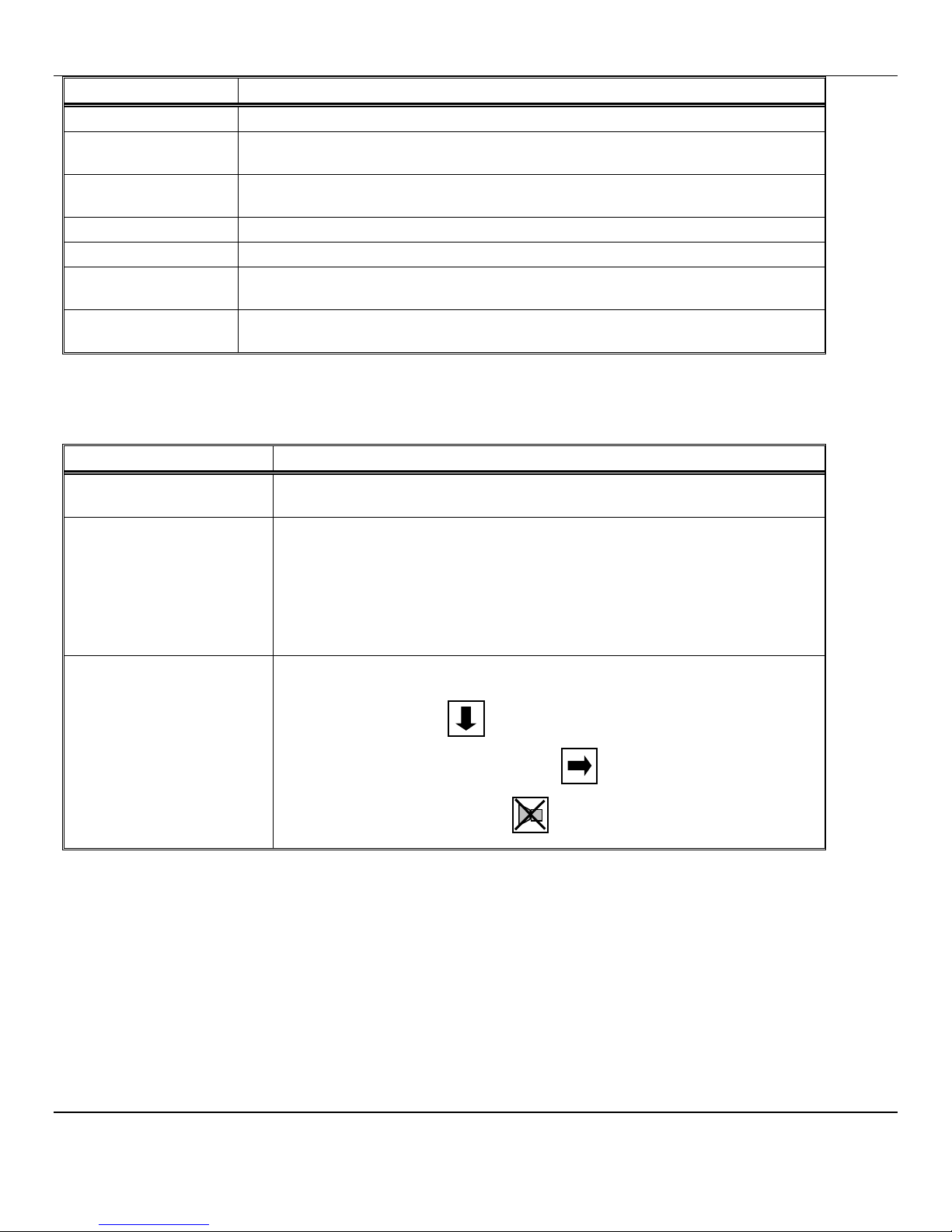
2.2 Display Panel Features
The display panel, shown in Figure 1, is viewed through the clear front cover of the enclosure, and is accessed by opening the
cover. Features are as follows:
Feature Description
Display
A 2 line, 16 character per line, LCD with backlight.
The numerical values of gas concentrations, and other information are displayed.
Visual
Alarms & Indicators On either sides of the display:
A red alarm LED for each sensor installed in the instrument, Low level alarm.
The top center of the panel:
A red alarm LED for all sensors installed in the instrument, High level alarm.
Near the center of the panel:
A green power indicator LED
A red fault alarm indicator LED
Pushbutton Switches
There are three of these, located near the center of the panel; they are yellow
rectangular membrane switches. They are:
•OPTION Switch The top left switch.
•SELECT Switch Directly to the right of the OPTION switch.
•AUDIO DEFEAT /
ALARM ACKNOWLEDGE
Switch
Directly below the OPTION switch.

ISA-300RAL ENMET Corporation
3
Figure 1: Features of ISA-300RAL
External
*
NOTE: Typical gas reading & alarm locations, depending on instrument configuration,
alarms & readings may be in alternate locations
5ft, Supplied with Monitor
Figure 1A: Regulator and Sample Air Hose
N
OTE
:
Typical facility air line pressures range from about 55 to 125 PSI. The outlet
pressure of the regulator supplied with the monitor, which is connected to
the inlet of ISA-300RAL the, should be set at 55 PSI,±5PSI.
Female Quick Release
to Inlet Port to ISA-300RAL
¼” NPT
O
2
%
CO
ppm
Front Cover Latch
Male Quick Release Fitting
Input Port
Sample/Calibration
See note below
Audio Alarm
Fault LED
SELECT
Switch
Power LED
OPTION
Swit
ch
A
LARM
A
CKNOWLEDGE
/
A
LARM
D
EFEAT
Switch
*Visual Alarm O
2
(If Oxygen option is installed)
See *note below
*Visual Alarm CO
(See *note below)
Mounting Flanges
2 places
CO2
ppm
Display,
see *note below
CO reading O
2
reading
CO
2
reading
Channel #1 Channel #3
Channel #2 Channel #4
Visual Alarm 2
ALARM 2
*Visual Alarm CO
2
(See *note below)
ISA-300RAL ENMET Corporation
4
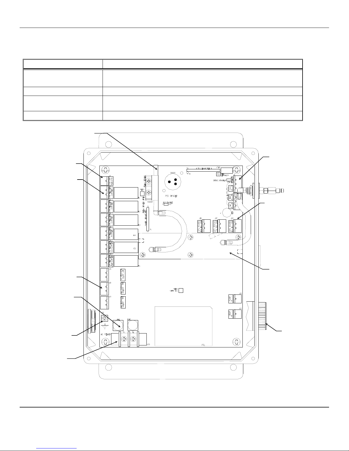
2.3 Circuit Board Features
The Display Panel is hinged on the left and is released by unscrewing the 2 screws located in the right corners. After releasing
the panel, it is swung to the left, exposing the interior of the enclosure. The Circuit Board is mounted at the back surface of the
enclosure interior. Features are shown in Figure 2.
Feature Description
Relay Terminals This group of terminals is located at the left side of the Circuit Board.
For the contacts for each of four alarm relays, and for the contacts of a fault relay.
Output Terminals One 4-20mA output per active channel. 2 channels/outputs per connector.
Sensor Manifold The sample manifold, the carbon monoxide, carbon dioxide and oxygen sensors are
located under this housing.
Figure 2:
ISA
-
300RAL
Interior Features
Flow Sensor
Power Input
Terminal J23
Audio
Alarm
Relay Terminals
(6 places)
Aux Terminals
Optional (2 places)
Horn Terminal
Fuse Holders
0.630 Amp
(2 places)
Ground Screw
J21
Sensor
Manifold
Digital Communication
Terminals
4
–
20mA Output
Terminals
4 places

ISA-300RAL ENMET Corporation
5
3.0 Installation
3.1 Mounting of Instrument
The ISA-300RAL should be located near the pipe or tank containing the air to be monitored, and upstream from where the air
is being used. The ISA-300RAL must be installed such that it samples the compressed air before it reaches the users.
Mount the instrument on an appropriate vertical surface using the mounting flanges provided. Avoid areas with excessive
vibration. The holes in the flanges are 0.31 inch in diameter and form a 6 x 10.75 inch rectangle.
See Figure 3.
It is recommended to use #8 drywall anchors and screws for mounting the ISA-300RAL to a drywall/sheetrock surface.
Dimensions are in inches.
Figure 3: ISA-300RAL
Mounting Dimensions
Mounting Holes
0.31” dia. 4 places
ISA-300RAL ENMET Corporation
6
3.2 Sample Air Supply
Tap the pipe or tank containing the breathing air and use appropriate fittings to connect the supplied regulator. The regulator must
be set to 55 PSIG.The instrument is designed to operate from an air supply pressure of 55 PSIG (±5PSI).
The sample air exits the instrument from the hole plug located on the bottom of the enclosure. Take care not to obstruct this
exit port.
3.3 Power Supply
The input power can vary from 100 to 240VAC, 50/60 Hz. Mains power should be connected to the Power Input Terminal J23
and the ground screw J21. See Figure 2 for location.
W
ARNING
:
Continuous gas detection and alarm systems become inoperative upon loss of primary power.
Upon supplying air and power to the instrument:
The green power on LED is lit.
The display backlight is lit, and instrument will step through a start-up sequence: unit serial number, software revision and
gases monitored may be shown on the display.
The instrument may go into alarm briefly, but the sensors stabilize quickly. If the instrument persists in alarm, acknowledge the
alarm by pressing the AUDIO DEFEAT /ALARM ACKNOWLEDGE switch. If alarm persists longer than 30 minutes, call ENMET
customer service personnel.
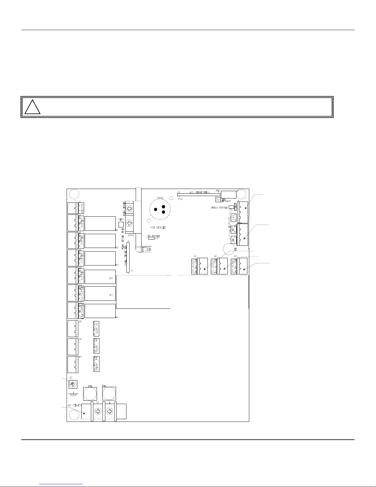
3.4 Outputs
Two types of alarm outputs are available, relay contacts and 4-20mA outputs.
Figure 2A: Relay, Input and Output Terminals
Relay 1
Channel 1
Alarm 1
Relay 2
Channel 2
Alarm 1
Relay 3
Channel 3
Alarm 1
Relay 4
Channel 4
Alarm 1
Relay 5
Channel 1-4
Alarm 2
Relay 6
Ch 1-4 / System
Fault
Connector
4-20mA Input
Connector
4-20mA Input
Connector 2
Channel 3 & 4
4-20mA Output
Connector 1
Channel 1 & 2
4-20mA Output
Connector RS485
Connector RS232
Connector RS485
Ground Screw J21
Power Input
Terminal J23
!
ISA-300RAL ENMET Corporation
7
3.4.1 Relay Contacts
Relay contacts are available for each alarm; these are SPDT, rated at 10Amp at 110VAC, and may be latching or non-latching
as required by the application.
They are accessed on the terminals next to each relay see Figure 2 & 2A. The contact positions are noted on the circuit board
next to each terminal.
Relays may also be configured as failsafe or non-failsafe. The default alarm relay configuration is for latching mode, and
failsafe. They may be reconfigured in the maintenance menu. See section 5.3.5 & 5.3.6
The PC Board is labeled for the relays in their un-energized state. If the relay is configured for failsafe, then this is also the alarm
condition state. Non-failsafe configured relays in the alarm state, are the reverse of the PC board labeling. Note that the
Fault(FLT) relay cannot be set to operate in a Non-Failsafe mode. Please see the Table 1 below:
Table 1 : Relay Failsafe Settings
Position
Failsafe
-
Alarm
Non
-
Failsafe
-
Alarm
J5 Relay 1 - NO Normally Open Normally Closed
J5 Relay 1 - COM Common Common
J5 Relay 1 - NC Normally Closed Normally Open
J6 Relay 2 - NO Normally Open Normally Closed
J6 Relay 2 - COM Common Common
J6 Relay 2 - NC Normally Closed Normally Open
J8 Relay 3 - NO Normally Open Normally Closed
J8 Relay 3 - COM Common Common
J8 Relay 3 - NC Normally Closed Normally Open
J10 Relay 4 - NO Normally Open Normally Closed
J10 Relay 4 - COM Common Common
J10 Relay 4 - NC Normally Closed Normally Open
J14 Relay 5 - NO Normally Open Normally Closed
J14 Relay 5 - COM Common Common
J14 Relay 5 - NC Normally Closed Normally Open
J15 Relay 6/FLT - NO Normally Open N/A
J15 Relay 6/FLT - COM
Common N/A
J15 Relay 6/FLT - NC Normally Closed N/A
Relays can be linked to specific alarms. The table below shows the default relay links. They may be changed in the
maintenance menu if required. See Section 5.0.
Channel 1
Channel 2
Channel 3
Channel 4
Relay 1 Low Alarm
Relay 2 Low Alarm
Relay 3 Low Alarm
Relay 4 Low Alarm
Relay 5 High Alarm High Alarm High Alarm High Alarm
In addition, there is a fault relay, which changes state whenever the instrument is in a fault condition. The contact positions are
noted on the circuit board next to each terminal. See Figure 2A. The coil of this relay is energized when the instrument is in
the non-fault state; the contact conditions given on the circuit board next to the terminal, are for the non-energized state, which
is identical to the fault state.
These relay contacts can be used to operate auxiliary alarms or other functions. It is recommended that power for auxiliary
equipment be supplied from an independent power source, separate for the ISA-300RAL. Place a hole in the enclosure for a
wire exit, and use appropriate cable fittings. Be sure to note the location and depth of hardware inside the enclosure.
ISA-300RAL ENMET Corporation
8
3.4.2 Optional 4-20mA Outputs
Isolated 4-20 mA outputs are available for data logging or other purposes. An output is supplied for each sensor supplied in a
particular instrument, and can be added when a sensor is added in the field. These outputs are available on the Connector 1 for
channels 1 & 2 and Connector 2 for channels 3 & 4.
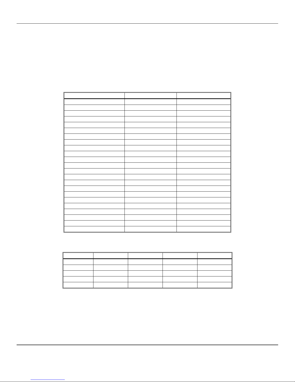
4mA corresponds to a sensor reading at the bottom of the instrument range and 20mA corresponds to a full scale reading.
Standard ranges are shown in Table 2.
Table 2: Sensor Output
Sensor 4mA 20mA
CO 0 50
O2 0 30
CO2 0 5000
Wiring requirements are the same as for the relays.
3.5 Installation Verification
All instruments are calibrated at the factory. You may, if a calibration kit is available, calibrate the CO, O
2
and CO
2
channels of
the instrument 24 hours after installation to verify proper installation and instrument operation. See Section 5.0, Maintenance,
for calibration instructions. Calibration is also recommended after the first month of operation. Subsequent calibrations should
be performed every 3 months.
ISA-300RAL ENMET Corporation
9
4.0 Operation
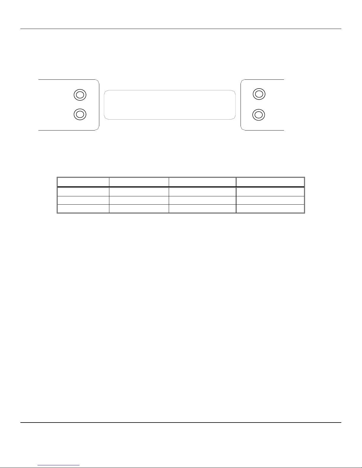
4.1 Normal Operation Condition
With the ISA-300RAL installed as described in section 3, and in clean air, the POWER green LED is on, the display is lit and
the information on the display is as shown in Figure 4 Display, for the sensor(s) installed in the
ISA-300RAL.The red alarm and fault LEDs are not lit.
Example of display with CO(ch 1), CO
2
(ch 2) and Oxygen(ch 3) options installed
Figure 4: ISA-300RAL
Operational Display
4.2 Alarm Set Points
There are two alarm set points for CO, CO
2
and oxygen. The factory settings of these alarm set points are shown in Table 3.
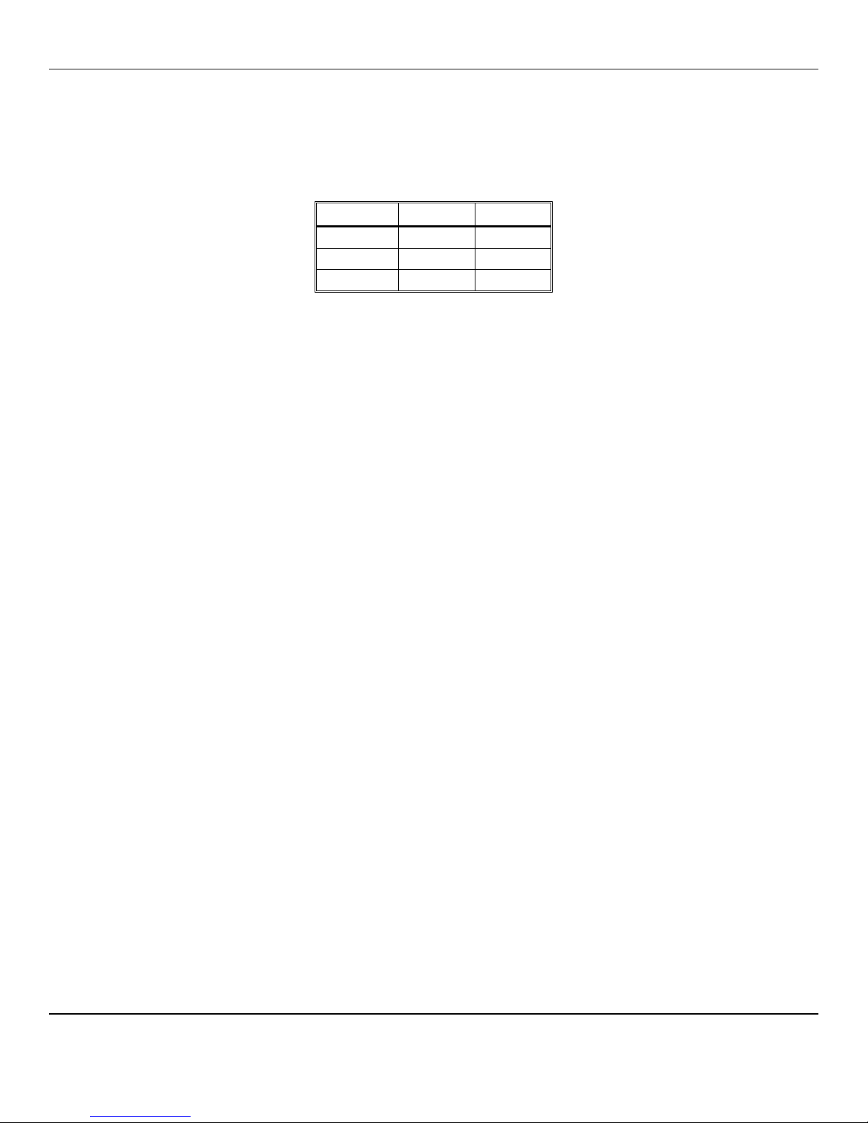
Table 3: Factory Alarm Set Points
Typical Channel #
Gas Alarm 1 Alarm 2
1 Carbon Monoxide 10 ppm 20 ppm
2 Oxygen Deficiency 19.5 % by volume 23.5 % by volume
3 Carbon Dioxide 500 ppm 1000 ppm
These alarm set points can be changed within limits; see the maintenance section of this manual for the procedure.
If the CO concentration increases above that of the alarm set point, the associated red LED is lit, the associated relay changes
state, and the audio alarm is activated.
If the oxygen content of the sample air decreases below the deficiency alarm set point, the associated red LED is lit, the
associated relay changes state, and the audio alarm is activated.
If the oxygen content of the sample air exceeds that of the abundance alarm set point, the associated red LED is lit, the audio
alarm is activated, and both the oxygen alarm relay and the oxygen high alarm relay change state.
The Alarm 1 differential value is the delay of the ISA-300RAL staying in alarm condition until after the measured reading
has returned past the alarm point by the differential value. Example: If the alarm set point is
Λ
10 and the differential is 2, the
ISA-300RAL will go into alarm at 10 and stay in alarm until the reading has dropped below 8.
CO
0
O2 20.9
CO2 300
CO
PPM
O
2
%
CO2
PPM

ISA-300RAL ENMET Corporation
10
4.3 Alarm Latching
An instrument is shipped with the alarms in the latching mode. The alarms may be independently configured in the non-
latching mode or differential setting by use of the maintenance menu.
See Section 5.3.3, for setting alarm 1 and alarm 2.
Standard Setting
IN THE LATCHING MODE: at the cessation of the condition which causes an alarm, the alarm indications do not cease, and the
alarm relay contacts do not revert to the non-alarm state, until the AUDIO DEFEAT /ALARM ACKNOWLEDGE switch is
pressed. An alarm can also be acknowledged by pressing the switch during the alarm condition; then at the cessation of the
alarm condition, alarm indications cease and alarm relays revert to the non-alarm state. After an alarm is acknowledged,
alarms in the latching configuration are re-armed to latch at the next alarm condition.
IN THE NON-LATCHING MODE:at the cessation of the condition that causes an alarm, the alarm indications automatically
cease, and the alarm relay contacts revert to the non-alarm state.
Differential Setting
The Alarm 1 differential value is the delay of the ISA-300RAL staying in alarm condition until after the measured reading
has returned past the alarm point by the differential value. Example: If the alarm point is
Λ
10 and the differential is 2, the
ISA-300RAL will go into alarm at 10 and stay in alarm until the reading has dropped below 8.
4.4 Audio Defeat
Pressing the AUDIO DEFEAT /ALARM ACKNOWLEDGE switch during an alarm temporarily silences the audio alarm. Relays and
alarm LEDs continue to function, in the alarm state, during an alarm condition. As long as the alarm condition persists, the
audio alarm will “chirp” every 20 seconds.
If after 15 minutes the alarm condition continues the audio alarm will reactivate at full intensity.
If any other alarm condition occurs while the audio alarm has been silenced it will force the audio alarm to reactivate
immediately.
4.5 Display
In clean air a display is shown in Figure 4.This position of the display is termed the "operational display". As explained
below, the display can be changed to furnish other information by using the OPTION and SELECT switches.
Concentrations of CO and CO2 are given in PPM (parts per million parts of air). Oxygen concentration is given in percent by
volume.
When sample flow is reduced below a limit, the bottom line of the display flashes “Low Flow Alarm”.
4.6 Fault Indications
4.6.1 Low Flow Indication
A flow sensor is used to furnish a low flow indication. When the sample air pressure drops below approximately 0.3 LPM, the
fault light and audio alarm are activated, and the display flashes “Low Flow Alarm”.
4.6.2 Other Fault Indications
Other fault indications are associated with sensor zero and calibration activities, and are described in the maintenance Section
5.0 of this manual.

ISA-300RAL ENMET Corporation
11
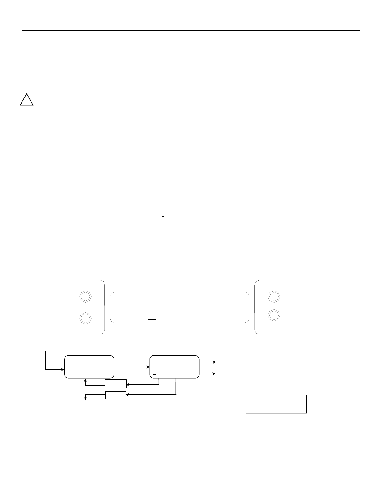
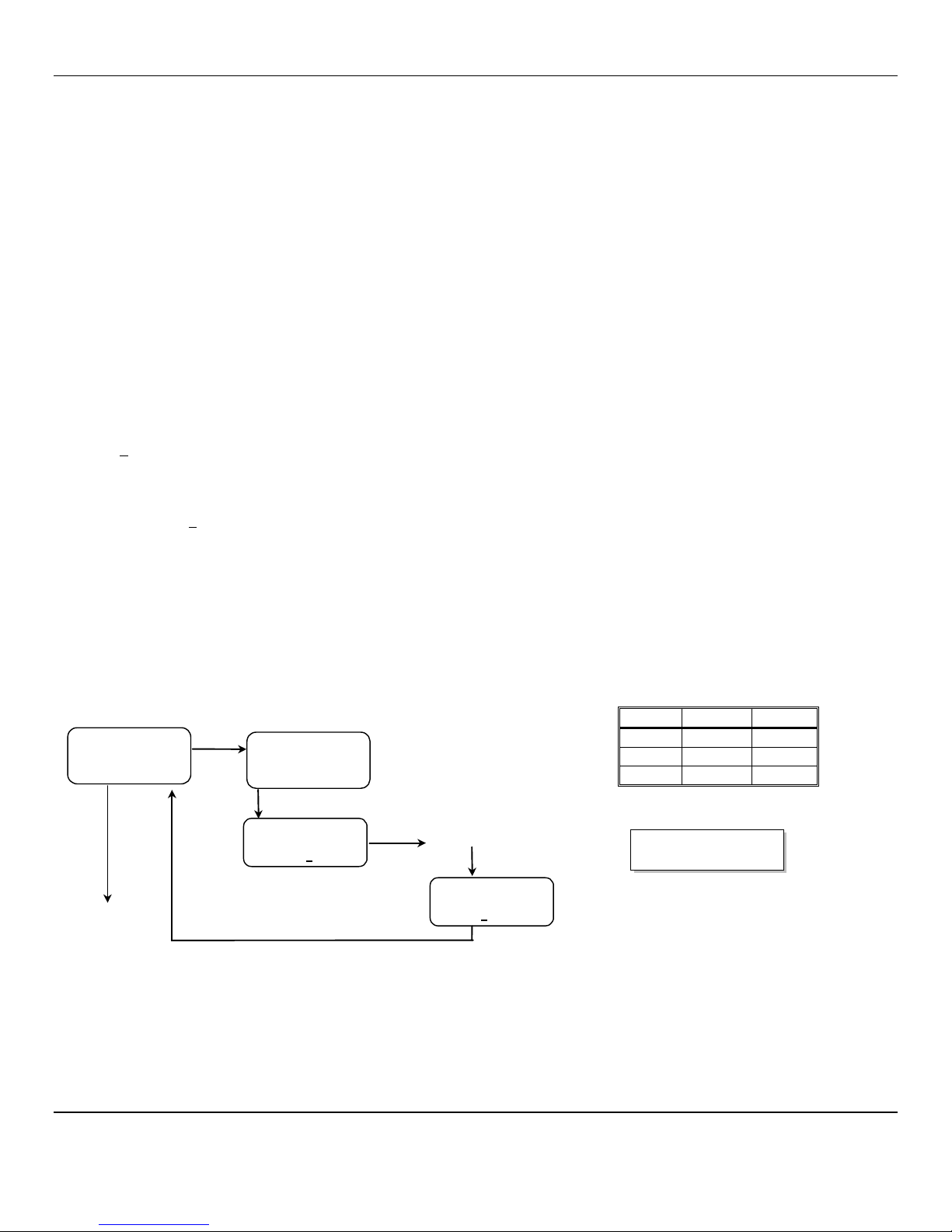
4.7 Operational Menu
The operational menu allows the user to:
View alarm set point concentration values
View alarm latching configurations
Enter the maintenance menu with the proper Password.
The operational menu is accessed with the OPTION and SELECT switches. The operational menu flow chart is shown in Figure
5,
Pressing the OPTION switch is indicated with a "O"
Pressing the SELECT switch is indicated with a "S".
If the instrument is left at any location in the operational or maintenance menus, other than the operational display, with no
action taken for a period of 45 seconds, it returns to the operational display.
Figure 5: ISA-300RAL
Operation Menu Flow Chart
O
= Press Option switch
S= Press Select switch
O
Λ
L10 A1 vL500
Vl19.5
Λ
D 500
O
No
Function
S
S
Λ
L20 A2
Λ
23.5
Λ
L23.5
Λ
1000
O
No
Function
O
S
CH-1 CH-3
CH-2 CH-4
No
Function
S
Enter Maint Menu Enter Password
_
See Maintenance Menu Diagram
S
S
S
O
O
O
O
S
for each active channel
CH1 SCALE (CO)
0 – 50
PPM
CH4 SCALE (CO2)
0 – 5000
PPM
CH3 SCALE
(O2)
0 0 – 30 0 %
CH4 SCALE (HC)
0 – 5000
PPM
Displays are
examples
of gases:
Channel 1 = Carbon Monoxide
Channel 2 = Oxygen
Channel 3 = Carbon Dioxide
Channel 4 = Hydrocarbons
6– Indicates relay is engaged
Displays are examples of Alarms
Λ
- Indicates alarm triggered on
increasing value of reading
v - Indicates alarm triggered on
decreasing value of reading
Displays are examples of Alarms
L– Indicates alarm is in latching
mode.
(no Lpresent) – Indicates alarm
is in non-latching mode.
Displays are examples of Alarms
D– Indicates alarm is in
Differential Setting.
(no Dpresent) – Indicates alarm
is in Standard Setting.
S
50 mASPAN 30.0
68 5000
O
No
Function
ALARM1 Del ys
(Seconds)
O
S
No
Function
5 5
5 5
Alternating
S
Rel ys 123456
6=ON
666666
O
No
Function
ISA-300RAL ENMET Corporation
12
5.0 Maintenance
The ISA-300RAL requires periodic sensor calibration and replacement. Calibration of toxic gas and oxygen sensor should be
performed immediately following installation, one month after installation and every 3 months thereafter. Oxygen and CO
sensor have an estimated lifetime of 1 – 3 years. The CO2 sensor has an estimated lifetime of 3 – 5 years. Sensors should be
replaced when they will not calibrate or shortly before the end of their estimated lifetime.
5.1 Cleaning Instructions
CAUTION:Never spray a cleaning solution on the surfaces of the ISA-300RAL devices.
Clean the exterior of the ISA-300RAL enclosures with a mild soap solution on a clean, damp cloth. Do not soak the cloth with
solution so that moisture drips onto, or lingers on, external surfaces.
Under no circumstances should organic solvents such as paint thinner be used to clean instrument surfaces.
5.2 Maintenance Menu
5.2.1 Accessing Maintenance Menu
The ISA-300RAL maintenance menu is accessed by entering the proper password with the OPTION and SELECT switches. See
Section 5.2.2 Figure 6 for full Maintenance Menu flow chart.
Entrance to the maintenance menu is guarded with a four-digit Password. The factory default setting of the password is 1270.
When a valid numerical password is inserted, the user is allowed to enter the maintenance menu.
To enter the maintenance menu. Press the OPTION switch until “Enter Maint Menu” is displayed then press SELECT switch for
the Enter Password menu. Enter the valid password as described below.
In the "Enter Maint Menu" position
Press the SELECT switch "Enter Password T0" is displayed. Press SELECT switch once, to move cursor to next digit,
this will be the first digit of the password.
In the T000 position, the underline cursor is under the left digit.
Press the OPTION switch to change the left digit; select the correct digit.
Press the SELECT switch, which locks the digit in place and moves the cursor one digit to the right.
Continue this process until the four-digit password is complete. When a valid password is inserted in this manner, the display is
transferred to the "Calibration" portion of the menu. If an invalid password is inserted you are returned to the Enter Maint
Menu display.
Example: Password Display (with factory installed password entered) and Flow Chart below.
To Calibration
See Section 5.2.2 Figure 6 for full Maintenance Menu flow chart.
Enter Password
1270
CO
PPM
O
2
%
O = Option Switch
S = Select Switch
CO2
PPM
O
S
S
Valid
Enter Password
T
0
Invalid
Enter
Maint Menu
Changes digit indicated by underscore cursor
Locks underscored digit and moves cursor to next digit
O
(6)
!
ISA-300RAL ENMET Corporation
13
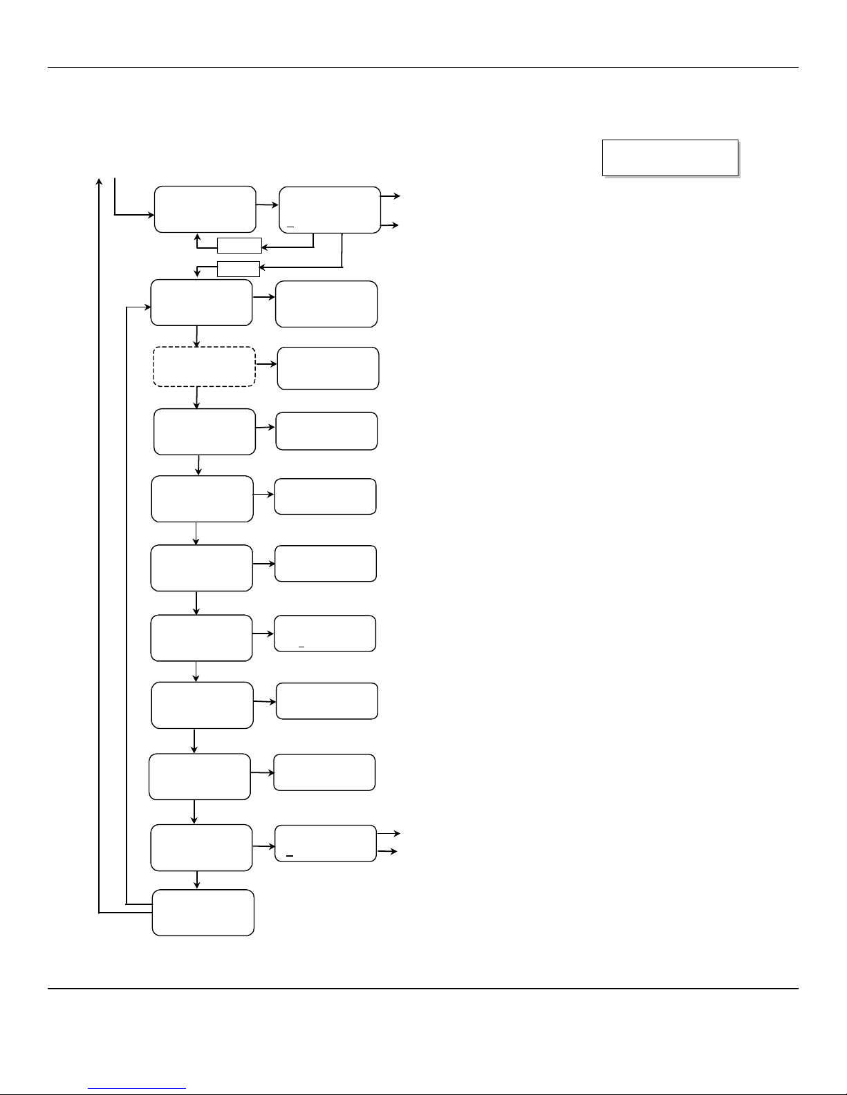
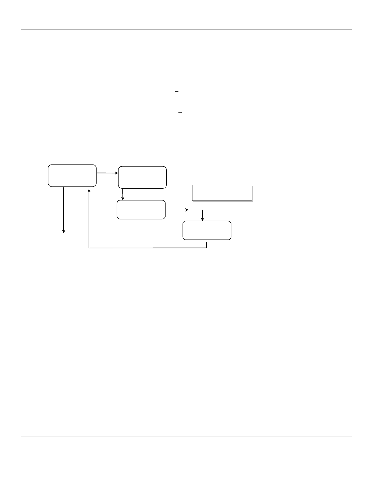
5.2.2 Maintenance Menu Flow Chart
The maintenance menu diagram is shown in Figure 6 Maintenance Menu Flow Chart. From the operational display, press
the OPTION switch 6 times or until; "Enter MAINTENANCE Menu" is displayed.
Figure 6: ISA-300RAL
Maintenance Menu Flow Chart.
O = Press Option
S= Press Select
O
S
MAINTENANCE MENU
Exit maint menu
Press
O
PTION
to return to top of maintenance menu.
Press
S
ELECT
to return to operational menu.
See Section
5.3.9 for instructions on how to exit Maintenance Menus.
To/From
Operational
Display
From Operational Menu
Press O
PTION
(6 times)
S
Enter Maint Menu
O
S
Enter Password
0000
Changes digit indicated by underscore cursor
Locks underscored digit and moves cursor to next digit
O
(6)
Valid
Invalid
O
S
MAINTENANCE MENU
Set New Password
Password
XXXX
O
S
Changes digit indicated by underscore cursor
Locks underscored digit and moves cursor to next digit
See Section 5.3.8 for changing password instructions.
O
S
Calibration
Select (Gas)
MAINTENANCE MENU
Calibration
Press
O
PTION
until the channel to be Calibrated is displayed
See Section
5.3 for calibration instructions.
O
S
MAINTENANCE MENU
Set Alarm1
Alarm
1
Select: XX
Press
O
PTION
until the gas alarm to be Set is displayed
See Section
5.3.3 for setting alarms instructions.
O
S
Alarm
Select: XX
MAINTENANCE MENU
Set Alarm
Press
O
PTION
until the gas alarm to be Set is displayed
See Section
5.3.3 for setting alarms instructions.
O
S
MAINTENANCE MENU
Set Alarm Delays
Alarm Delay
Select: XX
Press
O
PTION
until the gas alarm delay to be
Set
is displayed
See Section
5.3.4 for setting alarms instructions.
O
S
MAINTENANCE MENU
Configure Alarms
Ch 1, , 3, 4
R1 L
Pressing
O
PTION
changes letter indicated by underscore cursor
See Section
5.3.5 for configuring relay instructions.
O
S
MAINTENANCE MENU
Relay Failsafes
Relay Failsafes
R:1 Failsafe ON
Pressing
O
PTION
changes Failsafe setting from ON to OFF
See Section
5.3.6 for configuring relay failsafe instructions.
MAINTENANCE MENU
Scale mA Xmtrs
Press
O
PTION
until gas to be Set-Up is displayed
See Section 5.3.2 for transmitter set-up instructions.
If installed
Scale mA Xmtrs
Select (Gas)
O
S
O
S
MAINTENANCE MENU
mA Output Span
mA Output Span
Select: (Gas)
Press
O
PTION
until the gas span to be Set is displayed
See Section
5.3.7 for output span instructions.
ISA-300RAL ENMET Corporation
14
5.3 Calibration for CO, O
2
and CO
2
Calibration is the process of setting the instrument up to read accurately when exposed to a target gas. This is a two step
process. A Low Calibration sets clean air reference point and the High Calibration function sets the sensitivity of the
instrument.
Calibration equipment is available from ENMET Corporation to calibrate the ISA-300RAL. A list of needed material is in
Section 7.0. A calibration adapter will have a fitting for the gas cylinder on one side, and a quick-disconnect to attach to the
instrument on the other.
You may exit the calibration section, at any time, by pressing and holding the OPTION switch for 3 seconds, if entering
calibration section by mistake or calibration gas is not available.
Wait 24 hours after initially supplying air and power to the ISA-300RAL sensor before initial calibration. It is not necessary to
open the Front Panel to make adjustment. The calibration functions are operated through the OPTION and SELECT switches on
the front panel.
After entering a valid password to maintenance menu, see Section 5.2.1, the calibration section is the first menu section; enter
by pressing the SELECT switch.
Supply sensor with clean air for LowCal/ZeroCal setting and apply calibration gas for HiCal/SpanGas setting.
Press the SELECT switch "Calibration Select XX" is displayed. XX = the gas to be calibrated
Press the OPTION switch, if needed, to change to the gas to be calibrated.
Press the SELECT switch, the gas & current reading are displayed in upper portion of display. The mV reading & "LowCal
0" is displayed in the lower portion of display. This is the LowCal setting, usually zero, clean air must be supplied to the
sensor. This reading needs to be at or near zero. If it is not then a cylinder of clean 20.9 air should be used. See Figure 7 if
this is required.
Press the SELECT switch, that moves the cursor one digit to the right when the last digit is accepted the display will move
to "HiCal xx" gas calibration. xx = the level of gas to be used for calibration. The mV reading is shown in the upper right
hand corner of the display.
Apply calibration gas to sensor. See Figure 7. After about 1 minute and mV reading has stabilized.
Press the SELECT switch, that moves the cursor one digit to the right, when the last digit is accepted and the calibration is
successful the display will momentarily show Cal OK then slope and off set readings, before returning to the Calibration
Menu
Repeat above steps for each channel to be calibrated.
To continue on too next section Press the OPTION switch.
Example: Full Calibration Flow Chart, for CO
From Valid Password Entry
O
S
S
Calibration
Select (Gas)
MAINTENANCE MENU
Calibration
OPress O
PTION
until the gas to be
Calibrated is displayed
CO:
XX
11
LowCal:
0
000
S
each digit
CO:
XX
14
HiCal:
0
000
S
each digit
Default Calibration Points
Gas LowCal HiCal
CO 0 20
O2 N/A 20.9
CO2 0 1000
O = Press Option
S= Press Select

ISA-300RAL ENMET Corporation
15
Figure 7: Connection of Calibration Gas Cylinder
5.3.1ALow Cal/ZeroCal Adjust
A Low Cal function should be performed only when the ISA-300RAL sensor are exposed to clean uncontaminated air. Use a
cylinder of 20.9% oxygen to provide a clean air reference if necessary. Attach the cylinder to the calibration adapter, attach the
adapter to the instrument and allow gas to flow over the sensor for up to 4 minutes.
Enter the maintenance menu by repeatedly pressing OPTION switch, until the maintenance menu is displayed. See Figure 6,
ISA-300RAL Maintenance Menu flow chart.
The first menu available is the Low Cal/ZeroCal.
Press the SELECT switch 4 times to perform a Low Cal.
If the Low Cal/ZeroCal is successful, The display will change to Hi Cal/SpanGas.
If you wish to Hi Cal/SpanGas the sensor apply calibration gas. Proceed to gas calibration Section 5.3.1B
If you wish to Exit the maintenance menu, Press and hold OPTION switch until the Maintenance Menu is displayed then
release. Then press OPTION switch until “Exit maint menu” appears and then press SELECT switch to return the instrument to
the Operational Display
If the Low Cal/ZeroCal is Not successful, sensor is outside of safe parameters to Low Cal, a “SLP/Off Set err” will be
indicated. Repeat Section 5.3.1 Low Cal/ZeroCal Adjust making sure to use a cylinder of 20.9% Oxygen.
5.3.1BHigh Cal/SpanGas Adjust
A High Cal/Span Gas should only be preformed after a successful Low Cal/ZeroCal has been completed.
Press the SELECT switch, that moves the cursor one digit to the right when the last digit is accepted the display will move
to "HiCal xx" gas calibration. xx = the level of gas to be used for calibration. The mV reading is shown in the upper right
hand corner of the display.
Apply calibration gas to sensor. See Figure 7. After about 1 minute and mV reading has stabilized.
Press the SELECT switch, that moves the cursor one digit to the right, when the last digit is accepted and the calibration is
successful the display will momentarily show Cal OK then slope and off set readings, before returning to the Calibration
Menu
Repeat above steps for each channel to be calibrated.
To continue on too next section Press the OPTION switch.
Cylinder of Gas
Cylinder Valve
and Regulator
Calibr
ation/Sample
Port
ISA-300RAL ENMET Corporation
16
5.3.2 Set 4 –20mA Transmitter Scale
This section of the maintenance menu is installed when there are 4-20mA style sensors for other gases. This function is
normally performed at the factory and is not usually required to be performed in the field unless a new transmitter is installed.
After entering a valid password into maintenance menu, the Scale mA Xmtrs section is the second menu section, if it is
installed, enter by pressing the SELECT switch
Press the SELECT switch "mA Xmter Scale: Select XX" is displayed. XX = the gas to be set up.
Press the OPTION switch, if needed, to change to the gas to be set up.
Press the SELECT switch, “Ch#: mAXmter: 4mA: 0000” is displayed
Press the SELECT switch, that moves the cursor one digit to the right when the last digit is accepted the display move to the
full Scale mA Xmtrs menu
Press the SELECT switch, “Ch#: mAXmter: 20mA: 0000” is displayed
Press the SELECT switch, that moves the cursor one digit to the right when the last digit is accepted the display will return
to the Scale mA Xmtrs menu
Repeat these steps for each 4 –20mA transmitter.
Press the OPTION switch, to continue on to the next section of the Maintenance Menu.
Example: Sensor/Transmitter Set Up Flow Chart
O
S
S
mA
Xmtr Scale
Select (Gas)
MAINTENANCE MENU
Scale
mA
Xmtrs
OPress O
PTION
until the gas to be
Set Up
is displayed
CH#:
XX
mA
Xmter
4mA:
0
000
S
each digit
CH#:
XX
mA
Xmter
20mA:
0
000
S
each digit
O = Press Option
S= Press Select

ISA-300RAL ENMET Corporation
17
5.3.3 Set Alarm Points
Factory alarm set points are discussed in Section 4.2, See Table 3. To change the alarm points, you must enter the maintenance
menu.
Entrance to the maintenance menu is guarded with a four-digit Password. The factory default setting of the password is 1270.
When a valid numerical password is inserted, the user is allowed to enter the maintenance menu.
In the "Enter Maint Menu" position
Press the SELECT switch "Enter Password T0" is displayed. Press SELECT switch once, to move cursor to next digit, this
will be the first digit of the password.
In the T000 position, the underline cursor is under the left digit.
Press the OPTION switch to change the left digit; select the correct digit.
Press the SELECT switch, which locks the digit in place and moves the cursor one digit to the right.
Continue this process until the four-digit password is complete. When a valid password is inserted in this manner, the display is
transferred to the "Calibration" portion of the menu. If an invalid password is inserted you are returned to the Enter Maint
Menu display.
After entering a valid password:
Press the OPTION switch until; “Maintenance Menu Set Alarm1” appears on display.
Press the SELECT switch, "ALARM1 Select: XX" is displayed. XX = the gas of alarm point to be changed.
Press the OPTION switch until, desired gas is displayed.
Press the SELECT switch; "ALARM 1
V
" is displayed, with the flashing placeholder underscore cursor, under the left most
character,
Λ
for
ascending trigger point or
V
for descending trigger point indicator.
Press the OPTION switch to toggle between
Λ
and
V
; select the correct indicator.
Press the SELECT switch to lock in the correct indicator. "ALARM 1
STD
" is displayed
Press the OPTION switch to toggle between STD and
DIFF; select the correct indicator.
Press the SELECT switch to lock in the correct indicator.
If STD is selected, "ALARM 1
V
L" is displayed, to set alarm 1 value.
The next character is the latching indicator Lor NOLpress the OPTION switch to toggle the latching mode.
The next character is the negative sign –press the OPTION switch to toggle the negative sign.
The next characters are the alarm 1 value, press the OPTION switch to select each digit of the value
When the last digit is accepted display returns to the "Set Alarm1" position.
If DIFF is selected, "ALARM 1
Λ DIFF 000
" is displayed, to set alarm 1 differential.
The next characters are the alarm 1 value, press the OPTION switch to select each digit of the value
Press the SELECT switch to lock in the correct character and move the cursor to the right.
"ALARM 1
DIFF BAND 000
" is displayed, press the OPTION switch to select each digit of the value.
The next characters are the alarm 1 differential value, press the OPTION switch to select each digit of the value
Press the SELECT switch to lock in the correct character and move the cursor to the right.
When the last digit is accepted display returns to the "Set Alarm1" position.
Note: The Alarm 1 differential value is the delay of the ISA-300RAL staying in alarm condition until after the measured
reading has returned past the alarm point by the differential value. Example: If the alarm set point is
Λ
10 and the differential
is 2, the ISA-300RAL will go into alarm at 10 and stay in alarm until the reading has dropped below 8.
Repeat for each sensor alarm 1 to be changed.
Press the OPTION switch to move to alarm 2, "Set ALARM2" is displayed.
Repeat as for alarm 1 using the STD section.
Press OPTION switch until “Exit maint menu” appears, then press SELECT switch to return the instrument to the Operational
Display
Other manuals for ISA-300RAL
1
This manual suits for next models
1
Table of contents
Other ENMET Monitor manuals


