ENMET AM-5175 User manual

ENMET Corporation
PO Box 979
Ann Arbor, MI 48106-0979
www.enmet.com
Manual part number
80003-551
MCN-14-003, 03/20/14
AM-5175
Ambient Air Monitor
Manual

Table of Contents
1.0 Introduction..............................................................................................................................................................1
1.1 Unpack.................................................................................................................................................................1
1.2 Check Order.........................................................................................................................................................1
1.3 Serial Numbers.....................................................................................................................................................1
2.0 Components of the AM-5175..................................................................................................................................2
2.1 AM-5175 elements...............................................................................................................................................2
2.2 AM-5175 Operational Features............................................................................................................................2
2.3 Circuit Board Features.........................................................................................................................................3
3.0 Installation of the AM-5175....................................................................................................................................4
3.1 Mounting AM-5175.............................................................................................................................................4
3.1.1 Wiring the AM-5175.....................................................................................................................................5
3.1.2 Power Supply................................................................................................................................................5
3.3 Relay Contacts.....................................................................................................................................................6
4.0 Operation .................................................................................................................................................................7
4.1 Start Up AM-5175 ...............................................................................................................................................7
4.1.1 Typical Start Up............................................................................................................................................7
4.2 Normal Display Mode..........................................................................................................................................8
4.2.1 Alarm Conditions AM-5175.........................................................................................................................8
5.0 Maintenance.............................................................................................................................................................9
5.1 Maintenance Menus.............................................................................................................................................9
5.2 Calibration of the AM-5175...............................................................................................................................11
5.2.1 Exit Maintenance Menu..............................................................................................................................12
5.2.2 Zero Adjust .................................................................................................................................................12
5.2.3 Gas Span .....................................................................................................................................................13
5.2.4 Alarm Set Points .........................................................................................................................................14
5.2.5 mA Span Set ...............................................................................................................................................14
5.3 Sensor Replacement...........................................................................................................................................15
5.3.1 A Factory calibration must be performed. ..................................................................................................15
6.0 Accessory and Replacement Parts .........................................................................................................................16
7.0 Technical Data and Specifications.........................................................................................................................16
8.0 WARRANTY ........................................................................................................................................................17
List of Tables
Table 1 : Relay Failsafe Settings....................................................................................................................................6
Table 2: AM-5175 Maintenance Menus Sequence........................................................................................................9
List of Illustrations
Figure 1: External AM-5175 Features ...........................................................................................................................2
Figure 2: AM-5175 Circuit Board Features...................................................................................................................3
Figure 3: Mounting AM-5175........................................................................................................................................4
Figure 4: Power Terminal Connections AM-5175.........................................................................................................5
Figure 5: Relay Terminal Connections AM-5175..........................................................................................................6
Figure 6: AM-5175 Maintenance Menu Flow Chart....................................................................................................10
Figure 7: Calibration Adapter......................................................................................................................................11
Figure 8: AM-5175 Sensor Replacement.....................................................................................................................15
Reference Information:
NOTE:[important information about use of instrument]
CAUTION:[affects equipment – if not followed may cause damage to instrument, sensor etc…]
W
ARNING
:
[affects personnel safety – if not followed may cause bodily injury or death.]
Earth Ground

AM-5175 ENMET Corporation
1
1.0 Introduction
The AM-5175 is an ambient air monitoring instrument that measures and detects gases utilizing electrochemical sensor. The
AM-5175 is NOT in an enclosure rated for use in a Class I, Div 1, Groups B, C, D classified area and can not be installed in a
hazardous location.
Features of the AM-5175:
continuous monitoring of the ambient air
continuous LCD display of gas and vapor concentrations
menu driven operational and maintenance controls
menu driven calibration procedure
audio and visual alarms indicate unsafe conditions
alarm relay contacts available on terminals
a fault relay and visual fault alarm
alarm acknowledgement capability including audio defeat
mA outputs for target gas
N
OTE
:All specifications stated in this manual may change without notice.
1.1 Unpack
Unpack the AM-5175 and examine it for shipping damage. If such damage is observed, notify both ENMET customer service
personnel and the commercial carrier involved immediately.
Regarding Damaged Shipments
N
OTE
:It is your responsibility to follow these instructions. If they are not followed, the carrier will not honor
any claims for damage.
This shipment was carefully inspected, verified and properly packaged at our company and delivered to the carrier in
good condition.
When it was picked up by the carrier at ENMET, it legally became your company’s property.
If your shipment arrives damaged:
•Keep the items, packing material, and carton “As Is.” Within 5 days of receipt, notify the carrier’s local office and
request immediate inspection of the carton and the contents.
•After the inspection and after you have received written acknowledgment of the damage from the carrier, contact
ENMET Customer Service for return authorization and further instructions. Have your Purchase Order and Sales
Order numbers available.
ENMET either repairs or replaces damaged equipment and invoices the carrier to the extent of the liability coverage,
usually $100.00. Repair or replacement charges above that value are your company’s responsibility.
The shipping company may offer optional insurance coverage. ENMET only insures shipments with the shipping
company when asked to do so in writing by our customer. If you need your shipments insured, please forward a written
request to ENMET Customer Service.
Regarding Shortages
If there are any shortages or questions regarding this shipment, please notify ENMET Customer Service within 5 days of
receipt at the following address:
ENMET Corporation
680 Fairfield Court
Ann Arbor, MI 48108
734-761-1270 734-761-3220 Fax
1.2 Check Order
Check, the contents of the shipment against the purchase order. Verify that the AM-5175 is received as ordered. Each AM-
5175 is labeled with its target gas. If there are accessories on the order, ascertain that they are present. Check the contents of
calibration kits. Notify ENMET customer service personnel of any discrepancy immediately.
1.3 Serial Numbers
Each AM-5175 is serialized. These numbers are on tags on the equipment and are on record in an ENMET database.
AM-5175 ENMET Corporation
2
2.0 Components of the AM-5175
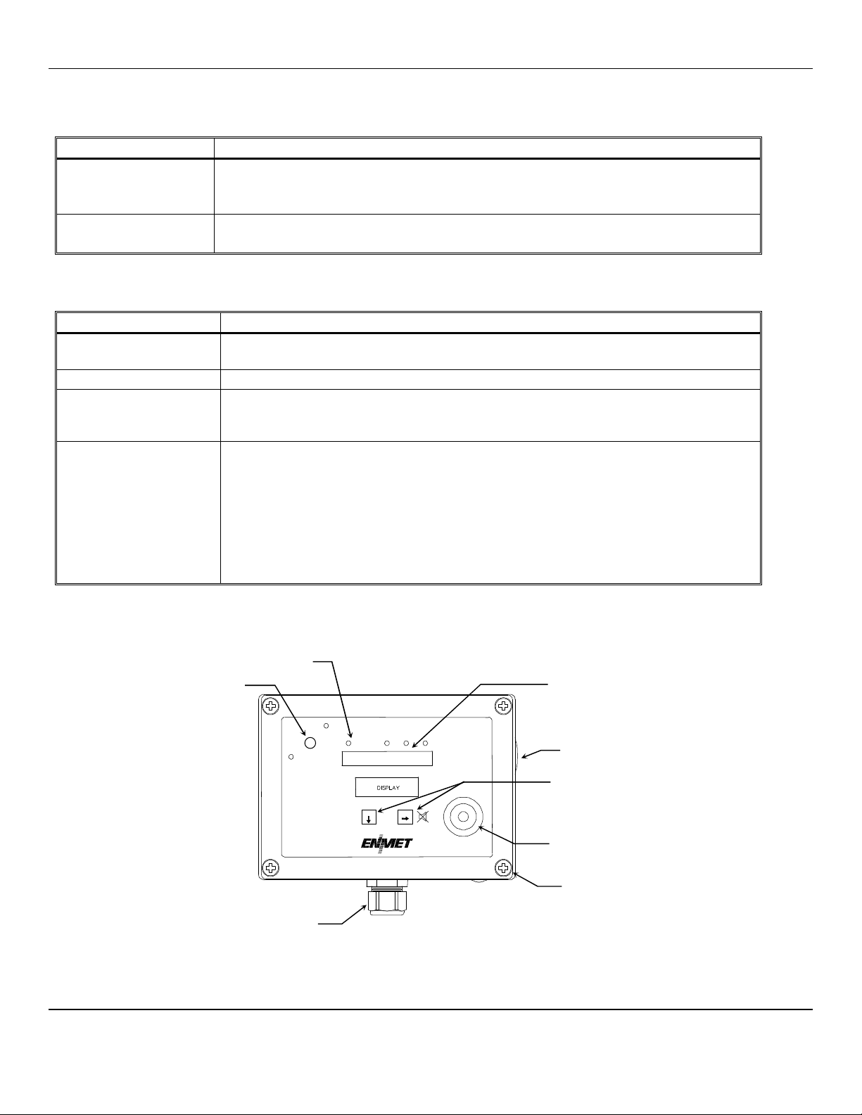
2.1 AM-5175 elements
See Figure 1 for location of elements:
Feature Description
Enclosure A polycarbonate box, approximately 7 x 5 x 3, with a detachable front cover.
4 holes for mounting the enclosure to a vertical surface. Located at the corners of the bottom
of the enclosure, directly beneath the 4 front cover retaining screws. See Figure 3
Front Cover Detachable front cover of AM-5175 with Display Panel. See Section 2.2 and Figure 1
There are 4 Screws that hold the front cover in place.
2.2 AM-5175 Operational Features
The Display Panel is attached by a cable and is released by unscrewing the 4 screws located in the corners. After releasing the
panel, it is swung upward, exposing the interior of the enclosure. See Figure 1 for location of features.
Feature Description
Display A single line, 8 character LCD with backlight. Indicates the level of gas detected by sensor.
The numerical value of gas concentration and other information is displayed.
Audio Alarm(Horn) Audio alarm (105 dB at 30cm/12in). The audio alarm is activated when the unit is in alarm.
Visual:
Indicators and Alarms LED indicators:
Power / Fault Indicator LED, Green / Red
Alarm (3) Indicator LED, Red
Membrane Switches 2 Pushbutton Switches on front panel
control the instrument maintenance functions. The
pushbutton switch locations are indicated by:
MENU ↓: Advances the instrument display through operation information and maintenance
menus
SELECT: Disables audio alarm temporally and
Selects the maintenance menu operations such as, Zero, Span, Exit menu or sets
proper calibration values for Zero or Span
See Section 4.0 and 5.0 for operational and maintenance flow charts.
Three alarm points are preprogrammed into the AM-5175. At each alarm point, an LED on the front panel is activated. There
are 4, 10 Amp relay contacts at each alarm point, plus a fault relay. See Section 3.2 for wiring information.
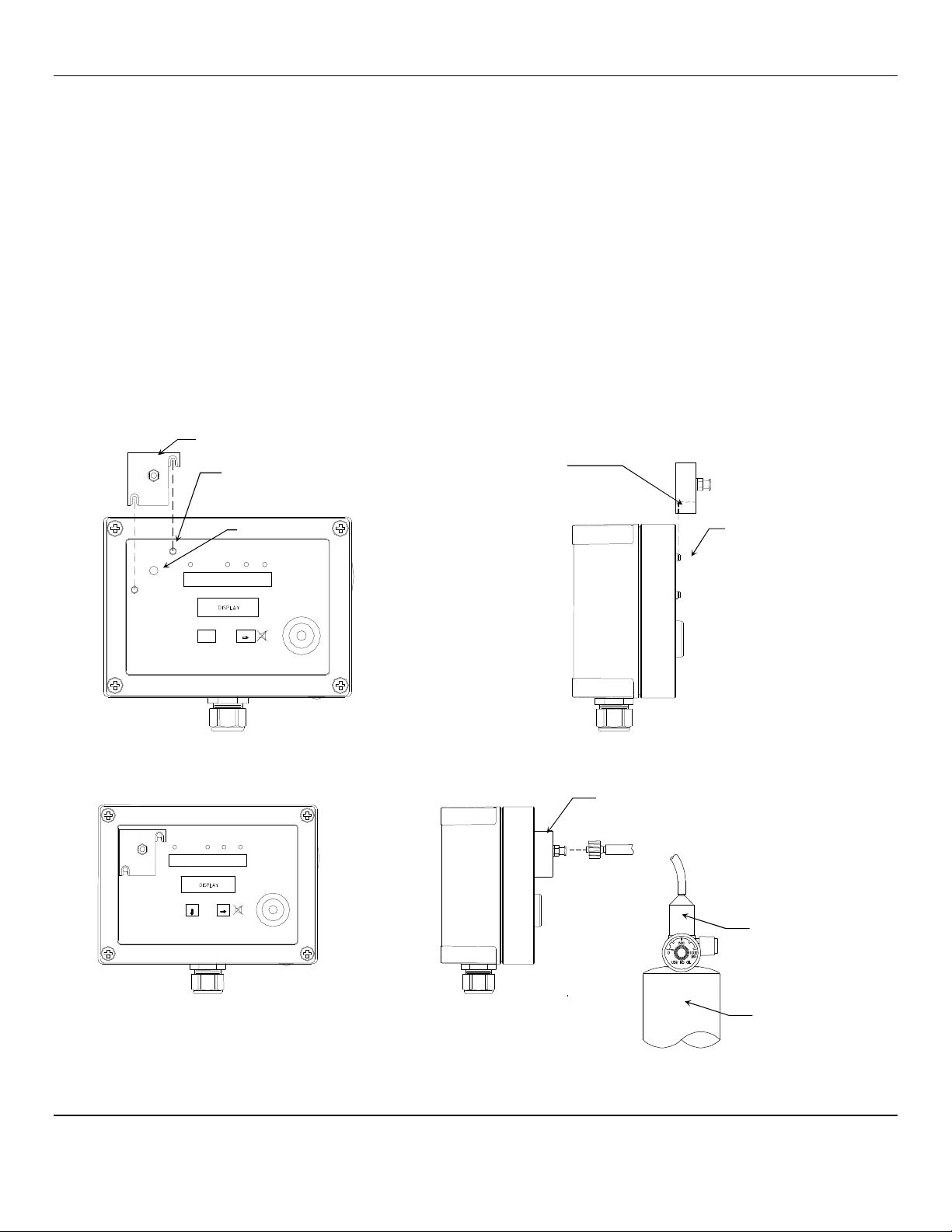
Figure 1: External AM-5175 Features
Menu
Select
Audio Alarm
Power Wiring
Strain Relief
Visual Indicators:
Alarm1, Alarm2, Alarm3
Pushbutton/Membrane
Switches
Visual Indicator
Power/Fault
Front Cover
Retaining Screws
4 places
Remote Wiring Access
Sensor
AM-5175 ENMET Corporation
3
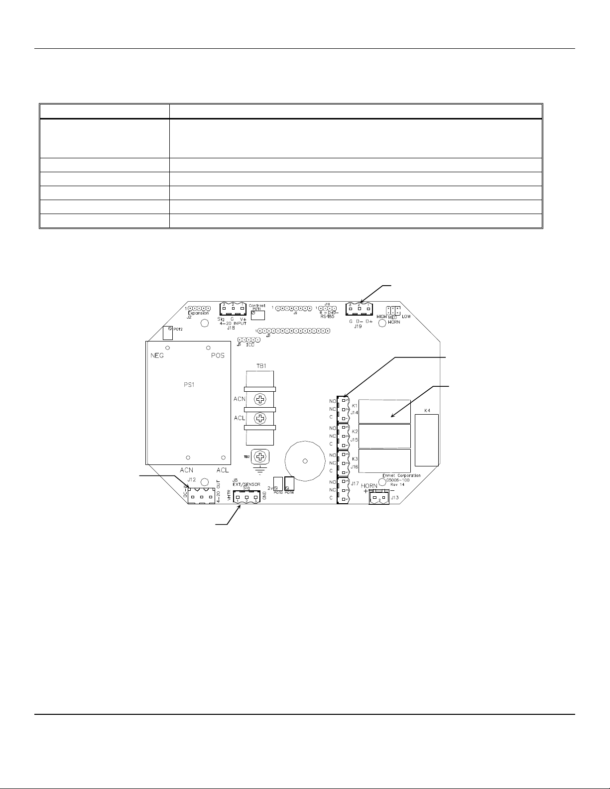
2.3 Circuit Board Features
The Display Panel is attached by a cable and is released by unscrewing the 4 screws located in the corners. After releasing the
panel, it is swung upward, exposing the interior of the enclosure. The Circuit Board is mounted at the back surface of the
enclosure interior. Features are shown in Figure 2.
Feature Description
Relay Terminals:
J14, J15, J16, J17 This group of terminals is located on the Circuit Board.
For the contacts for each of three alarm relays, and for the contacts of a fault relay.
See Section 3.3
Terminal J12 For VDC back-up power in and the 4-20 mA output. See Section 3.1.2
Sensor Terminal J8 Sensor connection, See Section 3.2
Data Terminal J19 RS-485 input/output
Potentiometer 2, 3 & 4 Not used in AM-5175 Do Not Adjust
Figure 2: AM-5175 Circuit Board Features
Relay Terminals
J14, J15, J16, J17
Relays
K1, K2, K3, K4
Terminal J12
DC Power In
4
-
20mA Output
RS
-
485 Input/Output
Terminal J19
Sensor Connection
Terminal J8

AM-5175 ENMET Corporation
4
3.0 Installation of the AM-5175
The AM-5175 is supplied with a strain relief and a standard U.S. 3 prong power line cord.
NOTE:This control panel is NOT rated for hazardous locations. The control panel must be located in a NON-Hazardous area.
3.1 Mounting AM-5175
Mount the AM-5175 instrument on an appropriate vertical surface, leaving room for lid to be opened, using the mounting holes
provided. Avoid areas with excessive vibration or temperature extremes. The holes in the bottom of the enclosure are 0.18
inch in diameter and form a 6.44″x 4.47″rectangle. See Figure 3
It is recommended to use #8 drywall anchors and screws for mounting the AM-5175 to a drywall/sheetrock surface.
Dimensions are in inches.
Figure 3: Mounting AM-5175
Right Side View
Cover Inside View
Opened Upward
Attached to Base
Access for Sensor / Remote Sensor Wiring
AM-5175 ENMET Corporation
5
3.1.1 Wiring the AM-5175
The electrical installation should conform to appropriate electrical codes, such as the National Electrical Code in the United
States.
W
ARNING
:
The compliance of the installation to appropriate codes is not ENMET’s responsibility.
The AM-5175 should be powered through circuit breakers provided for this purpose.
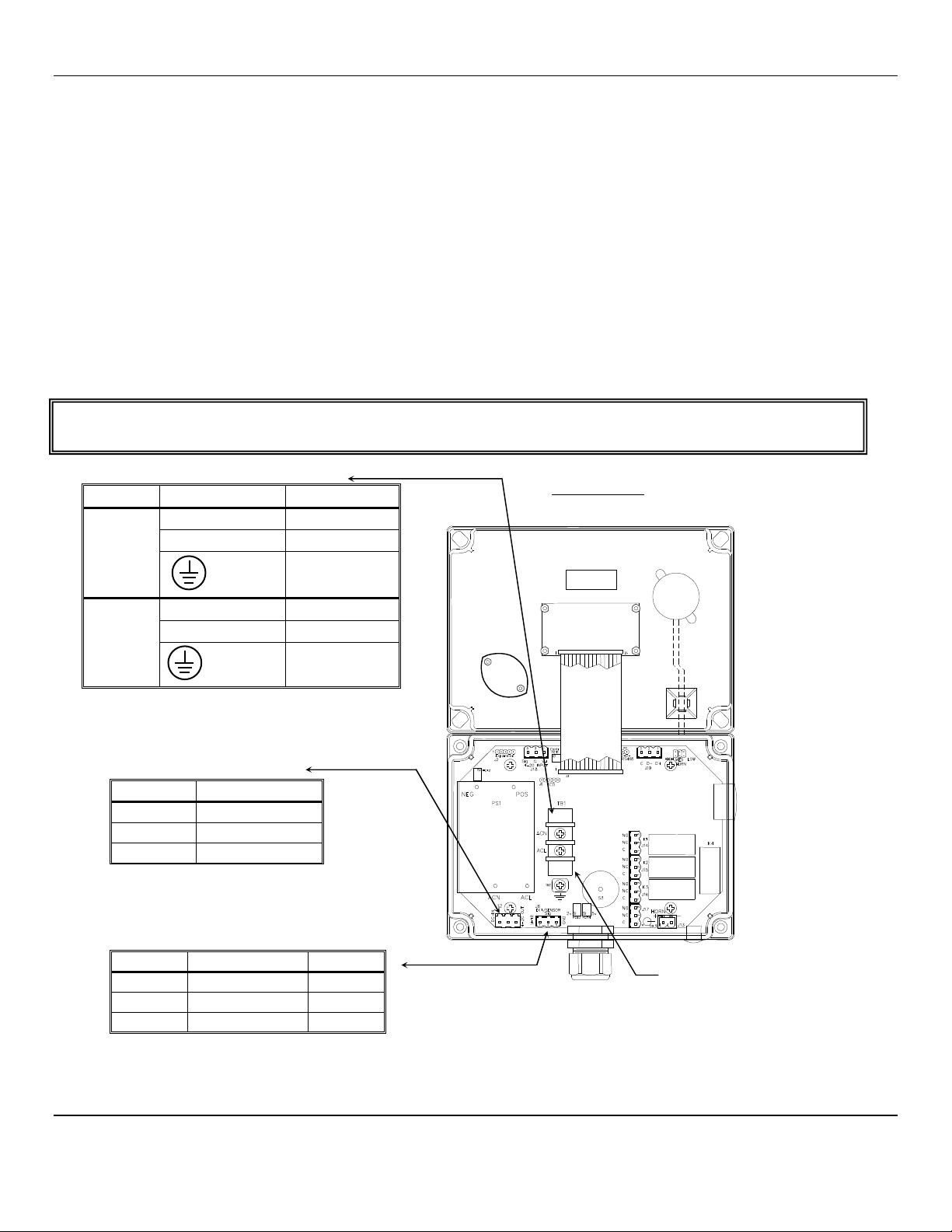
3.1.2 Power Supply
The input power can vary from 100 to 240 VAC, 50/60 Hz. Power should be connected to the Power Input Terminal TB1 and
the Ground screw. See Figure 4 for location. Instrument is supplied with a strain relief and a standard U.S. 3 prong power line
cord.
For DC wiring 24VDC may be wired to J12, (J12-1)position 1 + with ground connected to (J12-2)position 2.
Upon supplying power to the AM-5175:
The green power on LED is lit.
The display backlight is lit, and instrument will step through a start-up sequence: unit serial number and software revision
may be shown on the display.
The instrument may go into alarm briefly, but the sensors stabilize quickly. If the instrument persists in alarm, acknowledge the
alarm by pressing the SELECT button. If alarm persists longer than 30 minutes, call ENMET customer service personnel.
W
ARNING
:
Continuous gas detection and alarm systems (110VAC/220VAC / 24VDC/12VDC powered) become inoperative upon
loss of primary power. Contact factory for specifications and pricing of backup battery systems.
AC Power Supply Terminal: TB1
Label on PCB Function
110VAC TB1 ACN Neutral
TB1 ACL Line
Ground
Screw AC GND
220VAC TB1 ACN Neutral
Optional TB1 ACL Line
Ground
Screw AC GND
CAUTION: 110/220 VAC when applied
DC Power Supply/4-20mA
Terminal: J12
Position Function
1 + 24 V
DC
power
2 GND
3 4 - 20 mA out
Sensor Terminal: J8
Position Function Color
1 + Sensor Red
2 Sensor Signal White
3 Sensor Ground Black
Figure 4: Power Terminal Connections AM-5175
Cover Inside View
Opened Upward
Caution
: 110/220 Vac
when applied

AM-5175 ENMET Corporation
6
3.3 Relay Contacts
Relay contacts are available for each alarm; these are SPDT, rated at 10Amp at 110VAC, and may be latching or non-latching
as required by the application.
They are accessed on the terminals next to each relay see Figure 5. The contact positions are noted on the circuit board next to
each terminal.
The following table is for the relays in their un-energized state. This is also the alarm condition state. Non-failsafe configured
relays in the alarm state, are the reverse of the PC board labeling. Note that the Fault(FLT) relay cannot be set to operate in a
Non-Failsafe mode. Please see Table 1 below:
Table 1 : Relay Failsafe Settings
Alarm
Position
Alarm 1 J14 (K1)Relay 1 - NO Normally Open
J14 (K1)Relay 1 - NC Normally Closed
J14 (K1)Relay 1 - COM Common
Alarm 2 J15 (K2)Relay 2 - NO Normally Open
J15 (K2)Relay 2 - NC Normally Closed
J15 (K2)Relay 2 - COM Common
Alarm 3 J16 (K3)Relay 3 - NO Normally Open
J16 (K3)Relay 3 - NC Normally Closed
J16 (K3)Relay 3 - COM Common
Fault Alarm J17 (K4)Relay 4 - NO Normally Open
J17 (K4)Relay 4 - NC Normally Closed
J17 (K4)Relay 4 - COM Common
These relay contacts can be used to operate auxiliary alarms or other functions. The relay contacts are DRY, power must be
supplied. It is recommended that power for auxiliary equipment be supplied from an independent power source separate form
the AM-5175. Use the existing hole in the enclosure for wire to enter and exit and use appropriate cable fittings. Wiring
should be grouped together, VAC wires should be separated for VDC wires.
Figure 5: Relay Terminal Connections AM-5175
Relays
K1, K2, K3, K4
Relay Terminals
J14, J15, J16, J17
Sensor Terminal J8

AM-5175 ENMET Corporation
7
4.0 Operation
When the AM-5175 is installed as described in Section 3, and in clean air, the POWER green LED is on, the display is lit and
the information on the display is measurement of the target detected by the AM-5175.The red alarm and fault LEDs are not lit.
4.1 Start Up AM-5175
When the AM-5175 is first powered up, it goes through a series of momentary screens, which identify the instrument model
number, serial number and software revision. After all of the momentary screens have been displayed, the instrument arrives at
the Main Gas Display showing the gas concentration and unit of measurement.
Depending on transmitter configuration and calibration condition, the furthest right character in the display may flash a letter
indicating the instrument status. See the Section 4.1.1 below
4.1.1 Typical Start Up
When power is supplied to the AM-5175, the instrument will display the following sequence of information:
Typical start up sequence of information displayed.
Example of Typical Start Up Display Function
The instrument: Model
AM
-
5175
Example for reference only
The instrument: Serial Number
Example for reference only
The instrument: Software Revision
IF the right most character is a flashing
W
OR
The instrument is in Warm-up mode
This should last about 1 minute
The Signal Output is held at 4mA during warm-up
IF the right most character is a flashing
C
OR
The instrument has failed Calibration
The last good calibration values are retained, but the sensor may
not be responsive to gas
A new Calibration should be performed As Soon As Possible
OR
The instrument: Normal Display Mode
Measurement of the target gas
N
OTE
:
Software revision may cause variations of display output.
AM
-
5175
312
-
1256
S/W X.X
20.9
%
0ppm
20.9W
0pp
W
0ppC
20.9C
AM-5175 ENMET Corporation
8
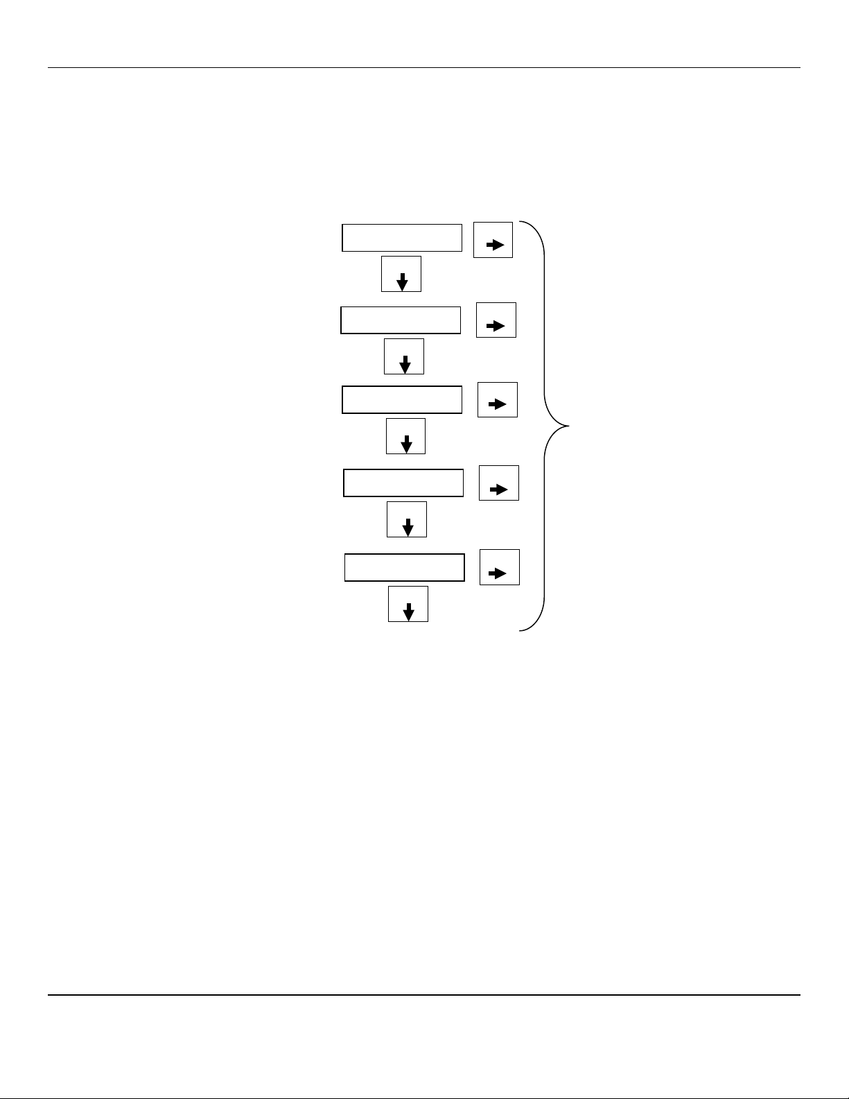
4.2 Normal Display Mode
When the AM-5175 is installed as described in section 3, and in clean air, the POWER green LED is on, the display is lit and
the information on the display in measurement units of ppm detected by the AM-5175.The red alarm and fault LEDs are not
lit.
To advance through displays of operational information press the MENU button.
N
OTE
:
Software revision may cause variations of display output.
See sequence of operational information below:
Display Measurement of the target gas
Press MENU button
Display indicates Alarm 1 Set point
Press MENU button
Display indicates Alarm 2 Set point
Press MENU button
Press SELECT button
To temporally disable audio
alarm, see Section 4.2.1
Display indicates Alarm 3 Set point
Press MENU button
Display indicates mA Span range
(Full Scale)
Press MENU button
Display returns to gas measurent
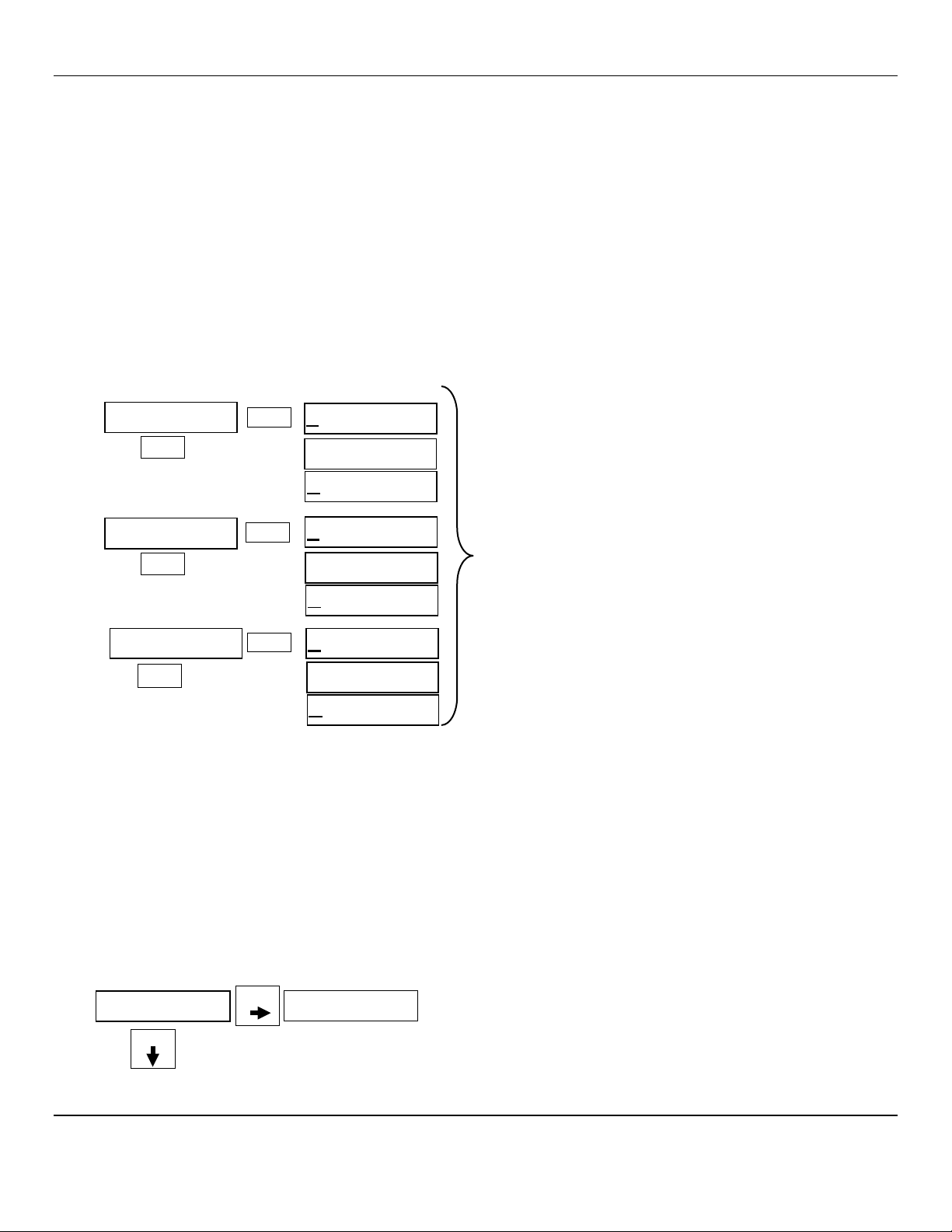
Operational Display Flow Chart
4.2.1 Alarm Conditions AM-5175
There are three alarm set points available. These alarm points are normally set at established safety levels, such as the OSHA
Permissible Exposure Limit (PEL) for toxic gases.
These alarm set points can be changed within limits; see the maintenance section of this manual for the procedure.
If the gas concentration increases above that of the alarm set point, the associated red LED is lit, the associated relay changes
state, and the audio alarm is activated.
Pressing the SELECT button can temporally disable the Audio Alarm. The horn will be disabled for about five minutes. If a
second alarm condition occurs during this time the horn will re-activate. If the alarm condition(s) have ended during this time
the horn will not re-activate.
0ppm
Menu
Select
A1: 05
Menu
Select
A2: 10
Menu
Select
A3: 20
Menu
Select
mA: 50
Menu
Select

AM-5175 ENMET Corporation
9
5.0 Maintenance
The AM-5175 maintenance menus are accessed by pressing the MENU button and SELECT button as described in the
maintenance menu section.
5.1 Maintenance Menus
CAUTION:Do Not Attempt A Span Procedure Without Calibration Gas Applied to The Sensor; if this is done, the instrument is
forced into a calibration fault mode.
Pushbutton switches control the MENU and SELECT functions. The MENU and SELECT button locations are indicated on the
display panel, see Figure 1. The MENU button is used to display the various menu options and make incremental changes to
numbers such as alarm points, calibrations gas, etc. The SELECT button is used to select that option, set zero or span digit.
To enter the maintenance menu press and hold the MENU button for 2 to 4 seconds
Table 2 indicates the maintenance menu sequence see Figure 6 for a detailed maintenance menu flow chart.
N
OTE
:
Software revision may cause variations of display output.
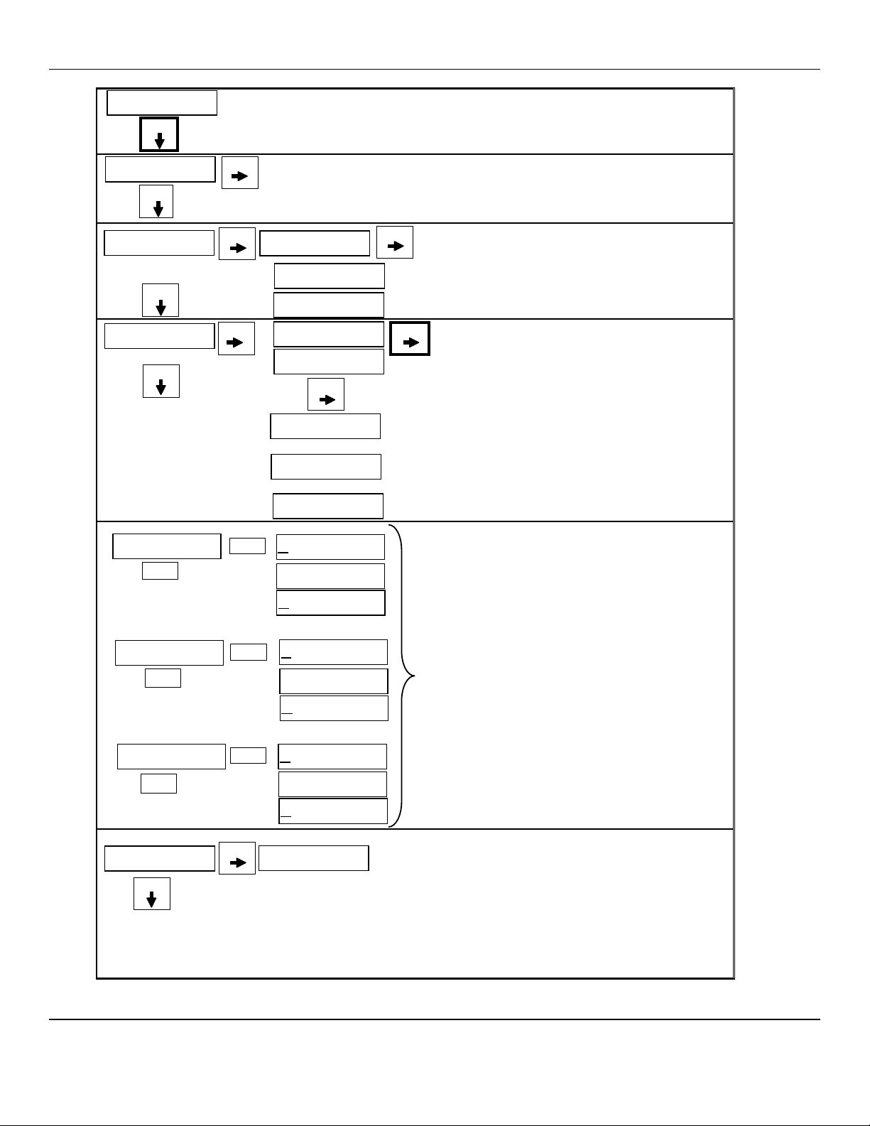
Table 2: AM-5175 Maintenance Menus Sequence
Example of Display Function
Normal Display Mode
Measurement of CO
Press and hold the MENU button for 2 – 4 seconds to enter the Maintenance Menu
The Power/Fault LED will flash Green – Red to indicate the AM-5175 is in Maintenance Mode
To exit the maintenance Menu and return to the
Normal Display Mode:
If intended function Press SELECT button
Press the MENU button to advance to the Zero procedure
Not Present for Oxygen Units
For adjusting Zero:
If intended function Press SELECT button
Press the MENU button to advance to the Span procedure
For adjusting the Span:
If intended function Press SELECT button
Press the MENU button to advance to each Alarm set point procedures
For adjusting the Alarm 1, 2 and 3 set points:
If Intended function Press SELECT button
Press the MENU button to advance the mA Span set point procedure
For adjusting the mA Span set point:
If intended function Press SELECT button
Pressing the MENU button without pressing the SELECT button will allow you to cycle through the menu options.
You must Press the SELECT button in order to initiate the desired operation.
5ppm
Exit
Zero
Span
mA Span
Alarm1
Alarm2
Alarm3
AM-5175 ENMET Corporation
10
N
OTE
:
Software revision may cause variations of display output.
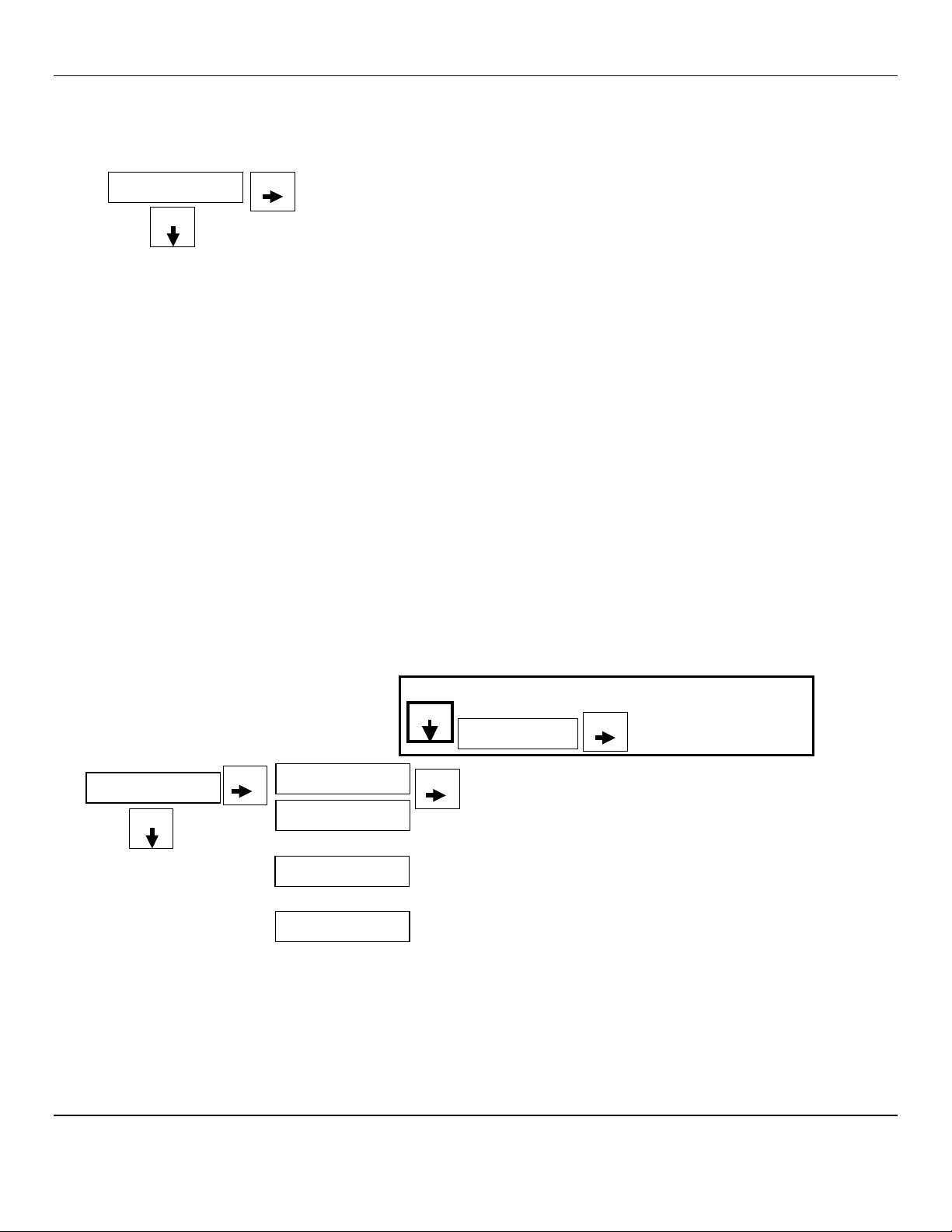
Normal Gas Display
5ppm
Menu Press and Hold the Menu button for 2 – 4 seconds to enter the Maintenance Menus
To change Alarm set points:
Press Menu switch until Alarm to be changed is displayed
Press Select switch to display the set point
The M
ENU
switch: changes digit indicated by underscore
cursor
The S
ELECT
switch: locks in the underscored digit and
moves to next digit
If change is not within range display returns to first digit
If change is within range display moves to Set Time Delay
Use M
ENU
and S
ELECT
switches as above to change time
delay. Between 0 and 5 seconds is allowed
If change is within range display moves to next menu
See Section 5.2.4
Λ- Indicates increasing alarm
V- Indicates decreasing alarm
SetTD
sec
0
Alarm3
S
ELECT
Λ
20
M
ENU
SetTD
sec
0
Alarm1
M
ENU
S
ELECT
Λ
5
SetTD
sec
0
Alarm2
M
ENU
S
ELECT
Λ
10
Exit
Press the Select button to return to the Normal Gas Display. See Section 5.2.1
Menu Press the Menu button to cycle through Maintenance Menus
Select
OR
Zero
Cal OK
If
the Zero signal is not within Preset Specs the AM
-
5175 will
display Bad ZERO
Menu
Bad ZERO
If
the Zero signal is within Preset Specs the AM-
5175 will display
Cal OK, See Section 5.2.2
P :
0
Press the Select button to initiate Zero adjustment
Not Present for Oxygen Units
Select
Select
OR
OR
Menu
P :
0
20
Apply
Cal Gas until signal value becomes stable
(about 1 to 4 minutes) See Figure 6
Press Select to enter the cal signal:
If cal is good display will indicate OK or Same
If cal is not within preset “range” display will
indicate Bad Sens
Cal OK
Same m
Bad Sens
Span
You can Press and
Hold
the
Select
button to
change the Calibration Gas Level
See Section 5.2.3
Select
Select
Select
To
return to Normal Gas Display:
Press M
ENU
button until EXIT is displayed
Then press S
ELECT
button
mA Span
Menu
Select
50
To change mA Span set point:
Press Menu button until mA Span is displayed
Press Select button to display the set point
The Menu button changes digit indicated by underscore cursor
The Select button locks underscored digit and moves to next digit
See Section 5.2.5
Figure
6:
AM-5175 Maintenance Menu Flow Chart
AM-5175 ENMET Corporation
11
5.2 Calibration of the AM-5175
Calibration is the process of setting the instrument up to read accurately when exposed to the target gas. The Zero function sets
the clean air reference point and the Span function sets the sensitivity of the instrument.
Initial Calibration: Wait at least 3 – 4 hours after initially supplying power to the AM-5175 instrument before initial
calibration, overnight is preferred. The AM-5175 has been pre-calibrated at the factory, and initial field calibration should
result in only fine-tuning to circuit, as well as a way to check that installation is successful. It is not necessary to open the
enclosure to make adjustment. The calibration functions are operated with pushbuttons from outside the enclosure through the
MENU and SELECT switches.
Calibration Zero and Span functions are two separate procedures. They operate independently of each other. It is
recommended that the Zero procedure be done prior to the Span procedure.
ENMET Corporation recommends at least quarterly calibration of the AM-5175 instrument.
Calibration equipment is available from ENMET Corporation to calibrate the AM-5175 instrument.
•Calibration adapter, a length of tubing with a regulator for the gas cylinder on one end, and a calibration cup to connect to
the sensor of the AM-5175 on the other.
•Gas cylinder, Zero gas 20.9% oxygen or Span gas, factory determined, varies by intent.
Generally, a cylinder of 20.9% Oxygen is used to provide a Zero point or fresh air reference for the calibration.
N
OTE
:
Software revision may cause variations of display output.
Menu
Select
Front View,
Attaching Calibration Cup
Side View,
Attaching Calibration Cup
Menu
Select
Front View
with Cal Cup attached
Side View
with calibration Adapter
Figure 7: Calibration Adapter
Sensor
Gas Cylinder
R
egulator
Calibration Cup
Calibration Cup
To Attach Calibration Cup:
Slide Down over the
retaining posts
To Remove Calibration Cup:
Slide Cup Up off the
retaining posts
Retaining Posts
2 places
Retaining Posts
2 places
AM-5175 ENMET Corporation
12
5.2.1 Exit Maintenance Menu
Exit maintenance, by pressing the Exit appears on the display. Press the SELECT button to return to the instrument Normal Gas
Display.
Example of Exit menu:
5.2.2 Zero Adjust
The ZERO function must be performed by exposing the AM-5175 instrument to clean fresh air. If the air at the sensor is in
question, use a cylinder of 20.9% oxygen to provide a clean air reference.
Enter the maintenance menu by pressing and holding MENU button for 2 to 4 seconds. See Figure 6, AM-5175 Maintenance
Menu flow chart.
After entering the maintenance menu, Press the MENU button until the Zero menu is displayed.
Press the SELECT button to perform a Zero.
The display will alternate between Zero and PV: To abort Zero function press and hold MENU button for 3 – 4 seconds,
Abort? will appear, press SELECT button to return to Zero.
Press the SELECT button to initiate a Zero adjustment.
An auto detect sequence is initiated. After 15 seconds, the AM-5175 will monitor the zero reading for stability.
If the reading stabilizes, within the pre-programmed perimeters, an automatic zero adjustment will be made.
Cal OK appears on the display and in 1 – 2 seconds, display will change to Span.
If you wish to Span the sensor press the SELECT button you are now ready to apply gas. Proceed to gas span step 2
If you wish to Exit the maintenance menu, press MENU button until Exit is displayed, then press SELECT button to return to
the instrument Normal Gas Display
If the reading does not stabilize, within 255 seconds, the procedure will be aborted. Sensor is outside of safe parameters
to be zeroed, the display will read Bad Zero. Repeat Section 5.2.2 Zero Adjust making sure to use a Zero gas of 20.9%
Oxygen. ENMET part number 03296-209.
N
OTE
:
.Zero adjust is Not Present for Oxygen Instruments
Example of Zero adjustment display:
N
OTE
:
Software revision may cause variations of display output.
OR
Zero
Cal OK
If
the Zero signal is not within Preset Specs the AM-5175
will display Bad Zero and return to
Zero menu
Select
Menu
Bad ZERO
If
the Zero signal is within Preset Specs the AM-5175 will
display Cal OK momentarily then advance to Span menu
PV: 0
Select
Press the Select button to force Zero adjustment
Zero
Not Present for Oxygen Instruments
Exit
Press the Select button to return to the Normal Gas Display.
Menu
Press the Menu button to cycle through Maintenance Menus
Select
Note:
You can Press and
Hold
the
Menu
button to abort Zero
When Abort? appears press Select button to
return to Zero menu
Abort?
Select
Menu
AM-5175 ENMET Corporation
13
5.2.3 Gas Span
It is recommended that the Zero Function be performed first.
Do not perform a calibration unless span gas is applied to sensor. Calibration can be aborted by pressing and holding the MENU
button for 3 – 4 seconds.
Enter the maintenance menu. See Figure 6, AM-5175 Maintenance Menu flow chart.
1. Press the MENU button until Span display.
2. Press the SELECT button to perform a Span procedure.
The display will alternate between the calibration gas concentration (Example: Cal 20) and a signal level (PV).
•To Abort calibration press and Hold MENU button for 3 – 4 seconds, “Abort?” will appear, press SELECT button to return
to Span.
•To change calibration gas level to be used, press and Hold SELECT button for 3 – 4 seconds, use menu button to change
digit and select button to move to next digit.
3. Attach the associated calibration gas cylinder to the calibration adapter. See Figure 7calibration adapter.
4. Open the valve to apply the calibration gas to the sensor.
An auto detect sequence is initiated after 30 seconds, the AM-5175 will monitor the cal reading for stability.
5. Watch for the signal level to stabilize. This should take about 1 – 4 minutes.
6. Once the signal level has stabilized,
If the Span is successful, Cal OK appears momentarily, then will advance to Alarm1 menu.
To exit cal, press MENU button until Exit appears and press SELECT button
If the sensor is outside of acceptable parameters, Bad Span is displayed.
If the sensor did not respond, an incompatible span gas was applied and the sensor did not respond at all,
Same mV is displayed then will return to Span.
If calibration is not successful, it is suggested that calibration be attempted again in 30-60 minutes.
If the sensor will not calibrate See Section 5.3 for sensor replacement.
7. Remove the calibration gas.
8. Press the MENU button to advance to Exit menu or desired menu.
N
OTE
:
Software revision may cause variations of display output.
Example of Calibration Display:
Menu
PV: 0
20
Apply
Cal Gas until signal value becomes stable (about 1 to 4
minutes) See Figure 7 Calibration Adapter
When cal signal is stable AM-5175 will automatically update:
If cal is good display will indicate OK or Same and advance to
Alarm1
If
cal is not within preset “range” display will indicate Bad Sens
or Same mV The AM-5175 will return to the Span Menu
To exit press Menu button until Exit appears and press Select
Cal OK
Span
PV: 0
Same mV
Bad Sens
OR
Select
Select
Note:
To change calibration gas level. Press and Hold the Select button to change the Calibration Gas Level
-Use the Menu button to change digits
-Use the Select button to move to next digit
Select
20
Note:
To abort calibration. Press and Hold the Menu button to abort Calibration
When “Abort?” appears press Select button to advance to desired menu
Abort?
Select
Menu
AM-5175 ENMET Corporation
14
5.2.4 Alarm Set Points
The AM-5175 has three alarm set points set at the factory. These alarm points are normally set at established safety levels.
Alarm set points can be changed within limits.
To change any of the three alarm points:
Enter the maintenance menu as shown in Figure 6 AM-5175 Maintenance Menu flow chart.
1. Press the MENU button until to display Alarm1 is displayed.
2. Press the SELECT button to initiate alarm set point change
3. Press the MENU button to change the digit indicated by the underscore cursor
Λ
- Indicates increasing alarm
V- Indicates decreasing alarm
4. Press the SELECT button to move the cursor to the next digit
When last digit is entered the AM-5175 will advance to the next menu
5.
Use M
ENU
and S
ELECT
switches as above to change time delay.
Between 0 and 5 seconds is allowed
6. Press the MENU button to advance to the next menu
NOTE: Alarms 2 and 3 can not be set below the Alarm 1 setting.
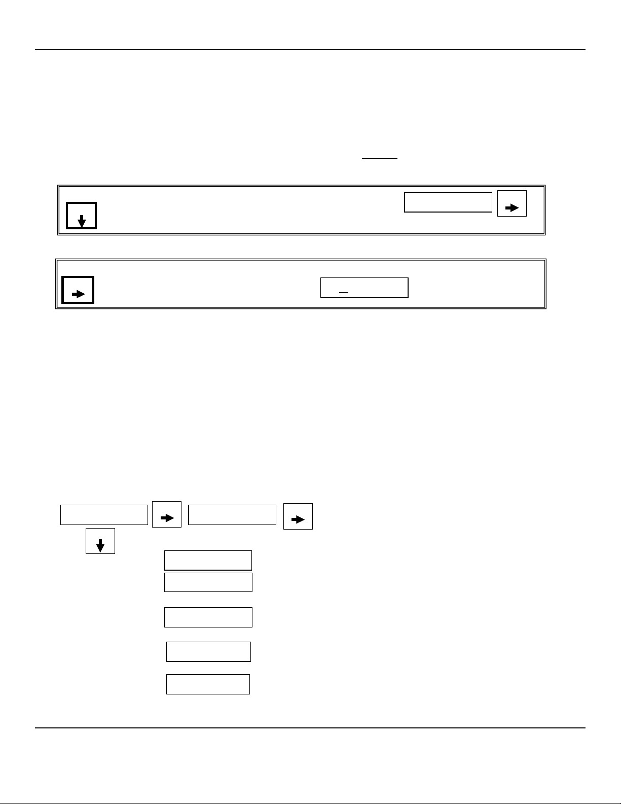
Example of Alarm Set Point menus:
N
OTE
:
Software revision may cause variations of display output.
5.2.5 mA Span Set
The AM-5175 4-20mA span range is set at the factory, normally to the full scale of the measurement and can be changed
within limits.
To change the span range:
Enter the maintenance menu as shown in Figure 6 AM-5175 Maintenance Menu flow chart.
1. Press the MENU button until to display Span is displayed.
2. Press the SELECT button to initiate the mA Span menu
3. Press the MENU button to change the digit indicated by the underscore cursor
4. Press the SELECT button to move the cursor to the next digit
When last digit is entered the AM-5175 will advance to the next menu
5. Press the MENU button to advance to the next menu
Example of mA Span menu:
mA Span
Menu
50
To change mA Span set points:
Press Menu button until mA Span is displayed
Press Select button to display the set point
The Menu button changes digit indicated by underscore cursor
The Select button locks underscored digit and moves to next digit
Select
To change Alarm set points:
Press Menu switch until Alarm to be changed is displayed
Press Select switch to display the set point
The M
ENU
switch: changes digit indicated by underscore
cursor
The S
ELECT
switch: locks in the underscored digit and
moves to next digit
If change is not within range display returns to first digit
If change is within range display moves to Set Time Delay
Use M
ENU
and S
ELECT
switches as above to change time
delay. Between 0 and 5 seconds is allowed
If change is within range display moves to next menu
Λ
- Indicates increasing alarm
V- Indicates decreasing alarm
Set D
sec
0
Alarm3
S
ELECT
Λ 20
MENU
Set Dsec
0
Alarm1
MENU
S
ELECT
Λ 5
Set D
sec
0
Alarm2
MENU
S
ELECT
Λ 10
AM-5175 ENMET Corporation
15
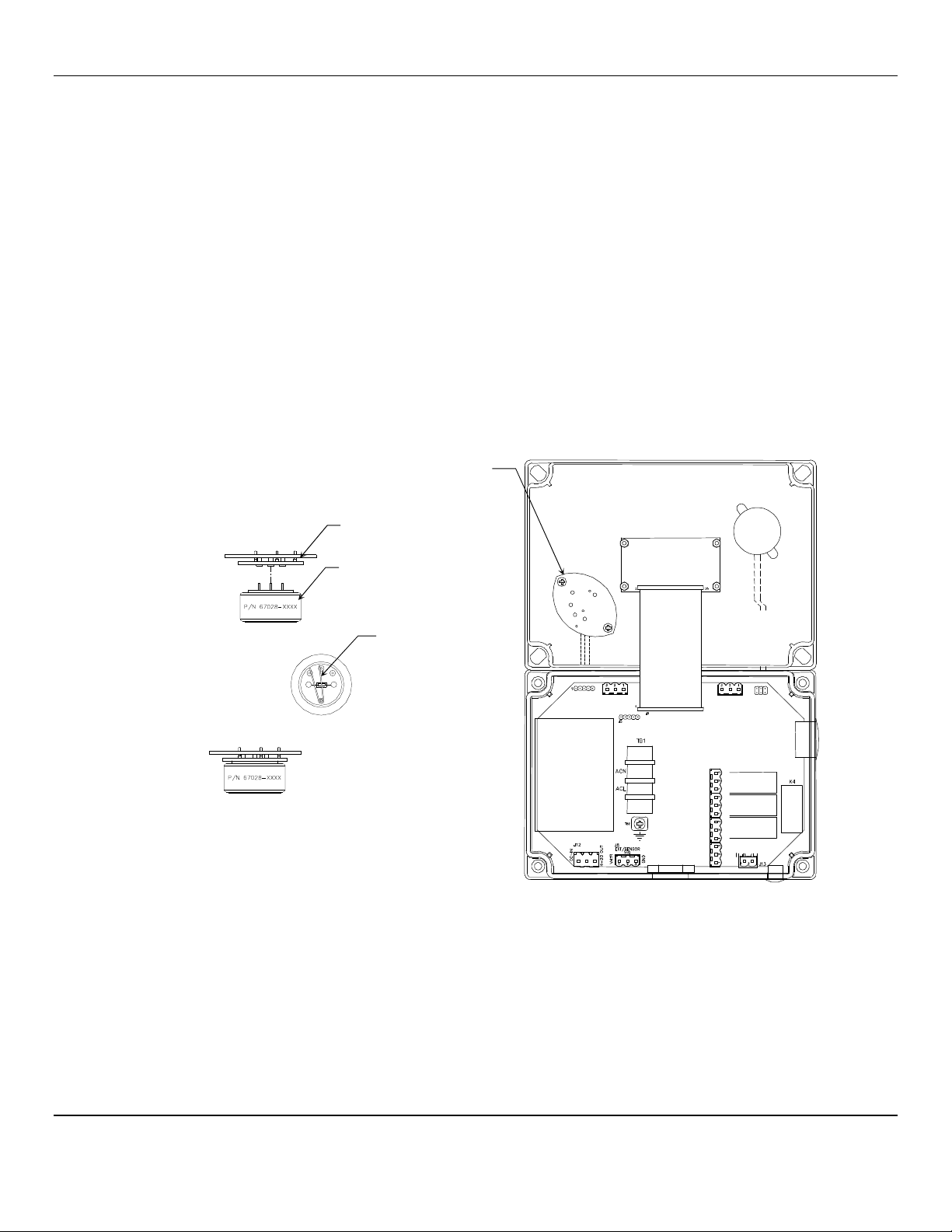
5.3 Sensor Replacement
W
ARNING
:
Power must be removed from the AM-5175 before this or any internal procedure. Failure to do so may cause
damage to equipment, bodily injury or death.
Sensors should be replaced when they can no longer be calibrated. Replacement sensor part numbers are listed in Section 6.0
of this manual. If you do not know the proper part number for your sensor, be sure to have the AM-5175 serial number
available when contacting your distributor or ENMET Corporation technical Support.
SENSOR REPLACEMENT PROCEDURE:
1. Obtain a new sensor. Make sure the sensor type is identical to your original sensor.
2. Disconnect the instrument for power.
3. Remove the 2 Sensor PC board retaining screws.
4. Unplug the sensor from the PC Board. See Figure 8
5. Plug the new sensor into the PC Board. See Figure 8
NOTE:If a shorting clip is present, remove the clip before plugging in the new sensor.
6. Replace the Sensor PC board and 2 retaining screws.
7. Reconnect the instrument to power.
8. Recalibrate the instrument (See Section 5.2).
Step 4. unplug sensor
Step 5.Remove clip if necessary
Plug in new sensor
Figure 8: AM-5175 Sensor Replacement
After the sensor has been installed, it is suggested to allow the sensor to stabilize for at least 3 – 4 hours, preferably over night.
5.3.1 A Factory calibration must be performed.
After entering the Maintenance menu, press and hold the MENU button for 2-4 seconds while viewing the Zero menu.
After 2-4 seconds, an F will appear on the far right hand side of the display. The F indicates that the instrument is in Factory
mode.
Perform the calibration Zero and Span procedures as outlined in Section 5.2. Be sure that the F is present when selecting the
Zero and Span functions.
The Factory calibration sets a calibration window for future standard instrument calibrations.
Sensor PC Board
Retaining Screws
2 places
Sensor PC Board
Sensor
Shorting Clip
If present

AM-5175 ENMET Corporation
16
6.0 Accessory and eplacement Parts
ENMET accessory part numbers:
Part number Description
03620-022 Calibration Cup
04834-004 Calibration Regulator Assembly for Steel Cylinder
03219-100 Gas Cylinder, 100 ppm CO in air, (34 Liter, Steel Cylinders)
03296-209 Gas Cylinder, Zero Gas, 20.9% oxygen in nitrogen, (34 Liter, Steel Cylinders)
04834-001 Calibration Regulator Assembly for Aluminum Cylinder
03314-020 Gas Cylinder, 20 ppm H
2
S in N
2
, (34 Liter, Aluminum Cylinders)
67028-0200 Sensor H
2
S
67028-1100 Sensor O
2
67028-1200 Sensor CO
73083-000 Carry Case
7.0 Technical Data and Specifications
Electrical Power 15 Amp fused branch circuit
100-240 V
AC
0.45A, 50/60 Hz
0.6A, 24V
DC
Operation Temperature: -20
°
to +40
°
C (-4
°
to +104
°
F)
Relative Humidity 10-99% RH, non-condensing
Mechanical Dimensions: 7.1 x 5.1 x 3 in(180x130x75mm)
Weight: 2 lbs (0.9 kg)
Material: Polycarbonate
Strain relief: 3 - 6.5mm OD
Outputs Relays: SPDT
Resistive Load Inductive Load
10A at 110 V
AC
7.5A at 110 V
AC
10A at 30 V
DC
5A at 30 V
DC
Analog: 4-20mA
Digital: RS-485-modbus
Audio: 105 dB at 30cm/12in
N
OTE
:All specifications stated in this manual may change without notice.

AM-5175 ENMET Corporation
17
8.0 WA ANTY
ENMET warrants new instruments to be free from defects in workmanship and material under normal use for a period of one
year from date of shipment from ENMET. The warranty covers both parts and labor excluding instrument calibration and
expendable parts such as calibration gas, filters, batteries, etc... Equipment believed to be defective should be returned to
ENMET within the warranty period (transportation prepaid) for inspection. If the evaluation by ENMET confirms that the
product is defective, it will be repaired or replaced at no charge, within the stated limitations, and returned prepaid to any
location in the United States by the most economical means, e.g. Surface UPS/FedEx Ground. If an expedient means of
transportation is requested during the warranty period, the customer is responsible for the difference between the most
economical means and the expedient mode. ENMET shall not be liable for any loss or damage caused by the improper use of
the product. The purchaser indemnifies and saves harmless the company with respect to any loss or damages that may arise
through the use by the purchaser or others of this equipment.
This warranty is expressly given in lieu of all other warranties, either expressed or implied, including that of merchantability,
and all other obligations or liabilities of ENMET that may arise in connection with this equipment. ENMET neither assumes
nor authorizes any representative or other person to assume for it any obligation or liability other than that, which is set forth
herein.
NOTE: When returning an instrument to the factory for service:
Be sure to include paperwork.
A purchase order, return address and telephone number will assist in the expedient repair and return of your unit.
Include any specific instructions.
For warranty service, include date of purchase
If you require an estimate, please contact ENMET Corporation.
There are Return for Repair Instructions and Form on the last pages of this manual. This Form can be copied or used as needed.
Manual part number
80003-551
October 2007
MCN-408, 11/18/08
MCN-421, 04/28/09
MCN-14-003, 03/20/14
Notes:

PO Box 979
680 Fairfield Court
Ann Arbor, Michigan 48106-0979
734.761.1270 Fax 734.761.3220
Returning an Instrument for Repair
ENMET instruments may be returned to the factory or any one of our Field Service Centers for regular repair
service or calibration. The ENMET Repair Department and Field Service Centers also perform warranty
service work.
When returning an instrument to the factory or service center for service, paperwork must be included which
contains the following information:
A purchase order number or reference number.
A contact name with return address, telephone and fax numbers
Specific instructions regarding desired service or description
of the problems being encountered.
Date of original purchase and copy of packing slip or invoice
for warranty consideration.
If a price estimate is required, please note it accordingly and be
sure to include a fax number.
Providing the above information assists in the expedient repair and return of your unit.
Failure to provide this information can result in processing delays.
ENMET charges a one hour minimum billing for all approved repairs with additional time billed to the closest
tenth of an hour. All instruments sent to ENMET are subject to a minimum evaluation fee, even if returned
unrepaired. Unclaimed instruments that ENMET has received without appropriate paperwork or attempts to
advise repair costs that have been unanswered, after a period of 60 days, may be disposed of or returned
unrepaired COD with the evaluation fee.
Service centers may have different rates or terms. Be sure to contact them for this information.
Repaired instruments are returned by UPS/FedEx Ground and are not insured unless otherwise
specified. If expedited shipping methods or insurance is required, it must be stated in your paperwork.
Note: Warranty of customer installed components.
If a component is purchased and installed in the field, and fails within the warranty term, it can be
returned to ENMET and will be replaced, free of charge, per ENMET’s returned goods procedure.
If the entire instrument is returned to ENMET Corporation with the defective item installed, the item will
be replaced at no cost, but the instrument will be subject to labor charges at half of the standard rate.
Table of contents
Other ENMET Monitor manuals


