enphase IQ 7 User manual
INSTALLATION AND OPERATION MANUAL
June 11, 2020 141-00047-01
Enphase IQ 7, IQ 7+, IQ 7X, and IQ 7A
Micros with EN4 Bulkhead
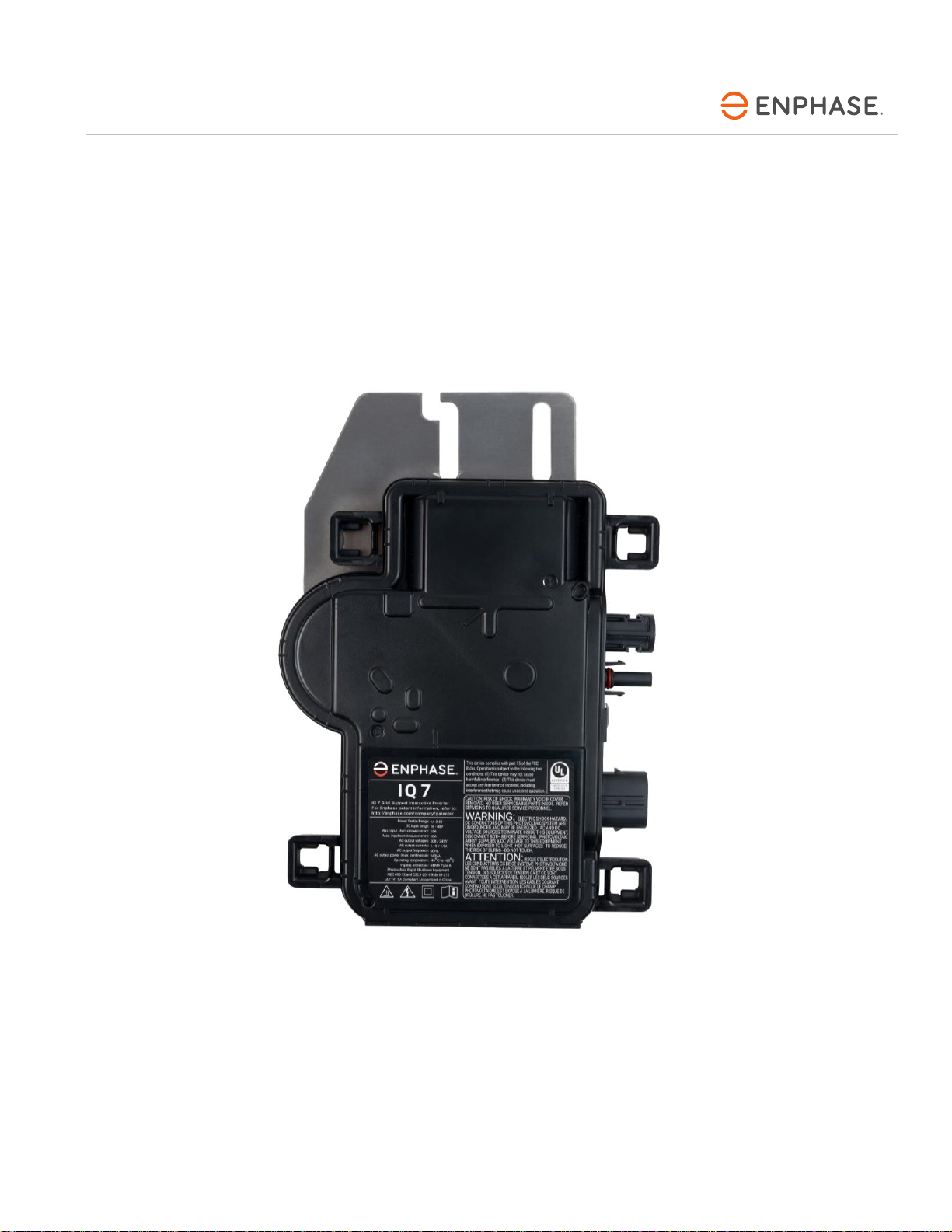
IQ 7 Series Micro with EN4 Bulkhead

IQ 7 / IQ 7+ / IQ 7X / IQ 7A with EN4 Bulkhead Installation and Operation
© 2020 Enphase Energy Inc. All rights reserved. 141-00047-01
2
Corporate Headquarters Contact Information
Enphase Energy Inc.
47281 Bayside Parkway
Fremont, CA 94538 USA
enphase.com/en-us/support/contact
FCC Compliance
This equipment has been tested and found to comply with the limits for a Class B digital device, pursuant
to part 15 of the FCC Rules. These limits are designed to provide reasonable protection against harmful
interference in a residential installation. This equipment generates, uses and can radiate radio frequency
energy and, if not installed and used in accordance with the instructions, may cause harmful interference
to radio communications. However, there is no guarantee that interference will not occur in a particular
installation. If this equipment does cause harmful interference to radio or television reception, which can
be determined by turning the equipment off and on, you are encouraged to try to correct the interference
by one or more of the following measures:
•Reorient or relocate the receiving antenna.
•Increase the separation between the equipment and the receiver.
•Connect the equipment into an outlet on a circuit different from that to which the receiver is
connected.
•Consult the dealer or an experienced radio/TV technician for help.
Changes or modifications not expressly approved by the party responsible for compliance may void the
user’s authority to operate the equipment.
Other Information
Product information is subject to change without notice. All trademarks are recognized as the property of
their respective owners.
User documentation is updated frequently; Check the Enphase website (enphase.com/support) for the
latest information.
To ensure optimal reliability and to meet warranty requirements, the Enphase Microinverter must be
installed according to the instructions in this manual. For warranty text refer to enphase.com/warranty.
For Enphase patent information refer to enphase.com/company/patents/.
© 2020 Enphase Energy Inc. All rights reserved. Enphase, the Enphase logo, IQ 7, IQ 7+, IQ 7X, IQ 7A,
IQ Envoy, IQ Combiner, IQ Microinverter, Installer Toolkit, Enlighten and other trademarks or service
names are the trademarks of Enphase Energy, Inc. Data subject to change.
Audience
This manual is intended for use by professional installation and maintenance personnel.

IQ 7 / IQ 7+ / IQ 7X / IQ 7A with EN4 Bulkhead Installation and Operation
© 2020 Enphase Energy Inc. All rights reserved. 141-00047-01
3
Table of Contents
Important Safety Information .......................................................................................................................................... 5
Read this First.................................................................................................................................................. 5
EN4 Bulkhead Microinverters........................................................................................................................... 5
Product Labels ................................................................................................................................................. 5
Safety and Advisory Symbols........................................................................................................................... 5
IQ 7 Series Microinverter Safety Instructions................................................................................................... 6
PV Rapid Shutdown Equipment (PVRSE) ....................................................................................................... 8
The Enphase IQ System................................................................................................................................................. 9
How the Enphase IQ Series Micros Work...................................................................................................... 10
System Monitoring..................................................................................................................................... 10
Optimal Reliability...................................................................................................................................... 10
Ease of Design........................................................................................................................................... 10
Planning for Microinverter Installation........................................................................................................................... 11
Compatibility................................................................................................................................................... 11
About EN4 Bulkhead Microinverters .............................................................................................................. 12
Grounding Considerations.............................................................................................................................. 12
Branch Circuit Capacity.................................................................................................................................. 13
Utility Service Requirements.......................................................................................................................... 13
Wire Lengths and Voltage Rise...................................................................................................................... 13
Lightning and Surge Suppression.................................................................................................................. 14
Parts and Tools Required............................................................................................................................................. 14
Enphase Equipment....................................................................................................................................... 14
Other Items..................................................................................................................................................... 14
Enphase Microinverter Installation................................................................................................................................ 15
Step 1: Position the Enphase Q Cable........................................................................................................... 16
Step 2: Position the Enphase Q Aggregator or Junction Box ........................................................................ 16
Step 3: Mount the Microinverters ................................................................................................................... 17
Step 4: Create an Installation Map................................................................................................................. 18
Step 5: Manage the Cabling........................................................................................................................... 19
Step 6: Connect the Microinverters................................................................................................................ 19
Step 7: Terminate the Unused End of the Cable............................................................................................ 20
Step 8: Complete Installation of the Enphase Q Aggregator or Junction Box................................................ 21
Step 9: Connect the PV Modules................................................................................................................... 21
Step 10: Energize the System........................................................................................................................ 22
Set Up and Activate Monitoring...................................................................................................................... 22
Troubleshooting............................................................................................................................................................ 23
Status LED Indications and Error Reporting .................................................................................................. 23
LED Operation........................................................................................................................................... 23
DC Resistance Low –Power Off Condition............................................................................................... 23
Other Faults............................................................................................................................................... 24
Troubleshoot an Inoperable Microinverter...................................................................................................... 25
Disconnect a Microinverter............................................................................................................................. 26
Install a Replacement Microinverter............................................................................................................... 27

IQ 7 / IQ 7+ / IQ 7X / IQ 7A with EN4 Bulkhead Installation and Operation
© 2020 Enphase Energy Inc. All rights reserved. 141-00047-01
4
Ordering Replacement Parts.......................................................................................................................... 29
Enphase Q Cable Planning and Ordering...................................................................................................... 29
Connector Spacing Options ........................................................................................................................... 29
Cabling Options.............................................................................................................................................. 29
Enphase Q Cable Accessories....................................................................................................................... 30
Technical Data.............................................................................................................................................................. 31
Technical Considerations............................................................................................................................... 31
Specifications................................................................................................................................................. 32
IQ7-60-E-US Microinverter Specifications................................................................................................. 32
IQ7PLUS-72-E-US Microinverter Specifications........................................................................................ 35
IQ7X-96-E-US Microinverter Specifications............................................................................................... 37
IQ7A-72-E-US Microinverter Specifications............................................................................................... 39
Q Cable Specifications............................................................................................................................... 41
Enphase Connector Ratings...................................................................................................................... 41
Enphase Installation Map............................................................................................................................... 42
Sample Wiring Diagram ................................................................................................................................. 43
IQ 7 / IQ 7+ / IQ 7X / IQ 7A with EN4 Bulkhead Installation and Operation
© 2020 Enphase Energy Inc. All rights reserved. 141-00047-01
5
Important Safety Information
Read this First
This manual contains important instructions for use during installation and maintenance of the IQ 7™Series
Microinverters with the Enphase EN4 bulkhead.
EN4 Bulkhead Microinverters
IMPORTANT: Enphase IQ Series EN4 Microinverters include AC and DC connectors integrated into the microinverter
bulkhead. The AC port of the Enphase EN4 bulkhead connects to an Enphase Q Cable or Enphase Field Wireable
Connector. The DC port of the EN4 bulkhead has been evaluated by UL for intermatability with TE PV4-S
SOLARLOK connectors, and several other connectors, that have been Listed and identified for intermatability with the
Enphase EN4 bulkhead connector, which allows you to plug them directly into the IQ7 Series microinverter with EN4
bulkhead. For other connector combinations, Enphase bulkhead adapters are required.
An IQ Envoy is required to monitor performance of the IQ Microinverters. The Q Accessories work only with Enphase
IQ Series Microinverters.
Product Labels
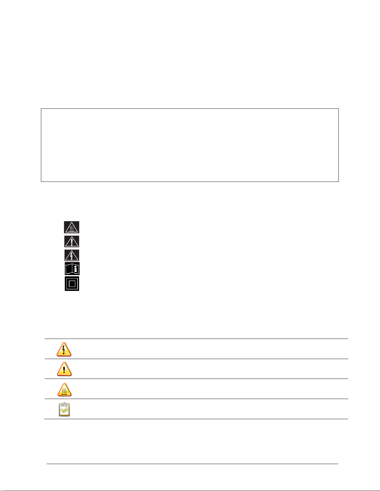
The following symbols appear on the product label and are described here:
WARNING: Hot surface.
DANGER: Refer to safety instructions.
DANGER: Risk of electrical shock.
Refer to manual
Double-insulated
Safety and Advisory Symbols
To reduce the risk of electric shock, and to ensure the safe installation and operation of the EnphaseIQ System, the
following safety symbols appear throughout this document to indicate dangerous conditions and important safety
instructions.
DANGER:
This indicates a hazardous situation, which if not avoided, will result in death or serious injury.
WARNING:
This indicates a situation where failure to follow instructions may be a safety hazard or cause
equipment malfunction. Use extreme caution and follow instructions carefully.
WARNING:
This indicates a situation where failure to follow instructions may result in burn injury.
NOTE:
This indicates information that is very important for optimal system operation. Follow instructions
closely.
Other manuals for IQ 7
7
This manual suits for next models
3
Table of contents
Other enphase Camera Accessories manuals


Popular Camera Accessories manuals by other brands


Trojan
Trojan GC2 48V quick start guide

Calumet
Calumet 7100 Series CK7114 operating instructions

Ropox
Ropox 4Single Series User manual and installation instructions

Cambo
Cambo Wide DS Digital Series Main operating instructions

Samsung
Samsung SHG-120 Specification sheet

Ryobi
Ryobi BPL-1820 Owner's operating manual