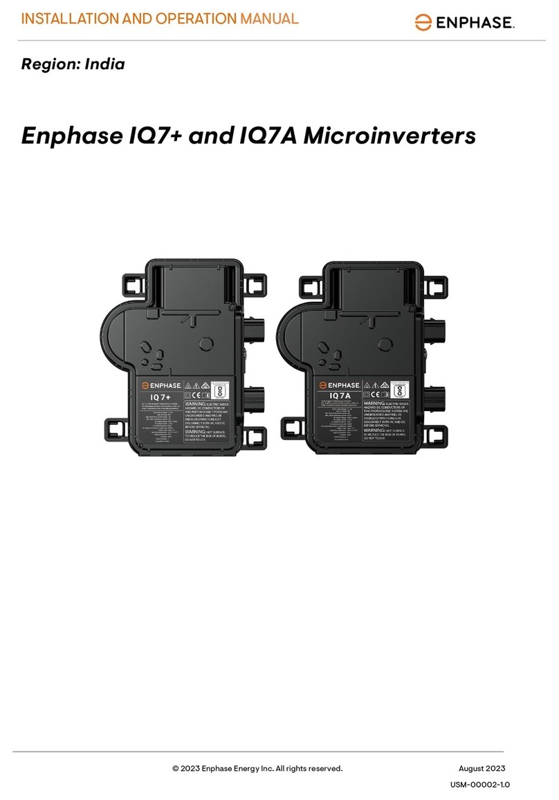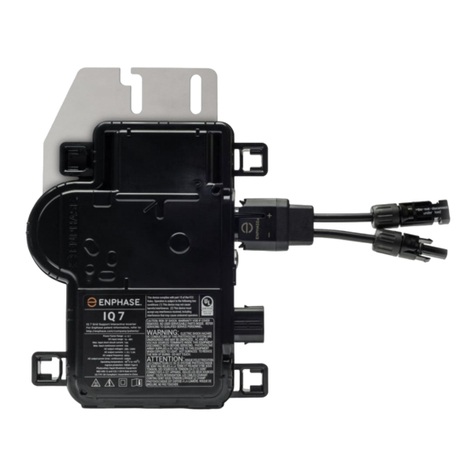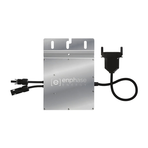
M215 Installation and Operation
2013 Enphase Energy Inc. 141-00012 Rev 05
Table of Contents
Important Safety Information.........................................................................................................................4
Read this First..................................................................................................................................................4
Safety Instructions ...........................................................................................................................................4
The Enphase Microinverter System..............................................................................................................5
How the Microinverter Works...........................................................................................................................6
System Monitoring.......................................................................................................................................6
Optimal Reliability........................................................................................................................................6
Ease of Design............................................................................................................................................6
Planning for Microinverter Installation...........................................................................................................7
Compatibility and Capacity ..............................................................................................................................7
Electrical Compatibility ................................................................................................................................7
Branch Circuit Capacity...............................................................................................................................7
Parts and Tools Required................................................................................................................................8
Enphase Equipment....................................................................................................................................8
Other Items..................................................................................................................................................8
Lightning and Surge Suppression....................................................................................................................8
Enphase Microinverter Installation................................................................................................................9
Step 1: Measure AC Voltage at the Electrical Utility Connection...................................................................10
Step 2: Install the AC Branch Circuit Junction Box........................................................................................11
Step 3: Position the Enphase Engage Cable.................................................................................................12
Step 4: Attach the Microinverters to the PV Racking .....................................................................................13
Step 5: Ground the System............................................................................................................................14
Step 6: Dress the Engage Cable ...................................................................................................................15
Step 7: Connect the Microinverters................................................................................................................16
Step 8: Terminate the Unused End of the Engage Cable..............................................................................17
Step 9: Connect the Engage Cable to AC Junction Box(es)..........................................................................18
Step 10: Complete the Installation Map.........................................................................................................19
Step 11: Connect the PV Modules.................................................................................................................19
Commissioning and Operation....................................................................................................................20
Energize the System......................................................................................................................................20
Build the Virtual Array....................................................................................................................................20
M215 Operation.............................................................................................................................................20
Troubleshooting ..........................................................................................................................................21
Status LED Indications and Error Reporting..................................................................................................21
Startup LED Operation: .............................................................................................................................21
Post-Startup LED Indications.....................................................................................................................21
GFDI Fault.................................................................................................................................................21
Other Faults...............................................................................................................................................21
Troubleshoot an Inoperable Microinverter .....................................................................................................22
Disconnect a Microinverter from the PV Module............................................................................................24
Install a Replacement Microinverter...............................................................................................................25
Technical Data ............................................................................................................................................26
Technical Considerations...............................................................................................................................26
M215 Specifications.......................................................................................................................................26
Engage Cable Specifications.........................................................................................................................28
Engage Cable Planning and Ordering Information ........................................................................................29
Selecting Cable Type ................................................................................................................................29
Connector Spacing Options.......................................................................................................................29
Voltage Types and Conductor Count.........................................................................................................30
Racking Compatibility................................................................................................................................30
Cabling Length Options.............................................................................................................................30
Planning for Cable Lengths and Type .......................................................................................................30
Enphase Installation Map...............................................................................................................................32
M215 Dimensions..........................................................................................................................................33
Sample Wiring Diagram: M215, 240 VAC......................................................................................................34
Sample Wiring Diagram: M215, 208 VAC......................................................................................................35


