Anaheim Automation MBC25P11 User manual

1
#L010128 June 2002
MBC25P11
Programmable Pulse Generator/Driver
User’s Guide
4985 E. Landon Drive Anaheim, CA 92807
(714) 992-6990 fax: (714) 992-0471
website: www.anaheimautomation.com
ANAHEIM AUTOMATION
July 2018

2
#L010128 June 2002
Table of Contents
Features ................................................................................................................................................... 3
Introduction............................................................................................................................................... 3
Motion Proles and Running the Pulse Generator ................................................................................... 3
Operation with Ramp Down Option.......................................................................................................... 4
Operation without Ramp Down Option..................................................................................................... 4
Operation with Soft and Hard Limits......................................................................................................... 4
LEDs......................................................................................................................................................... 5
Baud Rates............................................................................................................................................... 5
Inputs and Outputs ................................................................................................................................... 5
Connector Descriptions ............................................................................................................................ 6
Ordering Information................................................................................................................................. 7
Specications ........................................................................................................................................... 7
Dimensions and Jumper/Potentiometer Locations................................................................................... 8
Wiring Diagrams....................................................................................................................................... 8
Jumper Functions..................................................................................................................................... 9
Microstep Modes ...................................................................................................................................... 9
Setting the Output Current........................................................................................................................ 9
Reducing Output Current.......................................................................................................................... 9
Determining Output Current ................................................................................................................... 10
Step Motor Congurations...................................................................................................................... 10
Connecting the Step Motor......................................................................................................................11
Circuit Protection .....................................................................................................................................11
Functions................................................................................................................................................ 12
SMPG10WIN Software........................................................................................................................... 13
Installation .............................................................................................................................................. 13
Getting Started ....................................................................................................................................... 13
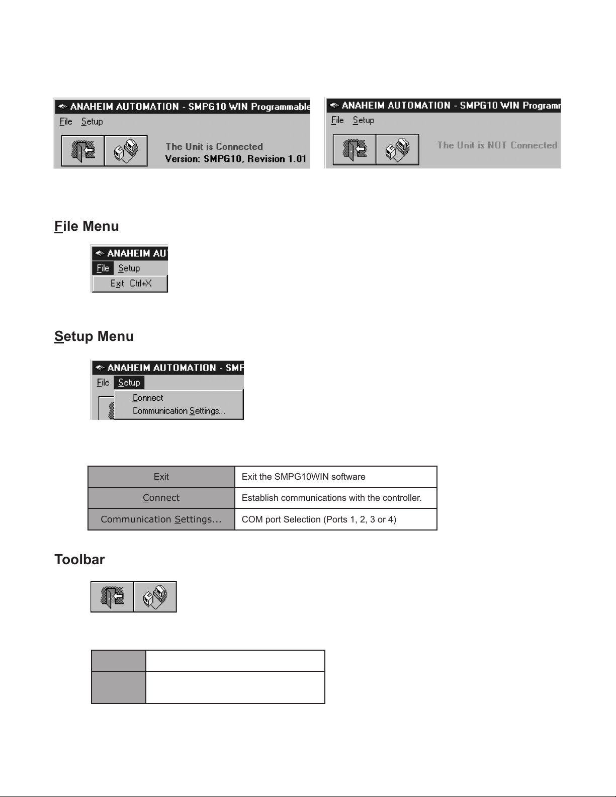
“The Unit is Connected” / “The Unit is NOT Connected”........................................................................ 14
File Menu................................................................................................................................................ 14
Setup Menu ............................................................................................................................................ 14
Toolbar.................................................................................................................................................... 14
Program Window.................................................................................................................................... 15
Direct Talk Mode..................................................................................................................................... 16
COM Port Settings.................................................................................................................................. 16
Unit Selection ......................................................................................................................................... 16
Instructions ............................................................................................................................................. 16
Troubleshooting...................................................................................................................................... 20
Error Codes ............................................................................................................................................ 21
ASCII Table for Direct Mode ................................................................................................................... 21
Torque Speed Curves............................................................................................................................. 22
Copyright ................................................................................................................................................ 22
July 2018

3
#L010128 June 2002
Introduction
The MBC25P11 is an economical single axis step motor driver integrated with a programmable pulse
generator. The MBC25P11 microstep driver/pulse generator has an output current capability of 0.5A
minimum to 2.5A maximum (peak rating). The MBC25P11 driver operates with a DC voltage of 12VDC to
35VDC. The MBC25P11’s internal PG (pulse generator) has four different programmable motion proles.
The MBC25P11 also has directional soft and hard limit switch inputs, a busy output and a clock output
that can be used for daisy chaining drivers together. The MBC25P11 driver features direction control and
motor current On/Off capabilities. The “Reduce Current Enabled” feature automatically reduces motor
current to 70% of the set value. The driver has built in features to indicate power on (green LED), running
(yellow LED) and error conditions (red LED). The MBC25P11 has various step resolutions that can be
implemented. These divisions range from 200 steps/rev to 1600 steps/rev. The bipolar drive conguration
handles 4, 6, and 8 lead step motors and is also equipped with short circuit, over temperature and crossover
current protection. The MBC25P11 communicates via RS232 communication. The easy to use Windows
software, SMPG10WIN, is used to directly set up to four different motion proles.
Features
• Output Current of 2.5A Peak
• 200 to 1600 Steps/Revolution (1, 2, 4 and 8 Selectable Step Operation)
• Drives Two Motors In Series
• On-Board Programmable Pulse Generator
• Pulses From 77Hz to 15kHz
• Directional Soft and Hard Limit Switch Inputs
• Clock Output for Daisy Chaining
• Busy Output
• Motor On/Off Input and Automatic Current Reduction
• Short Circuit Protection
Motion Proles and Running the Pulse Generator
The programmable pulse generator has the ability to store up to four different motion proles. The proles
include a base speed (starting speed), a maximum speeds (running speed) and acceleration/deceleration.
The base speed has a range of 77-3500 Hz, the maximum speed has a range of 77 Hz-15 kHz, and the
acceleration/deceleration has a range of 1-255. A seperate command is used to control the ramp down
prole. The ramp down prole lets the user have the option to either ramp down to base speed and stop
(soft stop), or to hard stop once the Run input is released. The deceleration option is the same for all four
motion proles.
There are “two ways” to get the pulse generator to run. The rst way is to directly control it from the
computer with software. Once the motion proles have been set, the pulse generator is ready to run.
From the software, the user can select which prole to run and then hit the run button. There are then
several different ways to stop motion. To ramp down to base speed and continue to run at base speed,
a soft limit command needs to be sent. This is done by either hitting the soft limit button or a physical
limit switch trigger of the soft+ or soft- depending on direction. To stop all motion, a hard limit command
needs to be sent. This is done by either hitting the hard limit button or a physical limit switch trigger of the
hard+ or hard- depending on direction. The second way to make the pulse generator run is to activate the
Run input. When this input is activated, it looks to see what speed prole input is set. If no speed prole
is set then the default is Prole 1. To stop motion, release the Run input. When this input is released, the
deceleration option will then either ramp down to base speed and stop or just hard stop. If a soft+ or soft
limit switch is activated when the Run input is active, the pulse generator will ramp down to base speed
and keep running. If a hard+ or hard- limit switch is activated when the Run input is active, the motor will
stop immediatley.
July 2018

4
#L010128 June 2002
A B C
Max Speed
Base Speed
Off
Time
Speed
Operation with Ramp Down Option
A) Run is activated; Starts at base speed and immediately ramps up to max speed.
B) Run is still active; Max speed is reached (keeps running at max speed).
C) Run is inactivated; Motor ramps down.
D) Pulses automatically stop when base speed is reached.
A B C D
Max Speed
Base Speed
Off
Time
Speed
Operation without Ramp Down Option
A) Run is activated; Starts at base speed and immediately ramps up to max speed.
B) Run is still active; Max speed is reached (keeps running at max speed).
C) Run is inactivated; Motor stops imediately.
A) Run is activated; Starts at base speed and immediately ramps up to max speed.
B) Run is still active; Max speed is reached (keeps running at max speed).
C) Run is still active; Soft limit is hit; Motor ramps down to base speed and keeps running.
D) Run is still active; Base speed is reached (keeps running at base speed).
E) Run is inactivated or Hard limit is hit; Motor stops imediately.
Operation with Soft and Hard Limits
A B C D
Max Speed
Base Speed
Off
Time
Speed
E
July 2018

5
#L010128 June 2002
LEDs
When powered and operated properly, the status LED will be green. When an error occurs, the LED will
change to RED and an error code will be generated in the error code register. To read and clear the error
with the software, click on the “Verify Parameters” button located in the “Motion Tab”. To read and clear
the error while in “Direct Mode” use the “!” command. Once the error has been read and cleared, the LED
will return to green and the error code register will be cleared. Refer to the table in section 5 for a list of
the error codes. When the pulse generator is running the yellow LED will be on. Refer to the dimension
drawing for location of the LEDs. For more detail on “Direct Mode” refer to the Direct Talk Mode section
of user’s guide.
Baud Rates
A term used frequently in serial data communications. A “baud” is dened as the reciprocal of the shortest
pulse duration in a data word signal, including start, stop, and parity bits. This is often taken to mean the
same as “bits per second”, a term that expresses only the number of “data” bits per second. Very often,
the parity bit is included as an information or data bit. The MBCPG211only accepts a baud rate of 9600.
Inputs and Outputs
Inputs: All inputs (except limit inputs) are either pulled up to 5VDC or pulled down to 0VDC based on
JP1. For pullups place JP1 in position 1-2, for pulldowns place JP1 in position 2-3. A logic “0” activates
inputs that are pulled up, while a logic “1” activates an input that is pulled down. An unconnected input
will always remain inactive. (Refer to Dimensions and Jumper/Potentiometer Locations drawing for JP1)
Direction: When this input is not active, the motor will be moving in the clockwise or “+” direction. When
this input is active, the motor will move in the counterclockwise or “-“ direction. This input can be overridden
by sending a + or - command to the pulse generator. When two motors are used, the second motor will
move in the opposite direction by default.
On/Off: When this input is not active, the motor will be enabled or energized. When this input is active,
the motor will be disabled or de-energized.
Run: When this input is not active, the pulse generator is stopped and will not output any pulses. When
this input is active the pulse generator will output pulses starting at the base speed rate and will ramp up
and output pulses at the max speed rate. When this input is released, the pulse generator will ramp down
to base speed and stop or hard stop depending on the deceleration option.
Speeds: These inputs are used to select one of the four proles when the run input is activated. To use
prole 2, then activate Speeds 2, to use prole 3, then activate Speeds 3, and to activate prole 4, then
activate Speeds 4. Activate only one of these three inputs at once. If none of the inputs are active, then
prole 1 will be used. (Refer to both the Motion Tab and Wiring Diagrams for illustrations)
Soft Limits: These two inputs are active low and are controlled by the direction of the pulse generator.
When the pulse generator is running in the positive direction only soft+ will work. When the pulse generator
is running in the negative direction then only soft- will work. When pulled low the pulse generator will ramp
down to base speed and continue running until a hard limit is reached or the run input is released.
Negative Going Inputs (Pull Up)Positive Going Inputs (Pull Down)
July 2018

6
#L010128 June 2002
Hard Limits: These two inputs are active low and are controlled by the direction of the pulse generator.
When the pulse generator is running in the positive direction only hard+ will work. When the pulse generator
is running in the negative direction then only hard- will work. When pulled low the pulse generator will
stop all pulses to the motor. To reverse off of a Hard Limit, release the Run input, change directions, and
activate the Run input again to move in the opposite direction.
External Clock Output: The external clock is the output of the internal pulse generator that can be used
to daisy chain other step motor drivers together. This is an open collector output that is capable of sinking
10mA.
Busy Output: This is an open collector output that is capable of sinking 10mA. It is current sinking when
the pulse generator is operating (sending pulses), and open when the pulse generator is not sending pulses.
Connector Descriptions
Connector P2:
Pin # Description
1Power Supply Ground (0VDC)
2Power Supply Input (12VDC - 35VDC)
3 Motor On/Off
4 Direction In
5 Speeds 4
6 Speeds 3
7 Speeds 2
8Run
9Ground (0VDC)
Connector P3:
Pin # Description
1 Clock Output
2 Busy Output
3 Hard-
4Hard+
5 Soft-
6Soft+
7Ground (0VDC)
Connector P5: (One Motor)
Pin # Description
1 Motor 1, Phase 1
2No Connect
3No Connect
4 Motor 1, Phase 4
5Motor Ground
6No Connect
7 Motor 1, Phase 3
8No Connect
9 Motor 1, Phase 2
10 No Connect
Connector P5: (Two Motors)
Pin # Description
1 Motor 1, Phase 1
2 Motor 1, Phase 3
3 Motor 1, Phase 2
4 Motor 1, Phase 4
5Motor 1 Ground
6 Motor 2, Phase 1
7 Motor 2, Phase 3
8 Motor 2, Phase 2
9 Motor 2, Phase 4
10 Motor 2 Ground
July 2018

7
#L010128 June 2002
Voltage Requirements 12-35VDC
Run Input (P2, Pin 8)
Stop Inactive
Run Active
Direction Input (P2, Pin 4)
CW Inactive
CWW Active
On/Off Input (P2, Pin 3)
On Inactive
Off Active
Busy Output (P3, Pin2) Open Drain type Output, 75mA Sink, 40VDC Stand Off
Clock Output (P3, Pin1) Open Drain type Output, 75mA Sink, 40VDC Stand Off
Clock Out Frequency (P3, Pin 1)
Min 77Hz
Max 15kHz
Output Current: TA = 25oC
Min 0.5A peak
Max 2.5A peak
Driver Chopping Frequency 25kHz - 30kHz
Operating Tempature 0 - 70oC
LEDs
Green Power On
Red Programming Error
Yellow Clocks being received above 10Hz
Com Port Settings 9600,N,8,1
Specications
Ordering Information
Part Number Descrip tion
MBC25P11 2.5A Microstep Driver with integrated Programmable Pulse Generator
PSAM24V2.7A Power supply for MBC25P11 ([email protected])
CON-6404287 Optional 7 pin connector, 0.156" IDC (AMP part no. 640428-7)
CON-6404289 Optional 9 pin connector, 0.156" IDC (AMP part no. 640428-9)
CON-16404280 Optional 10 pin connector, 0.156" IDC (AMP part no. 1-640428-0)
AA9MFC-6 6 foot serial communication cable, Male to Female
July 2018

8
#L010128 June 2002
Wiring Diagrams
Two Motors One Motor
Dimensions and Jumper/Potentiometer Locations
July 2018

9
#L010128 June 2002
Setting the Output Current
The output current on the MBC25P11 is set by the on-board potentiometer R29 (Refer to Dimensions/
Jumper and Potentiometer Locations). This current adjust potentiometer determines the per phase peak
output current of the driver. This relationship between the output current and the potentiometer setting is
as follows:
Potentiometer Settings
Peak Current Potentiometer Setting
0.5A 0%
0.7A 10%
0.9A 20%
1.1A 30%
1.3A 40%
1.5A 50%
1.7A 60%
1.9A 70%
2.1A 80%
2.3A 90%
2.5A 100%
Microstep Modes
The microstepping modes are set by using the software when the proles are being setup. The ranges of
microstepping are 200, 400, 800, and 1600 steps per revolution in a 200 step/revolution step motor. To
set the divisor just select the divisor wanted (1,2,4, or 8). (Refer to Motion Tab Sheet)
Jumper Functions
Jumper # 1-2 2-3
JP1 Negative Going Inputs Positive Going Inputs
Reducing Output Current
Reducing the output current is accomplished automatically depending on the current reduction setting in
the SMPG10WIN software. The amount of current per phase in the reduction mode is approximately 70%
of the set current. When the current reduction circuit is activated, the current reduction resistor is paralleled
with the current adjustment potentiometer. This lowers the total resistance value, and thus lowers the per
phase output current. This is done when the pulse generator is not running. (Refer to Motion Tab Sheet)
July 2018

10
#L010128 June 2002
Step Motor Congurations
Step motors can be congured as 4, 6, or 8 leads. Each conguration requires different currents. Refer
to the lead congurations and the procedures to determine their output current.
WARNING! Step motors will run hot even when congured correctly. Damage may occur to the motor if
a higher than specied current is used. Most specied motor currents are maximum values. Care should
be taken to not exceed these ratings.
Determining Output Current
The output current used for the motor when microstepping is determined differently from that of a full/half
step unipolar driver. In the MBC25P11, a sine/cosine output function is used in rotating the motor. The
output current for a given motor is determined by the motors current rating and the wiring conguration of
the motor. There is a current adjustment potentiometer used to set the output current of the MBC25P11.
This sets the peak output current of the sine/cosine waves. The specied motor current (which is the
unipolar value) is multiplied by a factor of 1.0, 1.4, or 2.0 depending on the motor conguration (series,
half-coil, or parallel).
6 Lead Motors
When conguring a 6 lead motor in a half-coil conguration (connected from one end of the coil to the
center tap), multiply the specied per phase (or unipolar) current rating by 1.4 to determine the current
setting potentiometer value. This conguration will provide more torque at higher speeds when compared
to the series conguration.
When conguring the motor in a series conguration (connected from end to end with the center tap
oating) use the specied per phase (or unipolar) current rating to determine the current setting potenti-
ometer value.
4 Lead Motors
Multiply the specied series motor current by 1.4 to determine the current adjustment potentiometer value.
4 lead motors are usually rated with their appropriate series current, as opposed to the Phase Current,
which is the rating for 6 and 8 lead motors.
July 2018

11
#L010128 June 2002
8 Lead Motors
Series Connection: When conguring the motor windings in series, use the per phase (or unipolar) cur-
rent rating to determine the current setting potentiometer value.
Parallel Connection: When conguring the motor windings in parallel, multiply the per phase (or unipolar)
current rating by 2.0 to determine the current setting potentiometer value.
Note: After the current has been determined, according to the motor connections above, use the poten-
tiometer setting table to choose the proper setting for the current setting potentiometer.
Connecting the Step Motor
The MBC25P11 is designed to accept either one or two motors. For wiring of the motor refer to the pages
containg the connector descriptions and hookup diagrams.
Note: The physical direction of the motor with respect to the direction input will depend on the connection
of the motor windings. To reverse the direction of the motor with respect to the direction input, switch the
wires on phase 1 and phase 3. With the operation of 2 motors, they will run in the opposite direction when
wired the same.
WARNING: Do not connect or disconnect motor wires while power is applied!
Circuit Protection
This driver is equipped with short circuit, over temperature and cross over current protection.
Note: When drive experiences a fault condition, it will seize to function. Power down, inspect wiring, motors,
etc. and allow for a 30 second pause to resume functioning. If driver is too hot, additional ventilation and
airow should be added to prevent temperature to exceed recommended temperature limit.
July 2018

12
#L010128 June 2002
Functions
Soft Limit Switches: These switches cause the pulse generator to ramp down to the base speed before
encountering a hard limit switch.
Hard Limit Switches: When a hard limit switch is encountered, the pulses will stop. Hard limits are in-
tended as an emergency stop for your system.
Prole Inputs: These inputs are used to select the specied speed prole. These inputs are used in
conjuction with the Run input. If no prole inputs are selected then prole 1 will be used. Only 1 input
should be activated at a time.
Run: Triggering this input will cause the pulse generator to start. The pulse generator will use the given
speed prole and start at base speed and ramp up to max speed. The motor will run at max speed until
a soft limit, hard limit, or the stop run is released. If the pulse generator is running at max speed when the
stop/run input is released then it will either stop hard or ramp down to base and stop depending on the
setting of the ramp down prole.
Speed Proles: The pulse generator will accept up to four different speed proles. Each prole has it
own programmable Accel/Decel, Base speed, and Max speed. Theses values are stored in EEProm for
standalone use and must be programmed before the pulse generator can run.
Max Speed: The max speed is the top speed the user wants the pulses to run at. This speed must always
be equal or greater than the base speed. It is entered directly as the number of steps/second. The different
max proles are stored in EEprom for standalone use. (Range: 77 to 15000)
Acceleration/Deceleration: The acceleration and deceleration are by default the same value. This function
controls the time that the motor will take to move from base speed to max speed. The higher the value, the
slower the motor will accelerate. The same principal applies for the deceleration which is controlling the
time it takes to go from maximum speed to base speed. The higher the value, the slower the pulses will
decelerate.The different accel/decel proles are stored in EEprom for standalone use. (Range: 1 to 255)
Base Speed: The base speed is the speed at which motion starts and stops. It is entered directly as the
number of steps per second. This speed must always be less than the max speed. The different base
proles are stored in EEprom for standalone use. (Range: 77 to 3500)
Ramp Down Option: When this option is off the pulse generator will stop hard when the Run input is
released. If this option is on, then the pulse generator will ramp down to base speed and stop when the
Run input is released.
Direction Input: If this input is open then the unit will be running in the clockwise direction. If this input
is active then the unit will be running in the counterclockwise direction. This pin can be overridden by the
programmable software direction. It will activate the direction output when the pin is changed.
Busy Output: This output will be pulled low when the pulse generator is operating. It is an open drain
output so when the pulse generator is not running the pin is open.
July 2018

13
#L010128 June 2002
Installation
Software
• The SMPG10WIN is supplied on a CD, containing the setup program and the SMPG-
10WIN software
• SMPG10WIN is compatible with all versions of Windows including Windows 2000 and
Windows XP
Windows 3.x Installation
1) Insert the CD into the drive
2) From the Program Manager select File | Run
3) Enter D:\setup and click OK - use the appropriate drive letter (i.e. Dor E)
Windows 95/98/NT/ME/2000/XP Installation
Option 1
1) Insert the CD into the drive
2) On the Windows Taskbar select Start | Run
3) Enter D:\setup and click OK - use the appropriate drive letter (i.e. Dor E)
Option 2
1) Open Windows Explorer
2) Open CD Drive Folder (D: or E:)
3) Double click the Setup Icon
Getting Started
1) Double click on the SMPG10WIN icon to run the SMPG10WIN software.
2) Apply power to the pulse generator unit.
3) Set the appropriate communication setting by selecting Setup | Communication Setting
from the menu bar.
4) Establish communications with the pulse generator by clicking on the Connect Icon, or select
Setup | Connect. If the unit is connected properly, the program will notify you when
communica- tions has been established.
SMPG10WIN Software
The SMPG10WIN software is a handy utility that supports Anaheim Automation’s programmable pulse
generator. Connecting your PC to the MBC25P11, via a serial cable, the SMPG10WIN software can eas-
ily perform the following tasks:
•Exercise and monitor the MBC25P11
•Directly communicate with the MBC25P11
July 2018
14
#L010128 June 2002
“The Unit is Connected” / “The Unit is NOT Connected”
On the right of the Toolbar, the user will nd the communication status of the pulse generator. If commu-
nications is not established, please refer to the troubleshooting section.
File Menu
Setup Menu
Exit Exit the SMPG10WIN software
Connect Establish communications with the controller.
Communication Settings... COM port Selection (Ports 1, 2, 3 or 4)
Toolbar
Exit Exit the SMPG10WIN software.
Connect Establish communication with the con-
troller.
July 2018

15
#L010128 June 2002
Program Window
Speed Prole Select speed proles 1-4.
Send Accel/Decel Send acceleration & deceleration parameter to the pulse generator. (1=fastest,
255=slowest)
Send Base Speed Send base speed parameter to the pulse generator. (step/sec)
Send Max Speed Send maximum speed parameter to the pulse generator. (step/sec)
Begin Motion Motor will ramp up to maximum speed and keep moving until a limit switch is triggered.
Soft Limit Motor will ramp down to base speed and continue running.
Hard Limit Stop any motor motion.
Direction Set direction to clockwise or counter-clockwise.
Reduced Current Set reduced current on or off.
Microstep Resolu-
tion Set microstep resolution to divide by 1, 2, 4, or 8.
Ramp Down Set ramp down option to yes or no.
Verify Parameters Updates and displays controllers parameters and resets the error codes.
July 2018

16
#L010128 June 2002
Direct mode is used to directly control the motion for real time movements through serial communication.
The pulse generator has 14 commands which are easy to remember for direct movement of a step motor.
COM Port Settings
Baud Rate: 9600
Parity: None
Data Bits: 8
Stop Bits: 1
Flow Control:Xon/Xoff
Unit Selection
In order to select a unit the @ command followed by 0 (address of the unit) must be sent.
NOTE: There should be no spaces between the @ and the 0.
How to select the unit:
@0 (Unit is selected)
How to get a response from the unit:
@0$ (Carriage Return)
After the $ command, the pulse generator will return a SMPG10 + the current version number.
Note: In direct talk mode each command is followed by a carriage return.
The unit communicates in half duplex mode, therefore proper setup of hyper terminal is necessary to view
characters, if characters are to be echoed back to the screen.
Direct Talk Mode
Instructions
All instructions require that no spaces be sent between the command and the parameter followed by a
carriage return. The commands are also case sensitive and are all sent as capitals.
Command Summary:
A - Acceleration/Deceleration
B - Base Speed
C - Current Reduction
D - Ramp Down
G - Go (Run)
H - Hard Limit
M - Max Speed
R - Microstep Resolution
S - Soft Limit
V - Verify
+ - Clockwise Direction
- - Counterclockwise Direction
$ - Version Number Register
! - Error Codes Register
July 2018

17
#L010128 June 2002
A - Acceleration/Deceleration
Format: A#_[value] - where # is the speed prole number 1 thru 4
Sample: A1_255 Accel of prole 1 equals 255
Description: This command sets the acceleration prole which can be an integer value
be- tween 1 and 255. The lower the value the faster the pulse acceleration, so
a 1 is the fastest prole and 255 is the slowest. These values are saved in the
EEProm for standalone use.
Range: 1 - 255
B - Base Speed
Format: B#_[value] - where # is the speed prole number 1 thru 4
Sample: B3_100 Base Speed of prole 3 equals 100
Description: This command sets the base (start) speed for motion. This value must be set be-
fore motion begins and be less then the maximum speed. The pulses will ramp
down to this speed after a soft limit is triggered and run at this speed until a hard
limit is triggered. These values are saved in the EEProm for standalone use.
Range: 77 - 3500
$ - Version Number Register
Format: $
Description: This command requests the pulse generator to return the version number.
! - Error Codes Register
Format: !
Description: This command requests the pulse generator to get the current error code and
print it to the screen.
C - Current Reduce Option
Format: C# - where # is 0 or 1
Description: This command enables the driver to reduce current after pulses are done being
sent. A 1 will enable current reduction, and a 0 will disable current reduction. This
value is saved in the EEProm for standalone use.
+/- - Direction
Format: + or -
Description: This command sets the direction output. A “+” sets the output to clockwise, and a
“-” set the output to counterclockwise. This must be done when the pulses are
not running. This value is saved in the EEProm for standalone use.
July 2018

18
#L010128 June 2002
G - Go Slew (Run)
Format : G# - where # is the speed prole number 1 thru 4
Description: This command will send clocks out to the pulse generator. The only command
that can stop the clocks is H (stop motion). The S(soft limit) command will make
the pulses go from max speed to base speed. Motion can also be stopped by
using the limit switch inputs. The ramp prole is specied by the B (base speed),
M (max speed), and A (acceleration/deceleration) commands.
H - Hard Limit or Stop Motion
Format: H
Description: This command will stop all motion. It can only be used when pulses are running
M - Max Speed
Format: M#_[value] - where # is the speed prole number 1 thru 4
Sample: M2_10000 Max Speed of prole 2 equals 10000
Description: This command sets the maximum (running) speed for motion. This value must be
set before motion begins and be equal or greater than the base speed. The mo-
tor will run at this speed until a soft limit or a hard limit is triggered. These values
are saved in the EEProm for standalone use.
Range: 77 - 15000
R - Microstepping Resolution
Format: R# - where # is 1, 2, 4, or 8
Description: This command enables the user to select the desired resolution for the microstep-
ping driver. Divisions for the driver are Full step (1), Half step (2), Quarter step
(4), and Eighth step (8). This value is saved in the EEProm for standalone
S - Soft Limit
Format: S
Description: This command will cause the pulse generator to ramp down to base speed and
run until a hard limit is activated. It can only be used when pulses are running.
D - Decceleration Option
Format: D# - where # is 0 or 1
Description: This command enables the pulse generator to ramp down to base speed before
stopping when using the external Run/Stop input. A 1 will enable the pulses to
ramp down to base speed and stop, and a 0 will disable ramp down causing the
pulse generator to hard stop at maximum speed. This value is saved in the EEProm
for standalone use.
July 2018

19
#L010128 June 2002
V - Verify
Description: This command can be used with most commands to verify the register contents.
This is a read only command. Valid Commands are: A, B, C, D, M, R, and +.
Format: V[command]
This format is good for C, D, R, and +.
C - If a 1 is sent back then the driver is in reduced current mode. If a 0 is sent back
then the driver is not in reduced current mode.
D - If a 1 is sent back then the pulse generator will ramp down to stop when the Run/
Stop input is released. If a 0 is sent back then the pulse generator will stop hard
when the Run/Stop input is released.
R - If a 1 is sent back then the driver is in Full step mode. If a 2 is sent back then the
driver is in Half step mode. If a 4 is sent back then the driver is in Quarter step If
mode. If an 8 is sent back then the driver is in Eighth step mode.
+ - If a 1 is sent back then the direction is clockwise. If a 0 is sent back then the
direction is counterclockwise.
Sample: VD Verication of Direction is prompted.
Format: V[command]# - where # is the speed prole number 1 thru 4
This format is good for A, B, and M.
A# - Verify Acceleration/Decceleration for given speed prole.
B# - Verify Base speed for given speed prole.
M# - Verify Max speed for given speed prole.
Sample: VB3 Verication of Base Speed in Prole 3 is prompted.
July 2018

20
#L010128 June 2002
Troubleshooting
Problem:
Can not establish communications with the pulse generator.
Possible Solutions:
1) Make sure the pulse generator has power. Is the Green LED on.
2) Check RS232 connections.
3) Check for loose cable connection either on the pulse generator or COM Port.
4) Was the software installed successfully?
5) Go to Setup | Communication Settings and verify COM port and baud rate settings.
6) Click on Connect icon to communicate with the pulse generator.
9) If problems still exist, contact Anaheim Automation Tech Support.
Problem:
There is no power to the pulse generator.
Possible Solutions:
1) Is the pulse generator connected to the appropriate power supply?
2) Check for any blown fuses in line with the pulse generator.
3) If problems still exist, contact Anaheim Automation at 714-992-6990.
Problem:
The pulse generator has a fault condition.
Possible Solutions:
1) To clear an error usie either the SMCPGWIN software or the direct mode command.
2) The SMPG10WIN can clear an error in the motion tab section by clicking on the Verify
Parameters button.
3) The direct mode command “!” can clear an error by prompting pulse generator to serially
send the error code back to the user.
Example: @0! (carriage return)
Description: Address the unit by typing @ followed by a 0 (address number) an ! (Error
Codes Register) and a carriage return.
Note: The error code is returned in binary coded decimal format. If two errors were received t
their binary values would be added together.
July 2018
Table of contents


