ensto Enervent eAir User manual

7.3.2016
Enervent eAir
ENG Installation instruction

ENGLISH................................................5
Read me first..................................................6
Explanation of the type designation.....................6
Warnings ..................................................6
General ................................................6
Electrical ...............................................6
Terminology ..................................................7
Before installing unit ..........................................7
Selecting installation location ..............................7
Pinion, Pingvin, Pingvin XL, Pandion, Pelican, Pegasos,
Pegasos Twin Tropic and Pallas ..........................7
LTR-2, LTR-3, LTR-4, LTR-6 and LTR-7......................8
Building the ventilation system.............................9
Insulating ventilation ducts .............................9
Installing duct coils ....................................10
Installing ventilation unit ceiling installation plate
(OPTIONAL) ...........................................12
Installing geo-cooling equipment......................12
Installing CHG geothermal pre-heating / pre-cooling
equipment . . . . . . . . . . . . . . . . . . . . . . . . . . . . . . . . . . . . . . . . . . . . 13
Requirements and preparations for electrical connections . 14
Preparatory electrical work ............................14
Installation ..................................................18
Additional materials needed for installation ...............18
Installing models Pinion, Pingvin, Pingvin XL, Pandion, Pelican,
Pegasos, Pegasos Twin Tropic and Pallas ...................19
Wall installation .......................................19
Ceiling installation.....................................19
Floor installation ......................................21
Installing models LTR-2, LTR-3, LTR-4, LTR-6 and LTR-7......21
Draining condensate water ...............................21
Further installation phases:
models MD and MDE .....................................23
Installing model MDW ....................................23
Installing model CG, TCG and Twin Tropic CW ..............24
Installing model ION. .....................................24
Commissioning ..............................................25
Calibrating airflow ........................................25
Commissioning checklist..................................25
Control system ...........................................26
Commissioning eAir control panel .....................26
Important to know about control system ...............26
Setting up system with setup wizard ...................27
Setting up system without setup wizard ...................34
Documenting commissioning.............................36
Use ..........................................................36
General...................................................36
Using eAir control panel ..................................37
Description of operations .................................37
Operations ............................................37

TCG units..............................................38
Twin Tropic units ......................................38
Fans...................................................38
Constant duct pressure control ........................38
CO2, humidity and temperature boosting of fans .......38
Extra time (Office mode) ...............................39
Overpressure (lighting fireplace) .......................39
Manual boosting ......................................39
Cooker hood and central vacuum cleaner modes .......39
Summer night cooling.................................39
Weekly and annual program ...........................39
Temperature control...................................40
Alarms ................................................41
Maintenance .............................................41
Changing filters .......................................41
Cleaning heat exchanger ..............................42
Cleaning fans..........................................42
Service of ionizer module. .............................42
Technical information and attachments.......................43
Table 1: Afterheating and cooling duct coils ...............44
Table 2: Preheating and precooling coils ...................45
Extra equipment available ................................47
Troubleshooting..........................................48
Models and components..................................53
Technical features. . . . . . . . . . . . . . . . . . . . . . . . . . . . . . . . . . . . . . . . . 59
Dimensional drawings ....................................65
Wiring diagrams ..........................................83
MD basic electric diagrams ............................84
MD preheater electric diagrams........................89
TCG differing electric diagrams.........................92
Pallas differing electric diagrams .......................94
Twin Tropic differing electric diagrams .................98
Miscellaneous electrical connections..................101
Principal diagrams .......................................107
Control diagrams ........................................123
MD adjustment charts ................................125
Pallas adjustment charts ..............................130
Twin Tropic adjustment chart .........................136
Table of parameters......................................137
Record of measuring air amounts and sound levels .......140
EU declaration of conformity .............................141
Representatives for the products outside Finland .........142

4

5
EN
Installation instructions
ENGLISH

6
Read me rst
This document is intended for everyone involved in
installation of Enervent ventilation units. The equip-
ment described in this manual is to be installed by
skilled persons only, according to the instructions
given in this manual, and local law and regulations.
Failure to comply with instructions in this manual will
void the warranty of the equipment, and possibly
result in harm to people or property.
The equipment described in this manual is not to be
used by persons (including children) with reduced
physical, sensory or mental capabilities, or lack of
experience and knowledge, unless they have been
given supervision or instruction concerning use of the
equipment by a person responsible for their safety.
Tables at the end of this manual list
• ventilation units introduced in this document
• components that are included in the delivery
NOTE: If your delivery does not include all the
components listed in the Models and compo-
nents table at the end of this manual, check
your order and contact your seller or Ensto
Enervent before starting installation.
The type plate is located near the main power switch
or inside the ventilation unit. Before you start reading,
please check the type marking of the unit.
ilmastointilaite
ventilation unit
TYYPPI/TYPE:
SRJ.NRO/SERIAL NO:
W/ V/ HZ / A:
ENSTO ENERVENT OY
KIPINÄTIE 1 06150 PORVOO
TEL +358 (0)207 528800 FAX +358 (0) 207 528844
Explanation of the type designation
• The first part of the type designation indicates the
chassis of the ventilation unit, for instance LTR-3, or
Pandion
• The next two letters indicates the type of automa-
tion the ventilation unit is equipped with, in this
case MD.
• The next letter of the type designation indicates the
type of afterheater the ventilation unit is equipped
with, E= electrical, W= water.
• The next two separate letters indicate if the ventila-
tion unit is equipped with cooling =C, and type of
cooling the ventilation unit is equipped with, G=
geothermal cooling, W= cooling with water, O=
integrated heatpump for cooling in Pegasos venti-
lation units. There can also be the letters XL in the
type designation. This indicates that the ventilation
unit is equipped with more powerful fans than nor-
mally. Example: Pegasos XL MDE-CG means a venti-
lation unit with Pegasos chassis, equipped with MD
automation, electrical afterheater, and geothermal
cooling functionality. Additionally the ventilation
unit is equipped with more powerful fans.
Warnings
General
WARNING: Before opening the maintenance
hatch, always make sure that the unit’s supply
voltage has been switched off.
WARNING: In case of malfunction, always
find out the cause for it before restarting the
unit!
WARNING: After switching off the unit power,
wait two (2) minutes before starting mainte-
nance work. Even though the power is
switched off, the fans continue spinning and
the afterheater coil may remain hot for some
time.
WARNING: All ventilation units that come
with a water coil must be equipped with
dampers to avoid freezing of the coil during
possible power failure.
Electrical
WARNING: Do not open the electrical box
unless you are a qualified electrician.

7
EN
Installation instructions
Term Explanation
outside air Outside air supply to ventila-
tion unit
underpressure
prevention Actions taken for avoiding
excessive under pressure cli-
mate inside when one or sev-
eral appliances are extracting
air in addition to the ventilation
unit.
summer night
cooling Cooling method that utilizes
cool outside air when the out-
side temperature is lower than
the inside temperature.
supply air Inbound air flow to rooms.
%RH Relative humidity percent that
is used here for determining
whether ventilation should be
boosted to remove excessive
humidity.
Before installing unit
Selecting installation location
Before you start installing the ventilation unit, make
sure the installation location is suitable for the model
you are installing.
Pinion, Pingvin, Pingvin XL, Pandion,
Pelican, Pegasos, Pegasos Twin Tropic
and Pallas
The ventilation unit can be installed
• on the wall (Pinion, Pingvin, Pingvin XL and
Pandion)
• hanging from the ceiling (Pinion, Pingvin, Pingvin
XL and Pandion), requires ceiling installation plate,
(sold as accessory)
• on the floor (Pandion, Pelican, Pegasos and Pallas),
or
• on a suitable, flat plane.
Ventilation unit models Pinion, Pingvin, Pingvin XL,
Pandion, Pelican, Pegasos, Pegasos Twin Tropic and
Pallas need to be installed in a warm space (over
+5°C):
• We recommend the unit is installed in a technical
space if one is available.
WARNING: Make sure you follow the local
regulations for electrical installations.
WARNING: Make sure the unit is fully
detached from the electrical network before
carrying out voltage tests, insulation resist-
ance measuring or other electrical work or
measuring. This kind of work may cause
damage to sensitive electronic equipment.
WARNING: Control equipment used in venti-
lation units may cause leakage current. This
may affect the functionality of fault current
protection.
WARNING: All ventilation units that come
with an MD control system must be equipped
with over voltage protection.
Terminology
Term Explanation
active cooling Cooling created by a cooling
unit included in some ventila-
tion units.
after heating After heating warms the air
after the heat recovery wheel.
It ensures that the incoming air
is not too cold. After heating
can be realized with either an
electrical or water coil. Suitable
temperature for the incoming
air is 5°C less than the room
temperature if no extra heating
of the room i desired.
click models New ceiling installation
method for models Pingvin and
Pandion.
eAir Control panel for managing the
ventilation unit.
exhaust air Air removed from house after
heat recovery.
extract air Outbound air flow from rooms.
Modbus Communication protocol that
is used here for communication
between the ventilation unit
and home automation systems
(+ possible accessories).
8
• Avoid installing the unit in spaces with high tem-
perature and high humidity level. In certain condi-
tions these can cause condensation on the unit’s
outer shell.
• Consider the unit noise level when choosing the
installation location. If possible install the unit on
a soundproof wall. Avoid installing the ventilation
unit directly outside a bedroom, since even though
the ventilation unit is quiet, it can never be com-
pletely silent.
• Install an insulating plate at the back of the ven-
tilation unit, or otherwise try to prevent structure
borne noise. Soft, foamed plastic sheets are recom-
mended for this (not included in the delivery).
• Make sure it is possible to connect the condensate
water drain and water lock and consider the space
needed for it.
• Make sure to install fire shutoff valves if the unit is
placed in a separate fire area.
• Units mounted on the wall are recommended to be
installed on a partition wall rather than on an exte-
rior wall.
• Consider the unit maintenance tasks when install-
ing the unit: Doors of the unit need to be fully
opened for maintenance work. Leave minimum 15
mm space surrounding the ventilation unit to the
sides. Otherwise the service doors cannot be fully
opened.
• Consider the space needed for duct coils (if
included).
LTR-2, LTR-3, LTR-4, LTR-6 and LTR-7
LTR-2, LTR-3, LTR-4, LTR-6 and LTR-7 ventilation units
can be installed in either warm or cold space.
All LTR-2, LTR-3 and LTR-4 units can be installed in two
positions: maintenance hatch up or on the side.
Standard LTR-6 and LTR-7 unit can be installed with
the maintenance hatch up. On request, units can be
made for installation with the hatch on the side. This
must be mentioned when the unit is ordered. LTR-4,
LTR-6 and LTR-7 ventilation units equipped with built
in cooling coil are recommended to order with the
maintenance hatch to the side. This will enable the
condensation formed in the cooling coil to drain more
easily.
WARNING: Do not install any LTR units so
that the maintenance hatch is facing down-
wards or so that the unit is standing upright.
Always make sure one of the condensate
water drains is downwards.
• Installation location for LTR units can be for exam-
ple in a storage space or attic.
• Insulate the unit with a minimum of 100 mm extra
layer of insulation, if it will be installed in a space
where the temperature drops below +5°C. If you are
using solid (hard) insulation, make sure the insula-
tion does not carry sound to the frame of the house.
• Avoid installing the unit in spaces with high tem-
perature and high humidity level. In certain condi-
tions these can cause condensation on the unit’s
outer shell.
• Consider the unit noise level when choosing the
installation location. Avoid installing the ventilation
unit directly outside a bedroom, since even though
the ventilation unit is quiet, it can never be com-
pletely silent.
• Set the unit on top of a sound-proofing 100 mm
insulation.
• Make sure it is possible to connect the condensate
water drain and water lock and consider the space
needed for it.
• Make sure to install fire shutoff valves if the unit is
placed in a separate fire area.
• Consider the unit maintenance tasks when install-
ing the unit:
• Make sure that there is enough space in front of
or above the maintenance hatch:
• LTR-2 and LTR-3 min. 50 cm
• LTR-4 and LTR-6 min. 60 cm
• LTR-7 min. 70 cm
• Make sure the electrical connections can be
easily accessed.
• Take into account the space needed for opening
the maintenance hatch locking latches.
• Consider the space needed for duct coils (if
included).

9
EN
Installation instructions
NOTE: The ventilation ducts must be plugged
close until the ventilation system is taken into
use. This is in order to keep warm air from
flowing into the duct. Warm air causes con-
densation if it meets cold outside air or sur-
faces in the duct. Furthermore the plugging
keeps dirt and other unwanted particles from
clogging the system.
Insulating ventilation ducts
Insulate the ventilation ducts appropriately. This is
especially important when the ventilation unit comes
with cooling functionality.
Ventilation ducts must be thermally insulated to pre-
vent water from condensing to the inner or external
duct surfaces in any circumstances. Additionally, the
air temperature must not decrease or increase exces-
sively in the ducts because of external factors. The
ventilation engineer calculates the insulation require-
ments depending on the placement of the ducts and
the air temperatures.
Ventilation duct thermal insulation in heating use
Supply air duct from
the ventilation unit
to the supply valve
The insulation must be
designed and implemented
so that the maximum air tem-
perature change in the duct is
less than 1°C.
Extract air duct from
the extract valve to
the ventilation unit
The insulation must be
designed and implemented
so that the maximum air tem-
perature change in the duct is
less than 1°C.
Ventilation duct thermal insulation in cooling use
Supply air duct from
the ventilation unit
to the supply valve
The insulation must be
designed and implemented
so that the maximum air tem-
perature change in the duct is
less than 1°C. At least 18 mm
of cellular rubber insulation
on the duct surface and suffi-
cient additional insulation.
Extract air duct from
the extract valve to
the ventilation unit
The insulation must be
designed and implemented
so that the maximum air tem-
perature change in the duct is
less than 1°C.
Building the ventilation system
Designing the ventilation system must be done by a
professional ventilation designer. By following closely
the design plan when building the ventilation system,
you ensure the operation of the whole ventilation
system and customer satisfaction. Use the Enervent
Energy Optimizer calculation program at the Enervent
home page to calculate the performance and esti-
mated heating/cooling power of a particular ventila-
tion unit.
• Use type-approved factory made materials when
building the ventilation system.
• Use valves that are suitable for mechanical
ventilation
• Do not cover the outside air grating with mosquito
net. This would make it very difficult to keep clean.
• Prevent rain water and snow from entering the out-
side air and exhaust air duct.
• Install enough inspection hatches in the ventilation
network to enable cleaning of the ventilation ducts.
• To make it easier to find the inspection hatches,
mark their location for example on the rafters.
• Ventilation systems for different fire zones must
be separate. For example garage is one fire zone
whereas living quarters are another fire zone, which
means that they cannot be connected to the same
ventilation system.
• Use a cooker hood with its own fan in the kitchen,
above the stove. The cooker hood should have
its own extract duct directly out. A motorless
cooker hood can be connected to the ventilation
unit only if the ventilation unit has a cooker hood
connection.
• A drying cabinet with its own fan can be indirectly
connected to the outlet valve using the connection
system that comes with the drying cabinet. If this is
done, some of the extract air will be taken from the
living space and some from the drying cabinet. The
extract air must flow through the valve at a speed
of 12 litres / second minimum
• Install silencers at least in the supply and extract
ducts.
• The amount of silencers must be considered case
by case.
• We recommend that automatically closing damp-
ers are installed in outside and exhaust air ducts. In
case of a power failure, the dampers will close and
block out cold air, preventing any water coil from
freezing. If cold air gets into ventilation ducts, it will
create condensate when mixing with warm air.
• Install pressure-difference transmitters in the ducts
if the unit is to be constant duct pressure controlled.

10
Cold/semi-warm* spaces:
• In standard ventilation the insulation must be
designed and implemented so that the maximum
air temperature change in the duct is less than 1°C.
For example, 100 mm of sheet, mat, or pipe-cov-
ering insulation can be used (plus the blown wool,
when used).
In heating and cooling use see tables Ventilation duct
thermal insulation in heating use and Ventilation duct
thermal insulation in cooling use.
Exhaust air duct
Cold spaces:
• 100 mm of sheet, mat, or pipe-covering insulation
Warm/semi-warm spaces:
• Option 1: 80 mm insulation with vapour-proof
external surface
• Option 2: 20 mm of cellular rubber insulation on
the duct surface and 50 mm insulation with vapour-
proof external surface.
The insulation must prevent water vapour from con-
densing to the external and internal duct surfaces.
Circulation air duct
The insulation must be designed and implemented so
that the maximum air temperature change in the duct
is less than 1°C. When Kotilämpö systems are renewed,
the recycling air duct can be left as it is.
* semi-warm space = +5-+15°C
NOTE: Note that duct coils included in the
ventilation system must be insulated the
same way as the ducts.
Installing duct coils
Duct coils are used in several unit models both as pre
heaters, afterheaters and coolers. For information
what type of coils are used with your particular venti-
lation unit model, please refer to tables listing models
with duct coils at the end of this manual. Check the
principal diagrams at the end of this manual for cor-
rect mounting of duct coils.
Table 1 lists the ventilation unit models that come
equipped with duct coils for after heating or cooling.
Ventilation Duct Insulation Examples
Sound insulation is not taken into account in these
insulation instructions and examples.
NOTE: A semi-warm* space refers also to
dropped ceilings, sub-floors, and casings.
Outside air duct (fresh air duct)
Cold spaces:
• 100 mm of sheet, mat, or pipe-covering insulation
(plus the blown wool, when used).
Warm/semi-warm* spaces and also for dropped ceil-
ings, sub-floors, and casings:
• Option 1: 80 mm insulation with vapour-proof
external surface
• Option 2: 20 mm of cellular rubber insulation on
the duct surface and 50 mm insulation with vapour-
proof external surface.
The insulation must prevent water vapour from con-
densing to the external duct surface and excessive air
temperature rise during summer.
Supply air duct
Cold/semi-warm* spaces and also for dropped ceil-
ings, sub-floors, and casings:
• In standard ventilation the insulation must be
designed and implemented so that the maximum
air temperature change in the duct is less than 1°C.
For example, 100 mm of sheet, mat, or pipe-cov-
ering insulation can be used (plus the blown wool,
when used).
Warm spaces:
• Insulation is not required in standard ventilation.
In heating and cooling use see tables Ventilation duct
thermal insulation in heating use and Ventilation duct
thermal insulation in cooling use
Extract air duct
Warm spaces:
• Insulation is not required in standard ventilation.

11
EN
Installation instructions
These coils are installed in the supply air duct (after
the ventilation unit).
Table 2 shows preheating/precooling coils. These coils
are installed in the outside air duct (before the ventila-
tion unit).
Duct coils must be accommodated in the ventilation
ducts. There must also be sufficient room for mainte-
nance and draining condensate water.
NOTE: For more technical details about the
coils, see the technical features table at the
end of the manual.
Duct coil for uids
When installing a duct coil
• Place the duct coil in the supply air duct after the
ventilation unit or in the outside air duct before the
ventilation unit depending on its function.
• Make sure there is a filter before pre-heater coils in
the outside air duct to prevent dirt from entering
the coil.
• Do not install the coil too close to a fan outlet
or a bend in the ducting. This can result in lower
efficiency.
• Connect the coil so that the system is easy to empty
for maintenance.
• A duct heater can be fitted in a horizontal or a verti-
cal duct with optional direction of airflow. To facili-
tate venting of the coil, the unit should be fitted
with the longitudinal tubes horizontal.
• A duct cooler must be fitted in a horizontal duct
and the airflow must be in the direction of the
arrow. The cooler must be insulated externally to
prevent the formation of condensation. The cooler
must be connected to a condensate drain and
water trap and tilted at an angle of 10-15 degrees to
the horizontal in the direction of the drain.
• Insert the coil into standard spiral ducting and
attach it to the ducting with screws. Support the
weight of the coil.
• Connect the coil with clamping ring connectors.
• Connect the water inlet to the lowest pipe connec-
tor in order to facilitate venting of the coil.
• Consult the principal drawings at the end of the
manual on how to construct the hydronic circulat-
ing system.
• Install a venting valve near the coil or at the highest
point in the system.
• Check the duct coil and its connections for leaks
immediately after the system has been filled with
liquide.
• Place the supply air temperature sensor (TE10) in
the duct after the coil, and the water coil return
water sensor (TE45) on the return water pipe of the
coil, if the coil is mounted in the supply air duct.
Place the outside air temperature sensor (TE01)
in the outside air duct before the coil, if the coil is
mounted in the outside air duct.
• Connect the sensor to the ventilation unit control
circuit board. Refer to the electrical schematics at
the end of this manual for correct connections.
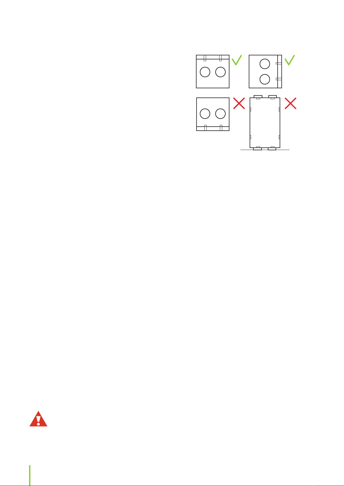
Electrical duct coils
• The heater is designed for insertion into stand-
ard spiral ducting and is fixed to the ducting with
screws.
• The air must flow through the heater in the direc-
tion indicated by the arrow on the side of the con-
nection box.
• The heater can be fitted in either horizontal or verti-
cal ducting. The heater may only be fitted in ducts
that are made of incombustible and heat-and-cold
resistant material. The connection box can be freely
placed facing upwards or sideways to a maximum
angle of 90°.
WARNING: Fitting with the connection box
facing downwards is NOT allowed.
• The distance from (to) the heater to (from) a duct
bend, valve, filter, etc, should correspond to at least
twice the duct diameter. Otherwise there is a risk
that the airflow through the heater will be uneven
which can cause activation of the overheating
cut-out.
• The duct heater may be insulated in accordance
with valid regulations for ventilation ducting.
However, the insulation must be incombustible. The
insulation must not cover the lid, since the rating
plate must be visible and the lid must be remova-
ble. Furthermore, the insulation must not cover any
heatsinks, nor the side of the connection box where
the SCR’s (Triac’s) are mounted.
• The duct heater must be accessible for replacement
and inspection.
• The distance from the heater metal casing to any
wood or other combustible material must NOT be
less than 30 mm.
• Install the duct sensor TE10 (delivered with the
heater) in the duct after the heater, if the heater is
mounted in the supply air duct. Or if the heater is
mounted in the outside air duct, install the temper-

12
ature sensor (TE01) before the heater in the outside
air duct and connect the sensor(s) to the MD con-
trol circuit board..
NOTE: We recommend installing a safety
switch for the electric heater.
Installing ventilation unit ceiling installa-
tion plate (OPTIONAL)
NOTE: Ceiling installation plate is separately
sold extra equipment available for ventilation
unit models Pinion, Pingvin, Pingvin XL and
Pandion.
Before attaching the ceiling installation plate
• Make sure that the ceiling is even so that the plate
will be stable and straight after it has been installed.
• The gap between the plate and the back wall
should be at least10 mm (recommendation) and at
least 15 mm between the plate and the side walls.
• Consider the height level of the final ceiling surface
material. The top of the ceiling installation plate can
be max 15 mm above the inner ceiling level.
To attach the ceiling installation plate,
1. Prepare holes in the ceiling for the ventilation
ducts.
2. Attach the plate on the ceiling using screws that
are suitable for the ceiling material.
3. Seal the ceiling installation plate against the ceil-
ing’s vapor barrier using for example duct tape.
4. Attach the ducts to the ceiling installation plate
with rivets.
Make sure there are no gaps between the insula-
tion and the ducts.
5. Consider the unit’s weight when screwing the
plate to the ceiling. The ceiling installation plate
must be absolutely rigid. Weights for all units are
found in the technical table in the end of this
instruction.
Installing geo-cooling equipment
If a geothermal heat pump is in use, the cold brine in
the ground loop can be used in the summertime to
cool the incoming air. The system can be implemented
in two ways: the solution can be circulated through
the geothermal pump (option 1) or a separate pump
can be used (option 2). The cooling coil can be either
built in the ventilation unit or it can be a duct coil,
depending on the model. A duct coil is mounted
in the supply air duct after the ventilation device.
Standard ventilation unit delivery is according to
option 2.
Detailed principal charts are found at the end of this
manual.
Option 1:
A geothermal heat pump is used for circulating brine
also in the supply air coil.
The delivery includes
• a relay for starting up the brine pump. The relay is
situated on the unit motherboard, connection DO3.
• a 3-way control valve (Termomix D32S) needed for
cooling and
• the actuator (Belimo NRYD24-SR-W + installation
set MS-NRE).
Temperature is controlled using the ventilation unit’s
own automatic control. The ventilation unit controls
the geothermal heat pump and the 3-way valve.
Installation:
1. Mount the cooling coil horizontally in the supply
air duct (in case of a duct coil).
2. Isolate a separate loop for the cooling coil.
Don’t forget the one-way valve. Follow the princi-
pal chart at the end of this manual.
3. Connect the condensate water outlet.
4. Install the 3-way valve and the actuator in the
ground collector’s piping. The actuator will con-
trol the brine flow to the cooling coil as needed.
Be sure to isolate the pipes carefully with vapour
proof insulation to prevent condensation on the
outside of the pipes in warm and semi-warm
spaces.
13
EN
Installation instructions
The heat pump will not be started up for ventilation
cooling.
Installation:
1. Mount the cooling coil in the supply air duct (in
case of a duct coil).
2. Connect the condensate water outlet.
3. Build a separate pump group with valve and
actuator for circulating cool brine adjacent to the
ventilation unit cooling coil. Be sure to isolate the
pipes carefully with vapour proof insulation to
prevent condensation on the outside of the pipes
in warm and semi-warm spaces.
Follow the principal chart at the end of this
manual.
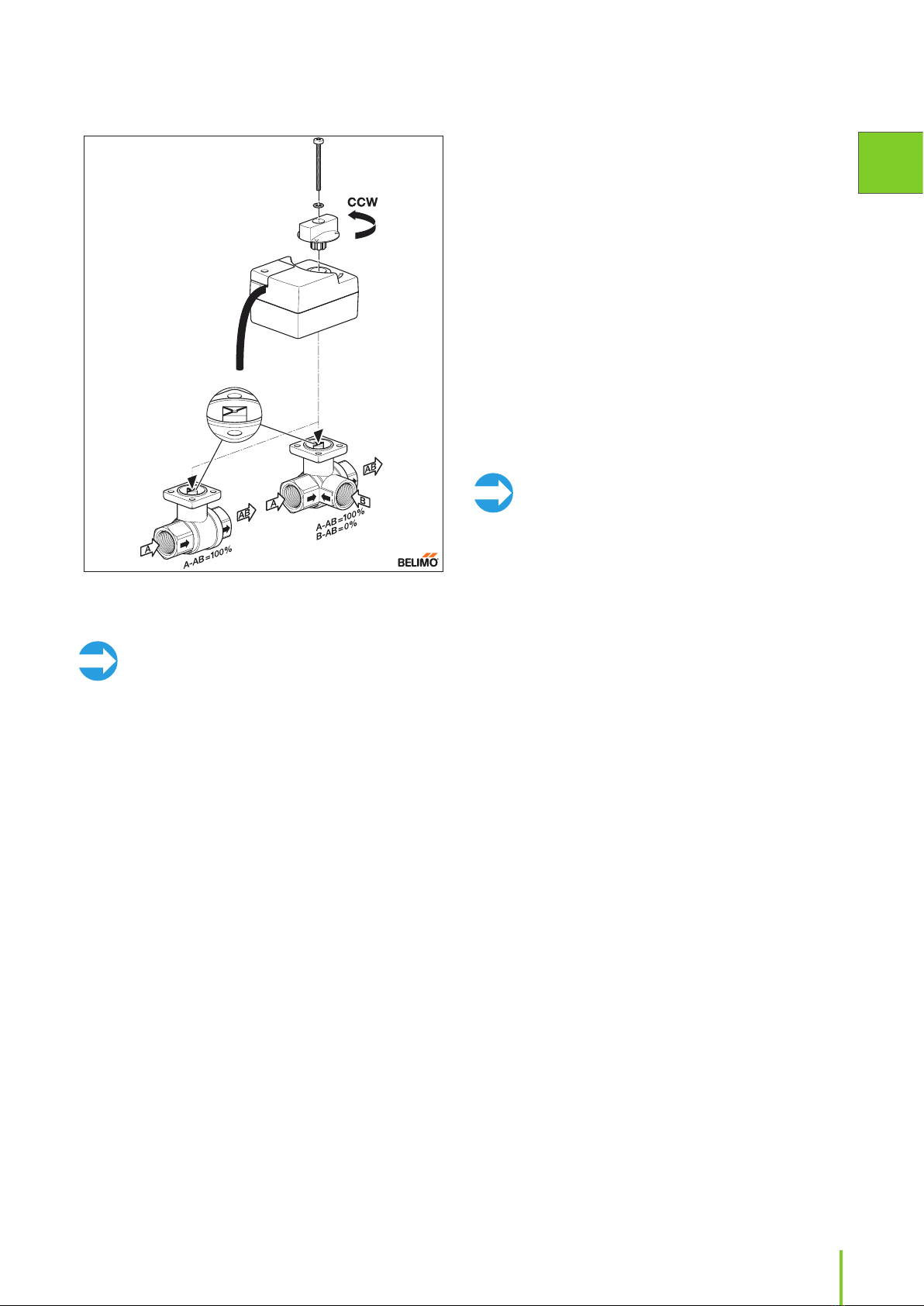
NOTE: The valve and actuator must be in the
same position when connected. When the
valve is in open position, the actuator is
turned counter-clockwise before connecting,
and when the valve is closed, the actuator is
turned cw before connecting. The Figure 1
shows the valve and markings on valve spin-
dle in valve open (cooling/heating on max)
position.
4. Prepare / connect wiring between the ventilation
unit, the geothermal pump and the actuator, as
shown in the connection diagram at the end of
this manual.
Installing CHG geothermal pre-heating /
pre-cooling equipment
A geothermal pre-heating / pre-cooling coil for
improving the system energy efficiency can be
installed in the ventilation system. A duct coil is always
used when a hydronic pre-heating coil is needed. The
coil is mounted in the outdoor air duct before the ven-
tilation unit. The duct or the coil must have a filter to
keep dirt out of the coil.
To avoid freezing the coil, the brine used in the coil
system must meet the local rated temperature value.
For example in Helsinki, the brine must still be func-
tional at -26°C whereas in Lapland the temperature
value is -38°C.
It is also possible to use earth to air heat exhangers
(Earth tubes) for pre-heating or pre-cooling. The earth
tube must be combined with a normal outside air
duct and a damper that switches the outside air flow
between the earth tube and the normal outside air
duct depending on the actual need for pre-cooling
Figure 1. Valve and actuator open counter-clockwise and close clock-
wise. Picture shows valve and actuator in the fully open position. Also
shown is the allowed direction of the liquid flow.
NOTE: The valve and actuator must be in the
same position when connected. When the
valve is in open position, the actuator is
turned counter-clockwise before connecting,
and when the valve is closed, the actuator is
turned cw before connecting. The Figure 1
shows the valve and markings on valve spin-
dle in valve open (cooling/heating on max)
position.
5. Prepare / connect wiring between the ventilation
unit, the geothermal pump and the actuator.
Option 2:
A separate pump is used for circulating brine in the
supply air coil.
The delivery includes
• a relay for starting up the circulation pump for the
ventilation unit’s cooling coil. The relay is situated
on the unit motherboard, connection DO3.
• a 3-way control valve (Belimo R3..) needed for cool-
ing and
• the actuator (Belimo TR24-SR).
Temperature is controlled using the ventilation unit’s
own automatic control. The ventilation unit controls
the circulation pump and the 3-way valve.

14
and pre-heating. The damper can be controlled from
the same relay that controls the circulation pump for
the hydronic pre-cooler/heater.
The CHG pre-heating / pre-cooling system can be built
as a separate system (option 1) or as a part of the geo-
thermal heat system (option 2).
Detailed principal charts are found at the end of the
manual.
Option 1:
A ground loop is built for the pre-heating/cooling coil.
To avoid freezing of the system, brine in the loop must
meet the local rated temperature value. The ventila-
tion unit automatic control regulates the system’s tem-
perature. The ventilation unit controls the circulation
pump and the 3-way valve.
Installation:
1. Mount the cooling/heating coil in the outside air
duct.
2. Connect the condensate water outlet.
3. Build a separate pump group for circulating cool
brine adjacent to the ventilation unit cooling/
heating coil. Be sure to isolate the pipes carefully
with vapour proof insulation to prevent conden-
sation on the outside of the pipes in warm and
semi-warm spaces.
4. Prepare / connect wiring between the ventilation
unit, the circulation pump and the actuator.
5. Install and connect the outside air temperature
sensor (TE01) in the outside air duct before the
duct coil. Consult the electrical connection dia-
grams at the end of this manual.
Option 2:
A separate loop is isolated from the geothermal pump
brine loop for the cooling coil. To avoid freezing the
coil, brine in the loop must meet the local rated tem-
perature value. In addition to this, a heat exchanger is
installed in the coil system to ensure the functionality
of the geothermal pump. For the pre-heating / pre-
cooling coil to yield any benefits, there must be some
flow in the collector ground loop of the geothermal
pump. Temperature is controlled using the ventilation
unit’s own automatic control. The ventilation unit con-
trols the circulation pump and the 3-way valve.
Installation:
1. Mount the cooling / heating coil in the outside air
duct.
2. Connect the condensate water outlet.
3. Build a separate pump group for circulating cool
brine adjacent to the ventilation unit cooling coil.
Be sure to isolate the pipes carefully with vapour
proof insulation to prevent condensation on the
outside of the pipes in warm and semi-warm
spaces.
4. A heat exchanger is installed in the coil system.
5. Install and connect the outside air temperature
sensor (TE01) in the outside air duct before the
duct coil. Consult the electrical connection dia-
grams at the end of this manual.
6. Prepare / connect wiring between the ventilation
unit, the geothermal pump and the actuator.
Requirements and preparations
for electrical connections
NOTE: Only an authorized electrician is
allowed to perform electrical work on the
ventilation units.
Refer to the electrical drawings at the back of this
manual.
Preparatory electrical work
Before you start the installation, make sure that:
• Appropriate power supply is available for the venti-
lation unit.
• Higher than 30mA fault current is provided.
Because of this, no other electrical appliances
should be plugged into the same outlet.
• An internet connection is provided, if the user
wants to access the eAir panel network interface.
• Wall mount of the eAir panel is installed on a wall
junction box. Do not keep the eAir wall mounting
bracket uninstalled while using the eAir panel. If
You accidentally contact the circuit board behind
the wall mounting bracket with your hand or
any conductive object, you can damage the wall
mounting bracket.
• Cabling between the unit and the control panel
wall mount. The cable must run inside a protective
conduit of at least Ø 20 mm. The cable included in
the basic delivery is 10 m. Optionally, a 30 m cable is
available. The cable heads are type RJ4P4C.

15
EN
Installation instructions
External sensors:
Some external sensors might need to be installed
depending on model of ventilation unit.
• The sensor element for duct mounted temperature,
RH and CO2 sensors is to be mounted inside the
duct. Most temperature sensors are supplied with
a ready made 5 m long cable. RH and CO2 sensors
need wiring on site.
• The place for the sensor is chosen according to
the unit of measurement that is to be measured.
Consult the control diagram at the end of this
manual. The placement in the duct is chosen at a
straight segment, at least 2x the duct Ø before and
after any duct coil, bends or fittings.
• A suitable hole for the sensor and a rubber grom-
met is drilled in the duct.
• Sensors attached to a cable is pushed trough the
rubber grommet so that the sensor element is a few
centimetres inside the duct. The rubber grommet
must be air tight, and tight enough that the sensor
cable cannot slip trough by itself. A cable tie is rec-
ommended to lock the sensor in place.
• Sensors with rigid pipe type sensor elements,
are mounted trough an adjustable flange, that is
mounted to the duct. The sensor element is pushed
trough the flange and locked in place with a screw
at a suitable depth.
• Electrical connections are done according to the
electrical schematics at the end of the manual.
Preparing eAir control panel wall mounting
bracket
The eAir control panel needs to be installed on a wall
junction box. One ventilation unit can be controlled
with the maximum of 2 panels. The panels can have
their own wall mounting brackets, or both panels can
be linked to the same wall mounting bracket. If the
panels have a shared holder, the other panel needs
a separate micro USB charger (not supplied by Ensto
Enervent).
Commissioning two control panels with their own
wall mounting brackets
If the ventilation unit is controlled with two control
panels with their own wall mounting brackets, the
panels must be given different addresses. The address
is chosen on the controller card on the back of the wall
mounting bracket. One of the wall mounting brackets
will get the address“1” and the other the address“2”.
We recommend that the address is marked both on
the wall mounting bracket and on the control panel,
so the residents know which panel belongs in which
wall mounting bracket.
Commissioning two control panels with shared
wall mounting bracket
If the ventilation unit is controlled with two control
panels with a shared wall mounting bracket, the
additional panel must be linked to the wall mounting
bracket. To do that, slide the DIP sliding switch“2”
down and up again. Check the electrical connection
diagram on page 85 . The linking mode is activated
if a yellow LED light starts flashing on the controller
card. The linking mode is active for 10 minutes.
Momentarily place the eAir operating panel in the wall
mounting bracket, for the panel to start up. The panel
will show that it is trying to connect to the network.
Press Re-connect the radio > Reset. Now the control
panel will connect to the wall mounting bracket.
Connecting room temperature sensor to wall
mounting bracket (additional equipment)
In order to run the unit on room temperature regula-
tion, a room temperature sensor must be connected.
The room temperature sensor is connected to the con-
troller card on the back of the wall mounting bracket.
If you install two wall mounting brackets with room
temperature sensor, the sensor TE20 is connected to
the wall mounting bracket“1” and TE21 connected to
the wall mounting bracket“2”.
NOTE: You need to go through the set-up
wizard only in one of the panels. Connect
the power to the other panel when you are
ready with the wizard. The panel will fetch the
updated data from the motherboard.

16
The functions and accessories listed in the following table may need external wiring or connecting to
function:
Location on MD
controller card Voltage/current Cable
(example) Wiring outside
AHU
AI NTC
TE20 /TE21 Room temperature
sensor Connector on
eAir operating
panel wall holder
circuit board
3,3VDC KLM 2X0.8 Yes
TE01 Outside air temperature X1 3,3VDC Quick connector
5m cable sup-
plied with AHU
Yes, if preheater/
preecooler (CHG)
TE10 Supply air temperature X3 3,3VDC Quick connector
5m cable sup-
plied with AHU
Yes, if duct heater/
cooler coil
TE62 Supply coil liquid pipe
(MDX) X5 3,3VDC Quick connector
5m cable sup-
plied with AHU
Yes, if DX duct coil
TE62 (MDX)
TE45 Heating coil return water
temperature X12 3,3VDC Quick connector
5m cable sup-
plied with AHU
Yes, if duct heater
coil
Digital outputs DO Potential free contact
ON/OFF Control for heating DO2 Max 250VAC/50VDC
8A/2A inductive load MMJ 3x1,5 Yes, if hydronic
heating
ON/OFF Control for cooling
/ ON/OFF control for heating
(MDX)
DO3 Max 250VAC/50VDC
8A/2A inductive load MMJ 3x1,5 Yes, except HP and
CO
ON/OFF Control for dampers DO5 Max 250VAC/50VDC
8A/2A inductive load MMJ 3x1,5 Yes
ON/OFF Control for preheating
/ ON/OFF Control for precool-
ing (CHG) / ON/OFF Control for
heating circulating pump (Aqua
KIW)
DO6 Max 250VAC/50VDC
8A/2A inductive load MMJ 3x1,5 Yes, except Twin
Tropic or built in
preheater coil
Timer controlled relay / ON/OFF
Control for circulating pump
PU80 (Aqua) / ON/OFF control
for extract air cooling (TCG)
DO7 Max 250VAC/50VDC
8A/2A inductive load MMJ 3x1,5 Yes
A/AB alarm output NO DO8 Max 250VAC/50VDC
8A/2A inductive load KLM 2x0.8 Yes
Analog inputs AI
%RH1 AI1 (user
configurable) 0-10VDC KLM 4x0.8 Yes
%RH2 / Boiler temperature TE80
(Aqua) AI2 (user
configurable) 0-10VDC KLM 4x0.8 Yes
Free / PDE10 supply air duct
pressure AI3 (user
configurable) 0-10VDC KLM 4x0.8 Yes
Free / PDE30 extract air duct
pressure AI4 (user
configurable) 0-10VDC KLM 4x0.8 Yes
CO2/1 AI5 (user
configurable) 0-10VDC KLM 4x0.8 Yes
CO2/2 AI6 (user
configurable) 0-10VDC KLM 4x0.8 Yes
RH10 Supply air relative humid-
ity sensor (Dehum/Twin Tropic/
TCG)
AI11 (sw
configurable) 0-10VDC KLM 4x0.8 Yes, if duct coil
TE10 Supply air temperature
(Dehum/Twin Tropic/TCG) AI12 (sw
configurable) 0-10VDC KLM 4x0.8 Yes, if duct coil

17
EN
Installation instructions
Location on MD
controller card Voltage/current Cable
(example) Wiring outside
AHU
Free AI13 (sw
configurable) 0-10VDC KLM 4x0.8
Free AI14 (sw
configurable) 0-10VDC KLM 4x0.8
Free AI15 (sw
configurable) 0-10VDC KLM 4x0.8
Free AI16 (sw
configurable) 0-10VDC KLM 4x0.8
Analog Outputs AO
Control voltage for cooling /
Control voltage for additional
after heater (MDX-E/HP-E/HP-W)
AO3 0-10VDC 10mA KLM 2x0.8 Yes, except built in
heater
Control voltage for heating /
Control voltage for compressor
power (MDX/HP)
AO5 0-10VDC 10mA KLM 2x0.8 Yes, if MDX or
hydronic heating
Control voltage for preheater
/ Control voltage for precooler
(CHG) / Control voltage for HRW
#2 (Twin Tropic)
AO6 0-10VDC 10mA KLM 2x0.8 Yes, CHG
Control voltage for extract air
preheater (HP) / Control voltage
for extract air dehumidification
(TCG) / Control voltage for HRC
defrosting (WGHR)
AO7 0-10VDC 10mA KLM 2x0.8 Yes, if duct heater
Control voltage for hot water
production AO8 0-10VDC 10mA KLM 2x0.8 Yes
Digital inputs DI Connected to poten-
tial free NO contact
Emergency stop DI1 (fixed) 24VDC KLM 2x0.8 Yes
PDS10 supply fan pressure
switch / Defrosting indication
(MDX/HP)
DI2 (user
configurable) 24VDC KLM 2x0.8 Yes, MDX
Additional time (office mode
only) DI3 (user
configurable) 24VDC KLM 2x0.8 Yes
Manual boost DI4 (user
configurable) 24VDC KLM 2x0.8 Yes
Away mode DI5 (user
configurable) 24VDC KLM 2x0.8 Yes
Overpressure DI6 (user
configurable) 24VDC KLM 2x0.8 Yes
Central vacuum cleaner
indication DI7 (user
configurable) 24VDC KLM 2x0.8 Yes
Cooker hood indication DI8 (user
configurable) 24VDC KLM 2x0.8 Yes
Electrical after heater alarm /
Compressor fault (MDX/HP) DI10 (fixed) 24VDC KLM 2x0.8 Yes, if MDX
Miscellaneous connections
Operating panel connectors X27, X28 10m cable sup-
plied with AHU Yes
Modbus-RTU X26 Instrumentation
cable 2x2x0.5 Yes
Ethernet X19 Cat5 Yes
O3 Ozone sensor (ION) Connector 11 on
ICEA2000A unit 0-10VDC KLM 4x0.8 Yes
For more information on electrical connections, see the control and connection diagrams at the end of this
manual.

18
The ventilation unit can also be connected via
Modbus, connector X26. Specification of Modbus:
• Modbus address 1 (default)
• Communication standard RS485
• Modbus traffic via Modbus connector X26 of con-
troller card
• Speed 9600, 19200 or 115200 bps
• 8 bit
• No parity or parity
The order of Freeway connector’s pins is marked on
the controller card.
X1X2X3X4X5
X7
X12
X19
DO6DO5DO4DO3
DO1 DO2
X28X27
X26
JP5
JP2
MD EMOKORTTI
Ha
Mu
Ru
TULO
X9
X10
DI11
GND
A01
Ethernet
MODBUS-RTU
1234
X6
DO8DO7
AO8
A B GND
+12V
Modbus registers are available on Ensto Enervent
webpage www.enervent.
WARNING: Do not connect the external bus
to the motherboard before the bus is pro-
grammed and compatible with the unit con-
trol parameters.
Installation
NOTE: Before you install the ventilation unit,
make sure there are no foreign objects in the
ventilation unit and duct system.
• Refer to the model-specific dimensional drawings in
the back of this manual for your specific ventilation
unit type.
• Make sure to check the order of duct connections
to avoid crossed connections.
• Do not start the ventilation unit although it is
installed until the building is taken into use.
• If the ventilation unit is started too early, the ven-
tilation system will be contaminated by building
dust.
• The ventilation unit duct connections are the same
size as the duct. Use a circular duct fitting to con-
nect the unit to the duct.
• Remember to insulate the duct all the way to the
unit casing.
Additional materials needed for
installation
Material Description of use
Screws For hanging the rear attachment
bracket and ventilation unit on the
wall (if applicable). Select the screws
according to the wall material.
Sheet metal
screws For attaching the rear attachment
bracket onto the ventilation unit.
Wall junction
box For installing eAir wall mount.
Cables As specified in chapter Preparatory
electrical work
Duct tape For sealing.
Insulation
sheets (soft
foamed plastic)
For preventing structure-borne
noise.
Insulation mate-
rial (foamed
plastic and/or
wool, depend-
ing on where
the unit will be
installed)
For heat and sound insulation.
Rivets For attaching the ventilation ducts
onto the unit.
Spirit level For making sure that the unit is level.
Water pipe For connecting duct coils and for
disposing of condensate water.
Watertrap For condensate water drain.
Reducing fit-
tings for duct
connections
For fitting the ducts in the ventila-
tion system.
NOTE: Always use reducing fittings,
if necessary.
Dampers To keep cold air out.
Silencers To reduce possible noise.
Suitable grom-
mets for duct
mounted
sensors
For mounting sensors in the ducts.
Shut-off valves To facilitate servicing of unit.
Hydronic bal-
ancing valves To adjust for proper water flow.

19
EN
Installation instructions
• Make sure the ventilation ducts are insulated
according to the instructions in Insulating venti-
lation ducts chapter
• Make the applicable electrical and plumbing
connections according to the electrical and prin-
cipal diagram at the end of this manual.
6b. For model Pinion:
• Lift the unit on the wall at the desired height and
attach it to the wall by the upper mounting lugs.
7. Connect the ducts to the duct connections on the
unit.
8. Connect the drain for disposing of condensate
water.
For more information, see chapter Draining con-
densate water.
9. Make sure you have insulated the ducts all the
way to the ventilation unit frame.
10. Make the applicable electrical and plumbing con-
nections according to the electrical and principal
diagram at the end of this manual.
Ceiling installation
Ceiling installation for models Pingvin and
Pandion
Dimensional drawings for each of the models can be
found at the end of this manual.
1. Install the supplied duct couplings and insulation
rings on top of the unit.
2. Unscrew the cover of the electrical cabinet.
Prepare the cable lead-ins on unit for the cables
coming through the ceiling.
Leave the electrical cabinet cover open.
3. Guide the unit power cable to run in front of the
hook to keep the cables from squashing between
the unit and the ceiling installation plate.
NOTE: Remove the heat exchanger before
you lift the unit. This will make the unit much
lighter to handle. Remember also to remove
or secure the doors so that they won’t open
during lifting.
Installing models Pinion, Pingvin,
Pingvin XL, Pandion, Pelican,
Pegasos, Pegasos Twin Tropic and
Pallas
Wall installation
For models Pinion, Pingvin, Pingvin XL and Pandion
1. Prepare the holes in the wall.
2. Bring in the ducts through the cross cut in the
vapor barrier to the height to which the unit will
be mounted.
3. Seal the vapor barrier pass-through using for
example duct tape.
4. Install an insulating plate at the back of the ven-
tilation unit or otherwise prevent the structure-
borne noise. Soft foamed plastic sheets are rec-
ommended (not included in the delivery).
5. Install an extra layer of insulation outside the ven-
tilation unit (for example foamed plastic), if the
unit is installed with its side against exterior wall
or if there is any other reason to suspect that the
outside of the unit will condesate. Condensation
risk is present in areas where the climate is cold.
6. Installation varies for different models:
6a. For models Pingvin, Pingvin XL and
Pandion:
• Install the rear attachment bracket at the desired
height.
• Lift the unit on the bracket.
NOTE: Remove the heat exchanger before
you lift the unit. This will make the unit much
lighter to handle. Remember also to remove
or secure the doors so that they won’t open
during lifting.
• Attach the unit to the wall by the upper mount-
ing lugs.
• Don´t forget the rubber bushings for the fasten-
ing screws. (Pingvin and Pandion only).
• Attach the rear attachment bracket to the unit’s
base using sheet metal screws.
NOTE FOR PINGVIN: It is essential for the
proper disposal of condensate water that a
Pingvin unit is installed slightly tilted back-
wards. This must be verified using a spirit
level.

20
NOTE: Make sure to leave the cables loose
in case the unit needs to be taken down for
some reason.
NOTE FOR PINGVIN: It is essential for the
proper disposal of condensate water that a
Pingvin unit is installed slightly tilted back-
wards. The Pingvin unit is automatically
installed tilted in the ceiling installation plate.
Taking down ceiling installed unit
WARNING: Make sure you are holding the
unit in its place when opening the locking
plates. When the locking plates are opened,
the unit’s back side will disengage from the
ceiling plate. Make sure you have enough
space under the unit for it to swing down.
1. Disconnect the power supply.
2. Open the security screws.
3. Open the electrical cabinet and disconnect the
cables coming from the ceiling.
4. Holding the unit securely in its place, twist both of
the locking plates open (towards yourself) using
a screwdriver.
5. Lift down the unit.
Ceiling installation for models Pinion and
Pingvin XL
Before installing the ventilation unit, make sure that
the insulation rings for the duct connections and the
plastic spacers for the attaching screws are in place.
Pingvin XL is attached to the ceiling installation plate
from the inside of the unit.
Pinion ventilation unit is attached to the ceiling
installation plate with two screws under the unit.
1. Pinion: Remove the fans and heat exchanger.
Pingvin XL: Remove the heat exchanger, extract
fan and extract filter
To make the unit lighter to handle, we recom-
mend that you remove these components before
lifting the unit up to hang from the attaching
hook.
2. Attach the ventilation unit onto the ceiling plate
using the screws included in the delivery.
3. Tighten the screws in turns so that the unit sets in
place evenly.
The tightening torque is max 5 Nm.
4. Make sure there is enough space underneath the
ceiling plate to fit the unit.
5. Lift the unit up.
6. Hook the unit to the front side of ceiling installa-
tion plate.
7. Connect the cable(s) coming through the ceiling
plate to the electrical enclosure box.
8. Make sure the unit is hanging straight, directly
in the middle of the ceiling plate.
9. Push the base of the unit upwards until it locks
onto the ceiling plate.
10. Secure the unit in place by tightening the two
security screws on both sides of the ceiling plate.
+ =
CLICK
The installation is secure even with just the locking
system of the ceiling plate. The security screws are an
added security measure.
11. Put the heat exchanger back in the unit and close
the electrical cabinet door. Put the doors back if
you removed them before the lifting.
12. Make the applicable electrical and plumbing
connections including the condensation drain
according to the electrical and principal diagram
at the end of this manual.
Other manuals for Enervent eAir
2
Table of contents
Popular Remote Control manuals by other brands


Sony
Sony RM-P352 Programming guide

Genius
Genius AMIGOLD TX4 868 instructions

Hobby King
Hobby King HK-6DF user manual

Panasonic
Panasonic CZ-RTC2 User functions guide

Panasonic
Panasonic CZ-RTC6BLW operating instructions

Rothenbuhler Engineering
Rothenbuhler Engineering REMOTE FIRING DEVICE Operator's manual


