ENTELIGENT NMax M900A1 User manual
Enteligent NMax M900A1 Rapid Shutdown
Device (RSD) with Optimization
INSTALLATION MANUAL

Table of Contents
1. Important Safety Instructions...............................................................2
2. Package contents.................................................................................3
3. Overview...............................................................................................3
4. Installation............................................................................................4
i. Mounted on Standard module..........................................................5
ii. Connection.......................................................................................6
iii. Optional Heatsink Grounding...........................................................6
5. Connector Types..................................................................................8
6. Technical Specifications......................................................................9
1Enteligent NMax M900A1 Installation Manual Version 1.0

2Enteligent NMax M900A1 Installation Manual Version 1.0
1. Important safety instructions
This manual contains important instructions for Enteligent NMax M900A1
RSD with Optimization that shall be followed during installation and
maintenance.
Install the product in strict accordance with the installation manual.
Risk of electric shock. Do not disassemble,or repair the unit, no user
serviceable parts inside. Refer servicing to qualified service personnel.
Before installing or using the Enteligent NMax M900A1,please read all
instructions and warning markings on the Enteligent NMax M900A1
product, appropriate sections of your inverter manual,photovoltaic (PV)
module installation manual,and other available safety guides.
Only certified electricians are allowed to install,maintain,troubleshoot,
and replace the optimizer.Enteligent NMax M900A1 does not assume
liability for loss or damage resulting from improper handling,installation,
or misuse of products.
Before making connections to Enteligent NMax M900A1,ensure the
optimizer is not damaged.Check existing cables and connectors, ensuring
they are in good condition and appropriate in rating. Do not operate the
Enteligent NMax M900A1 with damaged or substandard wiring or
connectors.Enteligent NMax M900A1 must be mounted on the high end
of the PV module frame,and in any case above ground.
Do not connect or disconnect under load. Turning off the Inverter and/or
the Enteligent NMax M900A1 may not reduce this risk.Internal capacitors
within the inverter can remain charged for several minutes after disconnect-
-ing all power sources. Verify capacitors have discharged by measuring
voltage across inverter terminals prior to disconnecting wiring if service is
required.
Wait 30 seconds after rapid shutdown activation before disconnecting DC
cables or turning off DC disconnect.
To allow proper heat dissipation and installation,maintain appropriate
clearances between the optimizer and other objects.
Before maintenance, power off the optimizer and strictly comply with the
safety precautions in this document and associated documents to operate
the optimizer.
Failure to adhere to these instructions may result in injury or death, damage
to the system, or voiding the factory warranty.

3Enteligent NMax M900A1 Installation Manual Version 1.0
2. Package contents
3. Overview
Power optimization
Manual
Heatsink grounding bracket and tooth washer
Bracket clip mount to module frame without tools.
Enteligent NMax M900A1 inputs connect to module
junction box,outputs are connected in series to form a string.
No additional grounding required.
The Enteligent NMax RSD with Optimization
optimizer is a DC-DC converter installed on the back of
solar panels in a solar system.It tracks the maximum power
point (MPP) of each solar panel to improve energy yield of the
whole solar system.It is also a rapid shutdown device (RSD)
complied with NEC 2017 and NEC 2020 article 690.12.
Solar PV
Module
Solar PV
Module
Solar PV
Module
Solar PV
Module
M900A1
M900A1
M900A1
M900A1
PV Solar
Sting
Inverter
+
+
+
+
-
-
-
-
4Enteligent NMax M900A1 Installation Manual Version 1.0
4. Installation
i) Mounted on standard PV module
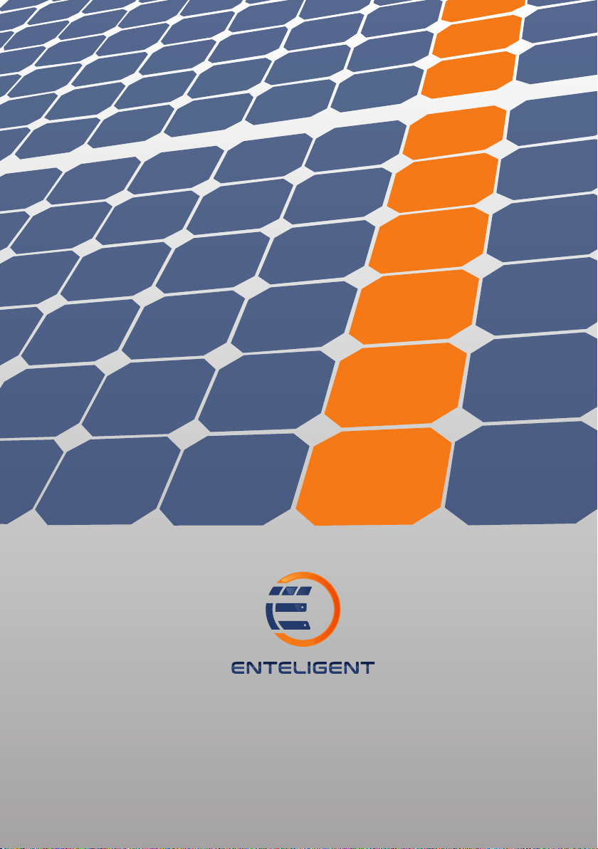
M900A1 cable glands must not be facing up.
M900A1 mounting is recommended on the
upper left as shown, but can be placed on
upper right if needed (due to racking
constraints, etc).
Allow clearance between PV module
and mounting surface for air circulation
around the Enteligent NMax M900A1.
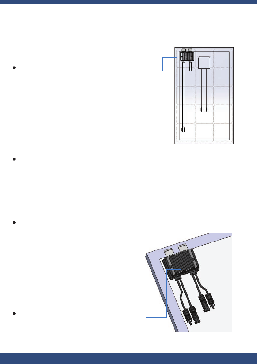
Recommended orientation of the Enteligent
NMax M900A1 on module frame after mounted
as shown (heatsink face outwards).
5Enteligent NMax M900A1 Installation Manual Version 1.0
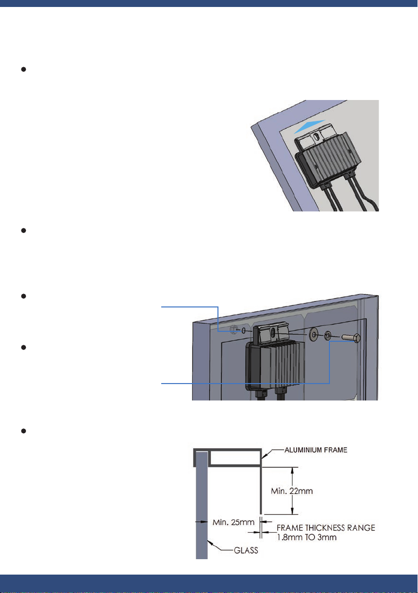
Use bracket clip mount to module frame, just simply insert the clip up to the
end into the frame in the desired location.
Other than using the bracket clip,the Enteligent NMax M900A1 can also be
mounted on the module frame by screw, washers and nut (parts do not include
in product) if there is mounting hole on the module frame.
Module Frame Requirement for mounting the Enteligent NMax M900A1
Hole on module frame
(around 9mm diameter)
M8 x min.30mm screw,
spring washer, plain washer
and nut. Washer outside
diameter do not larger than
22mm
6Enteligent NMax M900A1 Installation Manual Version 1.0
ii) Optional Heatsink Grounding
The M900A1 headsink is in electrical isolation. The
heatsink can be optionally ground to the metallic frame
of the PV module through attachment of the optional
grounding bracket. Grounding of all exposed metal,
such as the heatsink, may be required for regulatory
compliance or system configuration architecture.
Once the assembly is installed to the PV module frame, drill a 4mm diameter
hole through the metal PV module frame in line with the ground hole in the
grounding bracket, as per the diagram below. Secure the bracket with a M3.5
self-tapping screw and a M3.5 tooth washer or equivalents.Note that the self
tapping screw and tooth washer are not provided.
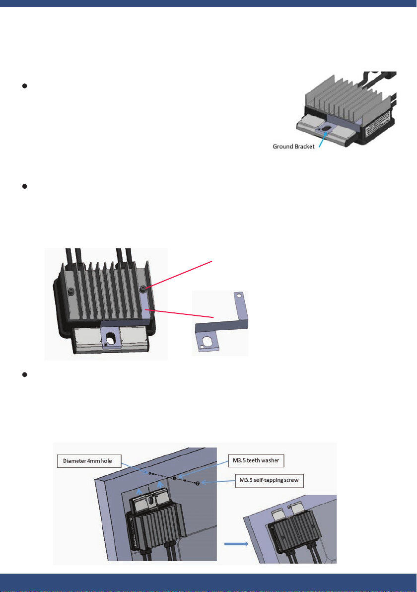
To fasten the grounding bracket to the heatsink,remove the existing M4 screw
as shown on the diagram below,affix the ground bracket, and replace the M4
screw with the enclosed tooth washer.
Affix the bracket with existing M4
screw and add the provided tooth
washer
Ground bracket

7Enteligent NMax M900A1 Installation Manual Version 1.0
iii) Connection
port definition
out+ -out in in+ -
Each the Enteligent NMax M900A1 must have PV module(s) connected to its inputs
before connecting the outputs of M900A1 units in series or in parallel.
To disconnect the Enteligent NMax M900A1 from module(s), disconnect the
M900A1 outputs from the string before disconnecting the M900A1 inputs from
the module(s) junction box.
Note: Do not connect or disconnect under load.It is always to connect module
to the Enteligent NMax M900A1 inputs before connecting to outputs.
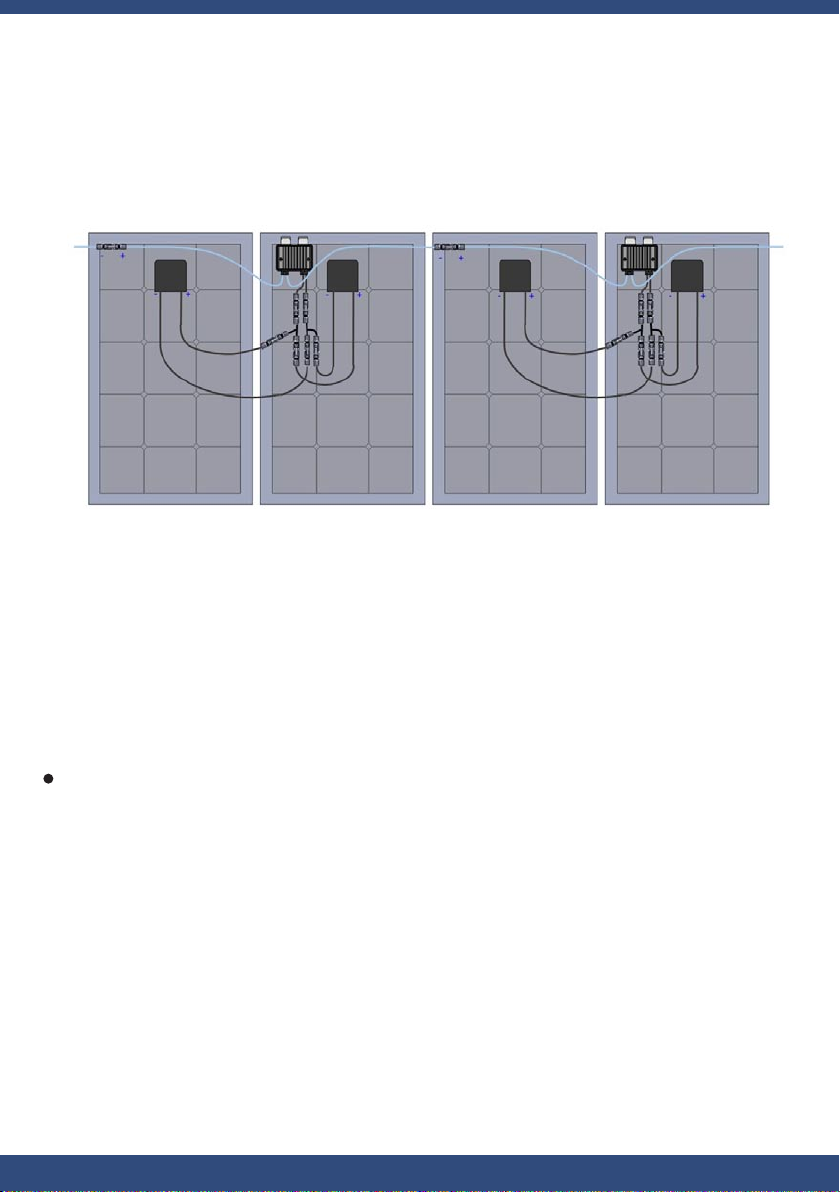
Panel Max Rating: 80Voc, 12.5A max, 900W max
1. the Enteligent NMax M900A1 in series
Standard modules can be equipped with the Enteligent NMax M900A1
add-on units as shown below

8Enteligent NMax M900A1 Installation Manual Version 1.0
2. Enteligent NMax M900A1 in parallel
3. Panels in series into the Enteligent NMax M900A1
Panel Max Rating: 40Voc, 12.5A max, 450W max
Panel Max Rating: 80Voc, 10A max,800W max
9Enteligent NMax M900A1 Installation Manual Version 1.0
4. Panels in parallel into the Enteligent NMax M900A1
5. Connector Types
With add-on units, failing to follow the sequence of installation steps may result
in the Enteligent NMax M900A1 damage and not covered under warranty.
PV modules use a variety of output connectors. Enteligent NMax RSDs come
with several options of supporting connectors by M900A1 module number as
listed in Section 6: Specifications. Enteligent’s warranty will not apply to issues
relating to use of non-identical connector types without first verifying
compatibility between Enteligent NMax RSDs and PV modules or other devices.
CAUTION: Installation of Enteligent NMax RSDs without first ensuring its
compatibility with the PV module connectors may be unsafe and could cause
functionality issues such as ground faults, resulting in system shutdown.
Panel Max Rating: 80Voc, 6.25A max, 450W max

10Enteligent NMax M900A1 Installation Manual Version 1.0
6. Technical Specification
and others
No.
Enteligent NMax M900A1 RSD
with Optimization
Model Number by Connector Type
M900A1-S4
M900A1-M4
BizLink S418 (MC4 Compatible)
Staubli MC4

11Enteligent NMax M900A1 Installation Manual Version 1.0
Marking Description
Electric Shock Warning
Hot Surface Warning

www.enteligent.com
Table of contents
Popular Accessories manuals by other brands


Chef's Choice
Chef's Choice 220 instruction manual

RecorderGear
RecorderGear PB500 user manual

Multitech
Multitech RBS301-DWS-US user guide

Alfalaval
Alfalaval Rotacheck instruction manual

C.P. Electronics
C.P. Electronics EBMINT Product guide

Silvercrest
Silvercrest 43150 Assembly, operating and safety instructions