Impact Subsea ISA500 User manual

www.impactsubsea.com
Innovative Underwater Products
ISA500
Altitude, Pitch, Roll &
Heading Sensor
Installation & Operation
Manual
Revision: 1.7
Date: 15/01/2020
Impact Subsea Ltd
T. +44 (0) 1224 460 850
E. info@impactsubsea.co.uk
W. www.impactsubsea.com

Contents
1.0 Introduction.................................................................................................................................3
2.0 Specification................................................................................................................................4
2.1 Overview .........................................................................................................................4
2.2 Dimensions.......................................................................................................................4
2.2.1 Forward Looking Housing.....................................................................................4
2.2.2 Right Angle Housing..............................................................................................4
2.3 Acoustic, Heading, Attitude & Temperature....................................................................5
2.4 Communications, Power & Physical...............................................................................5
3.0 Installation .............................................................................................................................6
3.1 Electrical Installation.......................................................................................................6
3.1.1 Connector Pin Out................................................................................................6
3.1.2 Power....................................................................................................................7
3.1.3 Serial Interface.....................................................................................................7
3.1.4 RS232 Wiring.......................................................................................................7
3.1.5 RS485 Wiring.......................................................................................................8
3.1.6 Analogue Out and TTL Trigger............................................................................9
3.1.7 Establishing Communications............................................................................10
3.1.8 Connector Mating...............................................................................................10
3.1.9 Connector Cleaning............................................................................................11
3.2 Location...........................................................................................................................11
3.2.1 Acoustics (Altitude Measurement Performance)................................................11
3.2.2 Magnetic Disturbers (Heading Performance).....................................................11
3.2.3 Alignment with Vehicle (Pitch/Roll Accuracy)..................................................12
3.2.4 Heat Sources (Temperature Accuracy)...............................................................13
3.3 Mounting .......................................................................................................................13
4.0 Operation ..................................................................................................................................14
4.1 Use with seaView software............................................................................................14
4.2 Integration with systems................................................................................................15
4.3 Understanding advanced features..................................................................................15
5.0 Servicing....................................................................................................................................17
6.0 ASCII Output Strings ..............................................................................................................18
6.1 Altitude ..........................................................................................................................18
6.2 AHRS.............................................................................................................................24
7.0 Theory Of Operation.................................................................................................................26
7.1 Altitude - Basic Principles..............................................................................................26
7.2 The Sonar Equation........................................................................................................28
7.2.1 Source Level (SL)............................................................................................28
7.2.2 Transmission Loss (TL)....................................................................................29
7.2.3 Noise Level (NL)..............................................................................................29
7.2.4 Directional Index (DI)......................................................................................30
7.2.5 Detection Threshold (DT)................................................................................30
7.3 Heading, Pitch & Roll....................................................................................................31
7.4 Temperature....................................................................................................................31
8.0 Warranty....................................................................................................................................32
9.0 Technical Support .....................................................................................................................33

www.impactsubsea.com
Innovative Underwater Products
1.0 Introduction
The ISA500 provides exceptionally accurate and long range underwater distance
measurement capability. Optionally the ISA500 can also provide Heading, Pitch,
Roll and Temperature readings.
Designed to measure distance to the seabed (as an underwater Altimeter) the
ISA500 can also be used in a number of underwater applications where a distance
requires to be measured or monitored.
Utilising a broadband composite transducer and advanced digital signal processing
techniques; enables the ISA500 to achieve long range capability with a high degree
of accuracy and stability.
The availability of heading, pitch and roll provides the capability to clearly
understand the orientation of the unit at all times. This can also be used to
automatically correct slant range readings; providing a true altitude measurement if
required. Alternatively these sensor readings can be used for navigation purposes
of a ROV, AUV or other underwater item.
Housed in a compact titanium or lightweight acetal housing and available in
forward looking and right angle housing configurations; ensures that the ISA500 is
not only at the forefront of sensor technology, but is built to withstand the most
extreme underwater environments.
ISA500 (Forward Looking Titanium Housing) ISA500 (Right Angle Acetal Housing)
© Impact Subsea Ltd 3

www.impactsubsea.com
Innovative Underwater Products
2.0 Specification
2.1 Overview
ISA500 (Forward Looking Titanium Housing) ISA500 (Right Angle Acetal Housing)
2.2 Dimensions
2.2.1 Forward Looking Housing
2.2.2 Right Angle Housing
All dimensions are in mm.
© Impact Subsea Ltd 4

www.impactsubsea.com
Innovative Underwater Products
2.3 Acoustic, Heading, Attitude & Temperature
Acoustic Attitude
Frequency 500kHz Standard
(400 to 600kHz
Selectable)
Pitch Range ± 90°
Roll Range ± 180°
Range 0.1 to 120+m
(Maximum range dependant on
seabed type: Ranges in excess
of 175 meters are achievable
with a strong acoustic reflector)
Accuracy 0.2°
Resolution 1mm Resolution 0.1°
Beam Angle 6° conical at 500kHz Temperature
Signalling Monotonic Accuracy 0.5°
Pulse Length User Defined Resolution 0.1°
Heading
Accuracy ± 1°
Resolution 0.1°
2.4 Communications, Power & Physical
Communications & Power Physical
Digital RS232 & RS485 F/L: Weight (Air/Water)
R/A: Weight (Air/Water)
0.5 / 0.325kg (Titanium)
0.3 / 0.11kg (Acetal)
0.52 / 0.35kg (Titanium)
0.325 / 0.125kg (Acetal)
Protocol 300 to 115200
baud
Depth Rating 6,000 meters (Titanium)
1,000 meters (Acetal)
(11,000 meter option
available)
Analogue 0 to 5 V DC or
0 to 10V DC or
4-20mA
Temperature Operating: -10 to 40°
Storage: -20 to 50°
Data Continuous or on
demand
Connector Subconn MCBH8M-SS
fitted as standard
Data Rate Up to 10Hz
* 100% Tx power, 10Hz update rate
Input Voltage 9 to 36V DC
Power (No Altitude) 25mA @ 24V DC
Power (With
Altitude)
51mA @ 24V DC
*
© Impact Subsea Ltd 5

www.impactsubsea.com
Innovative Underwater Products
3.0 Installation
3.1 Electrical Installation
The ISA500 is fitted with a SubConn MCBH8M-SS connector as standard.
This will mate to a SubConn MCIL8F connector/cable assembly.
3.1.1 Connector Pin Out
The standard connector pin out is provided below:
Male Connector on ISA500 Unit
Pin Function Mating Wire Colour
1 0VDC Black
2 9-36VDC White
3 Analogue Out Red
4 0V Analogue Green
5 0V Digital Orange
6 Trigger Blue
7 RS232 TX & RS485 A+ White/Black
8 RS232 RX & RS485 B- Red/Black
© Impact Subsea Ltd 6

www.impactsubsea.com
Innovative Underwater Products
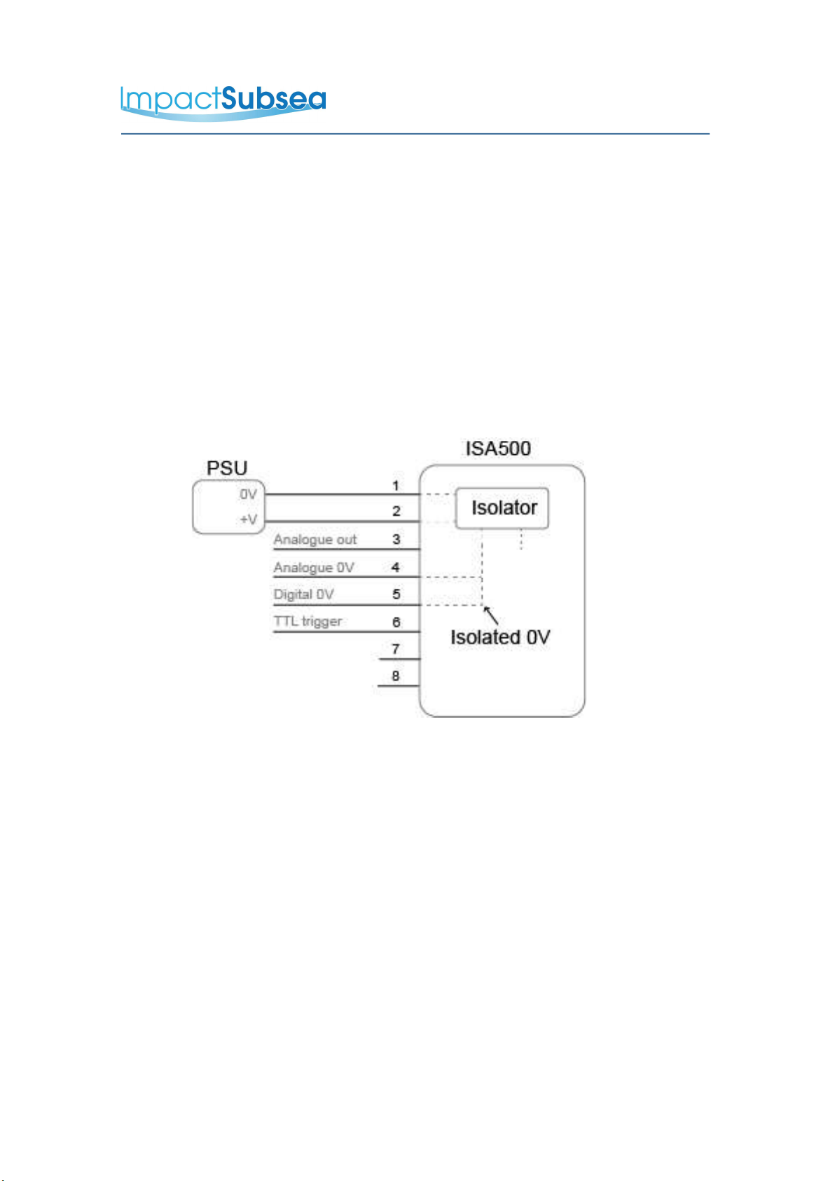
3.1.2 Power
The ISA500 is polarity protected and fused with a 400mA resettable poly
fuse. Internal circuitry isolates the supply from the outside environment
requiring the serial interface, TTL trigger and analogue output to use the
digital and analogue 0V reference pin.
3.1.3 Serial Interface
The RS232 and RS485 interface is isolated from the supply and has in-line
fused protection on the serial lines. A prolonged transient voltage on these
line will blow the surface mount fuses which will require replacement by
Impact Subsea or an approved distributor.
3.1.4 RS232 Wiring
Note: RS232 will not function if the digital 0V pin is not use as the
RS232 ground.
© Impact Subsea Ltd 7

www.impactsubsea.com
Innovative Underwater Products
3.1.5 RS485 Wiring
The RS485 termination resistor is software selectable.
The digital 0V must be connected on an RS485 interfaces, otherwise
the voltage potential between one of the A+ or B- lines to ground could
reach a damaging level
© Impact Subsea Ltd 8
www.impactsubsea.com
Innovative Underwater Products
3.1.6 Analogue Out and TTL Trigger
The Analogue interface can be configure to output voltage or current. It is
isolated from the supply and has in-line fused protection. A prolonged
transient voltage on this line will blow the surface mount fuses which will
require replacement by Impact Subsea or an approved distributor.
The TTL input can be used to trigger a ping, update the analogue output and
transmit the user selected serial string. These events can happen when the
trigger is connected to digital 0V or disconnected, the software allows the
user to choose.
Notes:
TTL trigger input is referenced to Digital 0V
Analogue out is referenced to Analogue 0V
© Impact Subsea Ltd 9
www.impactsubsea.com
Innovative Underwater Products
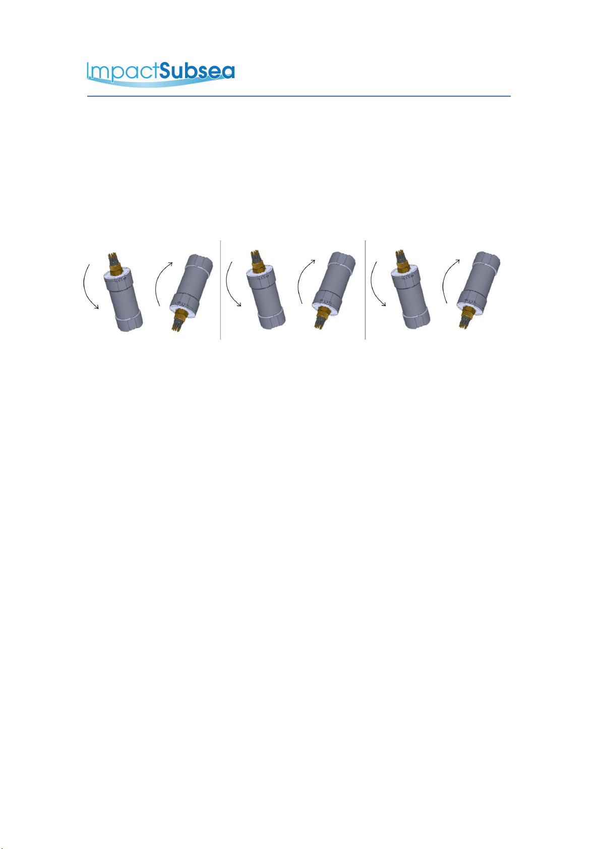
3.1.7 Establishing Communications
The default serial settings are RS232, 9600, N81
If the ISA500 is tilted from vertical to upside down 3 times within the first 10
seconds of power up then it will temporarily configure the serial interface to
the default (RS232, 9600, N81) and output an ASCII message displaying the
settings.
Note: When the device is powered cycled the serial interface setting will
revert back to the last configuration.
3.1.8 Connector Mating
When mating the cable to the SubConn connector, to maximise the life of the
connector, it is important to observe the following:
–Always apply grease before mating. Molykote 44 Medium grease must be
used.
–Disconnect by pulling straight, not at an angle.
–Do not pull on the cable and avoid sharp bends at cable entry.
–Do not over-tighten the bulkhead nut.
Do not expose the connector to extended periods of heat or direct sunlight. If
a connector becomes very dry, it should be soaked in fresh water before use
© Impact Subsea Ltd 10

www.impactsubsea.com
Innovative Underwater Products
3.1.9 Connector Cleaning
General cleaning and removal of any accumulated sand or mud on a
connector should be performed using spray based cleaner (for example
Isopropyl Alcohol).
New grease must be applied again prior to mating.
3.2 Location
When evaluating the installation location of the ISA500, there are several
factors to consider to achieve optimum operation:
–Acoustics (Altitude Measurement)
–Magnetic Disturbers (Heading)
–Alignment with Vehicle (Pitch/Roll)
–Heat Sources (Temperature Measurement)
3.2.1 Acoustics (Altitude Measurement Performance)
The transducer must have a clear view of the seabed. Any items which
obstruct this view may result in erroneous Altitude measurements. If entirely
obstructed, no Altitude readings will be possible.
Ideally the ISA500 should not be operated in close proximity to other
acoustic equipment with the same operational frequency (500kHz). Other
acoustic equipment may cause the ISA500 to produce erratic Altitude
readings.
In some instances, if the ISA500 is found to be causing interference with
other acoustic systems, the operational frequency can be adjusted to move it
out of band with the other equipment – see Section 5 for details.
3.2.2 Magnetic Disturbers (Heading Performance)
Where the heading output is to be used, the ISA500 should be mounted as
© Impact Subsea Ltd 11

www.impactsubsea.com
Innovative Underwater Products
far as possible from sources of magnetic interference.
Electrical items which can cause magnetic interference include motors,
transformers and valve packs. Ferrous metals, or any other
magnetically active materials will also have influence on the heading reading.
Thus, where possible, the unit should be installed as far as possible from
magnetically active materials.
3.2.3 Alignment with Vehicle (Pitch/Roll Accuracy)
When mounting vertically, the ISA500 should be mounted with the
transducer facing downwards (to the seabed) and the indentation in the
connector end cap pointing forwards, in the direction of forward vehicle
travel:
When mounting horizontally (for horizontal range measurements) the
ISA500 should be mounted with the transducer facing in the direction of
measurement to be made, with the indentation in the connector end cap
pointing upwards:
© Impact Subsea Ltd 12

www.impactsubsea.com
Innovative Underwater Products
3.2.4 Heat Sources (Temperature Accuracy)
In order for the ISA500 to read the ambient temperature of the water, it
should not be installed in close proximity of any heat sources (such as
Hydraulic Power Packs).
3.3 Mounting
The ISA500 should be mounted using clamps around the mid section of the
body. The forward looking unit has a 55mm recess in the main body to enable
a clamp to be tightened securely around the unit. The right angled unit has a
46mm recess.
Ideally a non-metallic clamp should be used, however in the event that this is
not possible, effort should be made to electrically isolate the clamp from the
ISA500 housing. This can be achieved by using rubber or plastic strips
around the body of the ISA500.
The ISA500 has two flats, on either side of the body – these are to enable the
unit to sit tightly against another flat surface if available. These flats also help
prevent the unit moving when on the workbench for testing.
© Impact Subsea Ltd 13

www.impactsubsea.com
Innovative Underwater Products
4.0 Operation
4.1 Use with seaView software
The ISA500 is supplied with the highly intuitive Impact Subsea seaView software on
USB. The latest version of seaView can be downloaded from
www.impactsubsea.com
seaView is designed to operate all of the Impact Subsea sensors. Single sensors
can be operated, or multiple sensors together.
seaView is designed for use with a PC running the Windows 7, 8 or 10 operating
system and require Microsoft's .net framework 4.5.2 or above
seaView uses an advance framed binary protocol to communicate to the ISA500
and can do so over RS232 or RS485 at any standard baud rates above 4800. The
parity must be none, stop bits 1 and data bits 8. If the ISA500 communication
settings differ from this then perform the communications reset as described in the
establishing communications section of this manual.
All settings and offsets are saved to the ISA500 device flash memory.
Impact Subsea Software
© Impact Subsea Ltd 14

www.impactsubsea.com
Innovative Underwater Products
4.2 Integration with systems
Conceptually there are two modes of operation, Interrogated and autonomous.
Integration mode requires a master to request the ISA500 to make a measurement
and report this back.
The ISA500 can be interrogated by the user defined interrogation string, or by the
TTL trigger input. Upon interrogation the ISA500 will make a measurement and
report back the result over the configured output, whether this be a serial string or
analogue voltage / current loop output.
Autonomous mode will make a measurement and output the result over serial or
analogue at a specified time interval.
The ISA500 can be configured to operate in one or both of these modes at the
same time.
ISA500's with the HMRU option make use of the same interrogated and
autonomous mechanises to output heading pitch and roll data over the serial
interface.
4.3 Understanding advanced features
Some serial output strings for altitude measurement report back the energy level of
the echo and a correlation factor.
The energy level ranges from 0 to 1 where 1 represents full saturation of the ISA500
receiver. An energy level of 0.707 (square root of 2) is the theoretical perfect level
as it represents the energy of a pure sine wave with an amplitude utilising the
maximum dynamic range of the ISA500.
The correlation factor ranges from 0 to 1 which represents a quality factor of the
returned echo. A value of 1 would represent a return echo of perfection with
negligible noise and distortion.
© Impact Subsea Ltd 15

www.impactsubsea.com
Innovative Underwater Products
The correlation value can be used alone as a trust factor where low values such as
0.3 mean there a good possibility it's a false reading. A more detailed picture can be
build by combining this information with the energy level as shown in the table:
Low energy levels High energy levels
Low correlation Weak signal probably false
reading
High noise level most
likely a false reading
High correlation Weak signal but likely a good
reading
Ideal conditions very
trust worthy readings
These values can also give some insight for adjusting the transmit power. If the
energy level is low then consider increasing the amplitude and length of the transmit
pulse.
The ISA500 does not average or filter readings in any way. This provides zero lag
making it ideal for control systems.
A simple reliable target tracking algorithm can be created by applying the last known
altitude reading to analyse the multi echo outputs. Using the correlation and energy
values will further improve the reliability.
© Impact Subsea Ltd 16

www.impactsubsea.com
Innovative Underwater Products
5.0 Servicing
The ISA500 is a highly robust Altitude and Attitude measurement device. The unit
has been designed to require minimal maintenance, and as such there are no user
serviceable components within the unit.
The unit should be rinsed in fresh water to remove growth and salt deposits. If
required a light detergent (such as that used to clean household dishes) can be
used.
DO NOT USE SOLVENTS TO CLEAN THE UNIT
Following rinsing the unit should be dried with a cloth.
The connector should be cleaned, and a light coating of Molykote 44 Medium
grease should be applied.
The unit should be stored in its original case, in a cool, dry place.
It is recommended that the unit be returned to Impact Subsea Ltd, on an annual
basis to have a health check and service conducted.
© Impact Subsea Ltd 17

www.impactsubsea.com
Innovative Underwater Products
6.0 ASCII Output Strings
6.1 Altitude
ID1: Impact Subsea altitude and temperature
String format:
$ISADS,ddd.ddd,M,tt.t,C*xx<CR><LF>
ddd.ddd = distance in meters from the transducer face to the target.
tt.t = temperature in Celsius
xx = NEMA standard checksum
ID2: Impact Subsea altitude, signal level, correlation and temperature
String format:
$ISADI,ddd.ddd,M,e.eeee,c.cccc,tt.t,C*xx<CR><LF>
ddd.ddd = distance in meters from the transducer face to the target.
e.eeee = energy level (0 to 1)
c.cccc = correlation factor (0 to 1)
tt.t = temperature in Celsius
xx = NEMA standard checksum
ID3: Impact Subsea mutli echo output
String format:
$ISAMD,tt.t,C,ddd.ddd,...*xx<CR><LF>
tt.t = temperature in Celsius
ddd.ddd = distance in meters from the transducer face to the target.
… = another ddd.ddd reading.
xx = NEMA standard checksum
Example string format for 3 echoes (Note: 10 echoes maximum number of multi-
echoes that can be detected):
$ISAMD,tt.t,C,ddd.ddd,ddd.ddd,ddd.ddd*xx<CR><LF>
© Impact Subsea Ltd 18

www.impactsubsea.com
Innovative Underwater Products
ID4: Impact Subsea mutli echo output with signal level, correlation and
temperature
String format:
$ISAMI,tt.t,C,ddd.ddd,e.eeee,c.cccc,...,...,...*xx<CR><LF>
tt.t = temperature in Celsius
ddd.ddd = distance in meters from the transducer face to the target.
e.eeee = energy level (0 to 1)
c.cccc = correlation factor (0 to 1)
,...,...,... = another ddd.ddd,e.eeee,c.cccc reading
xx = NEMA standard checksum
Example string format for 2 echoes
$ISAMD,tt.t,C,ddd.ddd,e.eeee,c.cccc,ddd.ddd,e.eeee,c.cccc*xx<CR><LF>
ID5: Tritech 3P3
String format:
ddd.dddm<CR><LF>
ddd.ddd = distance in meters from the transducer face to the target.
ID6: Tritech 2P3
String format:
dd.dddm<CR><LF>
dd.ddd = distance in meters from the transducer face to the target.
ID7: Tritech 3P2
String format:
ddd.ddm<CR><LF>
ddd.dd = distance in meters from the transducer face to the target.
© Impact Subsea Ltd 19

www.impactsubsea.com
Innovative Underwater Products
ID8: Tritech multidrop
String format:
xddd.dddm<CR><LF>
x = node address. This the the first character of the interrogation string.
ddd.ddd = distance in meters from the transducer face to the target.
ID9: Benthos
String format:
Rdd.dd<CR><LF> or when there's no echo return Rdd.ddE<CR><LF>
dd.dd = distance in meters from the transducer face to the target.
ID10: Valeport
String format:
$PRVAT,dd.ddd,M,0000.000dBar*xx<CR><LF>
dd.dd = distance in meters from the transducer face to the target.
xx = NEMA standard checksum
ID11: SDDBT
String format:
$SDDBT,,f,ddd.dddd,M,,F*xx<CR><LF>
ddd.dddd = distance in meters from the transducer face to the target.
xx = NEMA standard checksum
ID12: Tritech bathy mode
© Impact Subsea Ltd 20
Other manuals for ISA500
1
Table of contents
Other Impact Subsea Accessories manuals


