Entron WA2 User manual

BF ENTRON LTD.
Monitoring equipment
Weld Analyser
WA2

M O N I T O R I N G E Q U I P M E N T
Weld Analyser WA2
BF ENTRON Ltd.
Building 0 • The Pensnett Estate
Kingswinford • West Midlands • DY6 7FQ
Phone +44 (0)13 4 455401 • Fax +44 (0)13 4 455551
www.bfentron.co.uk
Issue Date Comment
1 02-11-06 Initial release
2 09-01-07 Charger description
3 14-01-13 WA Terminal features
4
11
-
11
-
13
USB
features
. Integrator output.
5
23
-
04
-
14
DC duration amendments
6
13
-
05
-
14
WA Terminal time/date feature
7
17
-
0
-
15
Current sensors
09-10-17 Current sensor
9 29-11-17 Logo changed

Table of Contents
Introduction .............................................................................. 1
Key features............................................................................. 2
Specifications........................................................................... 3
Installation................................................................................ 4
Charging the batteries..................................................................... 4
Current sensors .............................................................................. 5
Connectors............................................................................... 7
Current sensor ................................................................................ 7
USB port ......................................................................................... 7
Integrator output.............................................................................. 7
Controls.................................................................................... 8
Keypad............................................................................................ 8
Display ............................................................................................ 9
Data display...........................................................................................9
Detail display .........................................................................................9
Setup display .......................................................................................10
File display...........................................................................................12
Measuring welds .................................................................... 13
Capturing data with WA terminal ............................................ 14
Installing WA terminal ................................................................... 16
Connecting your WA2 ................................................................... 17
USB port ....................................................................................... 17
Using WA Terminal ....................................................................... 20
Communications Port.................................................................... 21
Record Start/Stop ......................................................................... 21
Save.............................................................................................. 21
Auto-save...................................................................................... 22
Data display .................................................................................. 22
Closing WA Terminal .................................................................... 22
Removing WA Terminal ................................................................ 22
Data persistence ........................................................................... 23

I N T R O D U C T I O N
1
Introduction
An overview of the WA2
he Weld Analyser WA2 is an RISC based instrument designed for the
comprehensive real-time analysis of resistance welds. It is a compact hand-
held battery operated unit that is an ideal tool for welding, maintenance and
quality control personnel.
The WA2 is capable of measuring AC and MF DC welding current, the number of
pulses in the weld and the duration of each weld. The information is displayed on a
backlit FSTN LC display and may be stored in non-volatile EEPROM. The WA2 may
also be connected to a computer to extend its storage capabilities.
Every WA2 is supplied with a traceable calibration certificate.
Section
1
T

I N T R O D U C T I O N
2
Key features
•Portable, hand-held compact unit
•12 x 64 LC display with yellow/green backlight and antiglare coating
•Tactile keypad
•Powered by three rechargeable AA batteries
•Automatic power-down after 10 minutes of inactivity
•Menu driven commands
•USB port (data exchange only)
•Measures RMS AC and DC welding current
•Selectable ranges of 60, 120, 1 0, 240 and 300 kA
•High and low current indicators
•Measures welding time in ½ cycles up to 9999 cycles (AC) or 10 ms intervals
up to 199.9 seconds (DC)
•Captures up to 300 ½ cycles (AC) or 3 seconds (DC)
•Measures conduction angle for each ½ cycle (AC)
•Over- and under-range indicators
•Weld indicator
•Multi-pulse weld indicator

I N T R O D U C T I O N
3
S ecifications
dimensions
5w x 30d x 170h mm
weight
500 g including batteries
operating temperature
0º to 45º C ambient
power source
three
rechargeable
NiMH AA batteries
battery life
6
hours minimum, 2000mAh
@ 25º C
display
12 x 64 pixels FSTN transflective
keypad
e
mbossed disc tactile switches
weld current
2 to 300 kA, accuracy ± 2 % of full scale
weld time
0.5 to 9999 cycles (AC) or 0.01 to 199.9
seconds (DC)
capture time
300 ½ cycles (AC) or 3 seconds (DC)
with programmable end-of-capture
conduction angle
0º to 1 0º ± 4º (AC)
pulse count
1 to 99

I N S T A L L A T I O N
4
Installation
Connecting the WA2
he rechargeable batteries supplied with the WA2 may be in a discharged state.
It is recommended that the batteries are fully recharged before using the WA2.
Charging the batteries
Use only the supplied charger. Other chargers must not be used.
•Ensure that the correct mains adaptor is fitted for your territory. Consult the
documentation supplied with the charger.
•Ensure that the 2.5 mm jack plug adaptor is fitted and connected correctly –
positive + terminal to positive + terminal.
•Switch off the WA2.
•Ensure the charger is switched off. Connect it to the WA2 and switch the
charger on. The red Power LED indicates that the charger is ready for use.
Section
2
T
Caution: use only
NiMH batteries rated at 1.2 V. Alkaline batteries rated at 1.5
V must not be used.
Warning: do not connect or disconnect the charger while it is switched on.
Note: the USB connection cannot be used to recharge the batteries.

I N S T A L L A T I O N
5
•If the WA2 batteries are new or have only been used a few times, use the
charger’s discharge mode before charging. Consult the charger’s
documentation.
•If the batteries are older or have been conditioned by the charger’s discharge
cycle, the charger will fast charge the batteries and then revert to a trickle
charge; this may take several hours depending on the condition of the batteries.
•The green Ready indicates that the batteries are fully charged. The indicator
will flash after two minutes and the charger will revert to trickle charge. At this
stage, charging is complete.
•Switch off the charger and disconnect it from the WA2. The WA2 is now
ready to use.
Current sensors
The WA2 is supplied with a 6” (150 mm) diameter tube-
profile current sensor:
Flat-profile current sensors are also available:
3” (75 mm) diameter W296557
6” (150 mm) diameter W29655
12” (300 mm) diameter W296559

I N S T A L L A T I O N
6
Connect the WA2 as shown below:
Note that the joint
in the current
sensor can result
in reduced
accuracy and the
sensor should be
orientated as
shown.
sensor
computer (optional)
oscilloscope (optiona
l)

I N S T A L L A T I O N
7
Connectors
Current sensor
Connect the calibrated current sensor to the WA2.
USB ort
Connect to a computer USB 2.0 port using a USB A to
USB mini B cable if required.
The USB device is provided by Future Technology Devices International Ltd. and
Windows drivers are included on the WA2 companion CD. Updated drivers and
drivers for Mac OS and Linux can be found on the FTDI website:
http://www.ftdichip.com/Drivers/VCP.htm. Check for updated drivers and install
the driver for your system by following the appropriate installation guide:
http://www.ftdichip.com/Support/Documents/InstallGuides.htm
Integrator out ut
Connect an oscilloscope or other recording instrument
if required.
The signal corresponds to the integrated output from
the current sensor, maximum amplitude +/- 15 V.
Caution: the integrator out ut should only be connected to high im edance
recording instruments.

C O N T R O L S
8
Controls
Operating the WA2
he WA2 is controlled via a tactile keypad in conjunction with a graphical LC
display.
Key ad
The function of the keys is described below:
Key
Function
Data display Detail display Setup display
File display
power on/off
backlight on/off
previous/next
pulse
scroll
up/down previous/next parameter
n/a
goto
start/end
when used
with scroll
keys
decrease/increase value
go to next display/confirm
Section
3
T
C O N T R O L S
9
Dis lay
The keypad allows navigation through the features of the WA2 via a number of
different displays as described below:
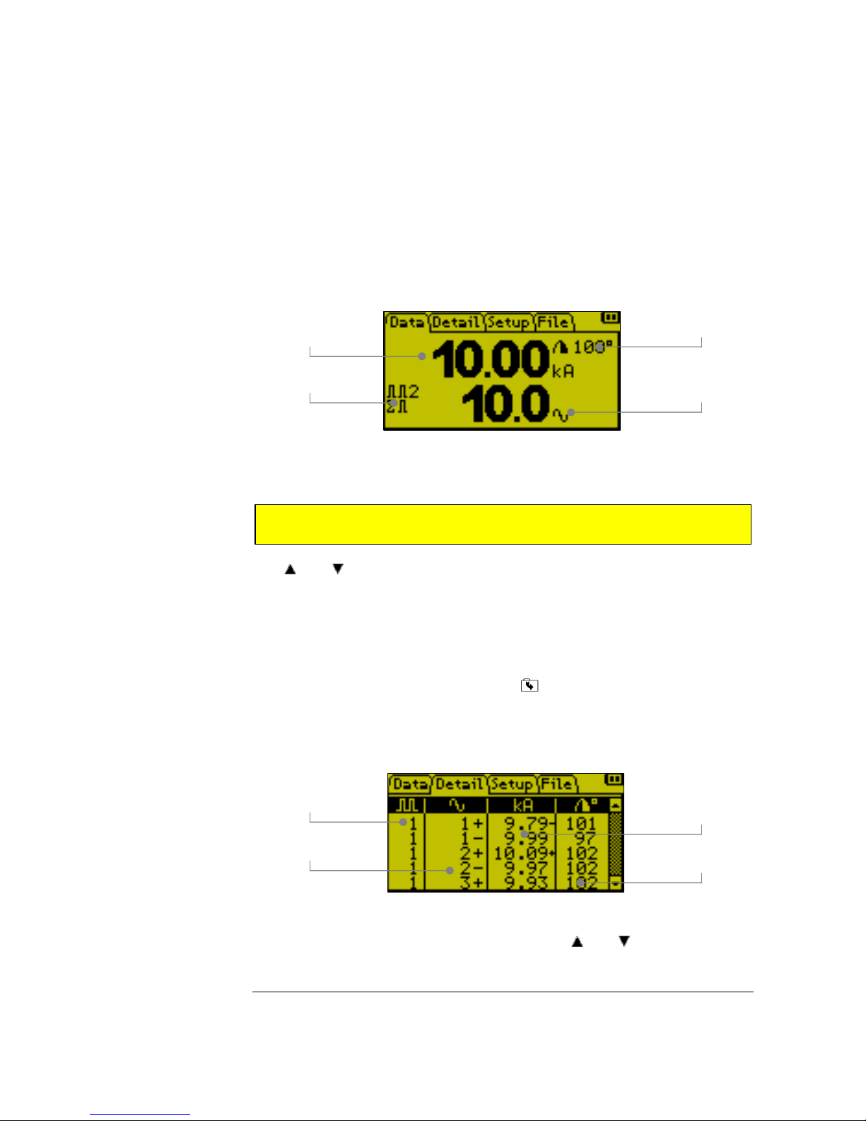
Data dis lay
This is the default display and shows a summary of the most recent weld. The diagram
shows an example for an AC weld:
For DC welds, the weld time is shown in ms and cycles. The conduction angle is not
applicable to DC welds.
The and keys may be used to select the previous or next pulse in the weld (if
applicable). The pulse count is incremented if there is an interruption in the current of
1 cycle (AC) or 10 ms (DC); an interruption in the current of more than 200 ms is
interpreted as the end-of-weld.
Detail dis lay
The Detail Display is accessible by pressing from the Data Display. The Detail
Display shows the detailed results of the most recent weld. The diagram below shows
an example for an AC weld:
For DC welds, the ½ cycles are replaced with the cumulative weld time in ms. The
conduction angle is not applicable to DC welds. The and keys may be used to
Note: DC weld currents less than 4.0kA may lead to inaccuracies in the
measured weld time.
conduction angle of last weld
weld time in cycles
weld current in kA
pulse count and pulse
number if appropriate
pulse number (in weld)
cycle number (in pulse)
current for every ½ cycle
+ indicates highest ½ cycle
- indicates lowest ½ cycle
conduction angle for each
½ cycle
C O N T R O L S
10
The shaded sections
of the weld are not
included in the dc
current and duration
calculations
scroll through the readings. Press and to go to the start of the list; press and
to go to the end of the list.
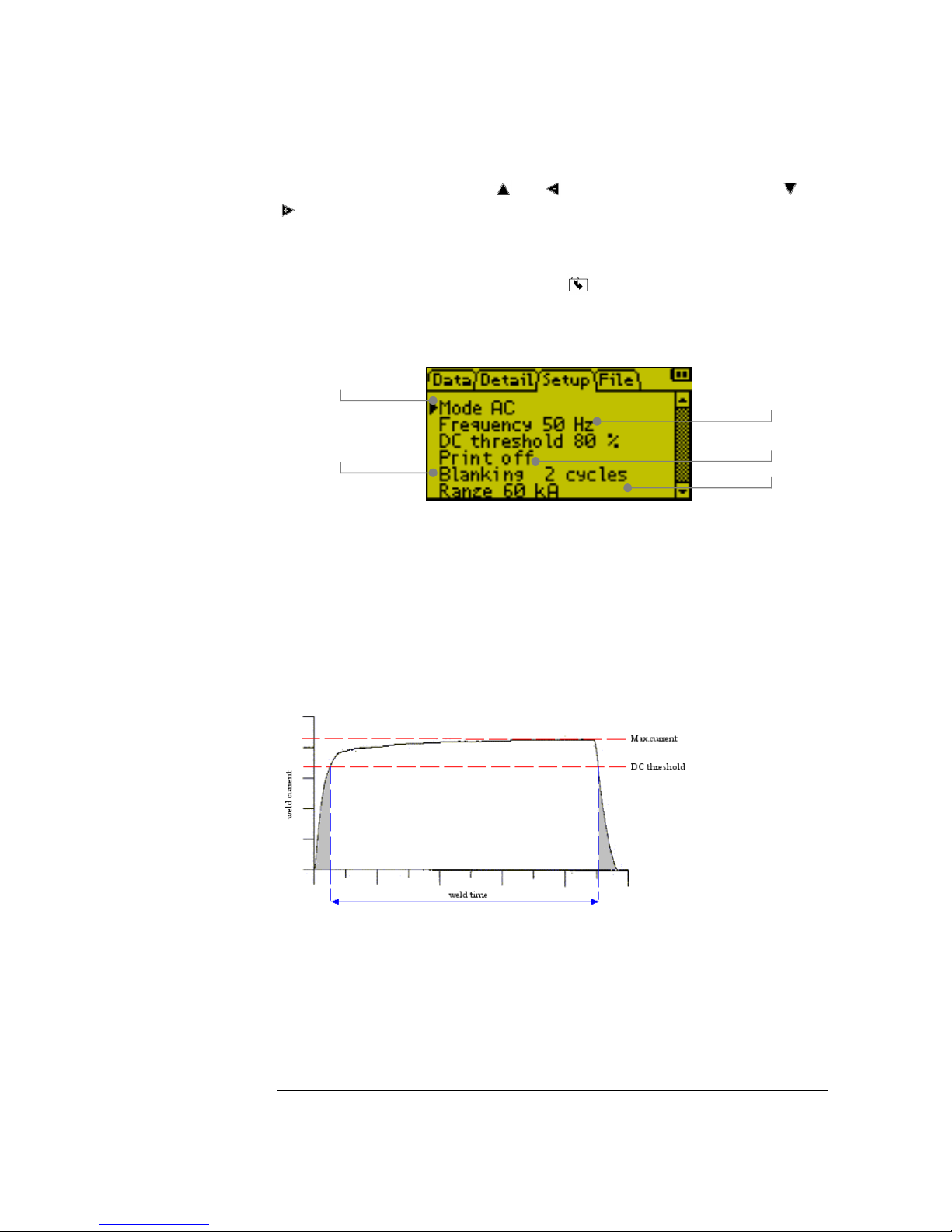
Setu dis lay
The Setup Display is accessible by pressing from the Detail Display. The Setup
Display allows the WA2 to be configured for specific applications. The diagram below
shows the typical settings for a 50 Hz AC application.
The Mode parameter determines the type of welding current to be measured, AC or
DC.
The Frequenc parameter relates to the mains supply frequency. If DC mode is
selected, the Frequenc parameter is used to calculate the equivalent weld time in
cycles for the Data Display.
The DC threshold determines the % of the maximum weld current that is included in
the current and duration calculations; it is not applicable in AC mode.
The Print parameter determines the output from the USB port at the end of each
weld. If printing is off, there is no output; if printing is set to all, the WA2 outputs the
results of every ½ cycle (AC) or 10 ms (DC) reading; if printing is set to summar , the
WA2 outputs the average current and duration for the weld.
The Blanking parameter is used to mask transient conditions at the start of the weld.
AC welding
cycles e cluded from
the RMS calculation
line freq
uency
printing off/all/summary
current range

C O N T R O L S
11
The Range parameter is used to determine the maximum current that can be
measured. This parameter should match the setting on the optional attenuator module
or set to 60 kA if no attenuator module is used.
The Auto shutdown parameter (not shown) is used to enable or disable the automatic
shutdown feature. If this parameter is set to on, the WA2 will shutdown after 10
minutes of inactivity to conserve battery power. If this parameter is set to off, the WA2
will not automatically shutdown.
The Stop parameter (not shown) can be used to capture a specific section of a long
weld. The WA2 will capture 300 cycles (AC) or 3 seconds (DC) of welding prior to the
Stop parameter.
If DC mode is selected, the Blanking and Stop parameters are programmed in ms.

C O N T R O L S
12
File dis lay
The File Display is accessible by pressing from the Setup Display. The File Display
allows welds to be stored and retrieved for analysis at a later date.
The display shows the memory that is available for storing welds; the value will change
according to the quantity and duration of welds that are stored.
The Action parameter determines if the weld will be saved, loaded from memory,
erased from memory or printed.
The ID is a numeric identifier that is used to access the stored weld.
Select an action and an ID (if applicable), then press to confirm the action. The
WA2 will perform the action and then revert to the Data Display.
available memory
E Empty
F Full
file ID
0 to 99 or all
action cancel / save /
load / erase / print

M E A S U R I N G W E L D S
13
Measuring welds
Using the WA2
hen the WA2 is charged and installed as described in Section 2, it is ready
to measure the parameters of the every weld.
•Connect the WA2 sensor to the welding machine and ensure the sensor is
connected securely to the WA2.
•Switch on the WA2 by pressing the button; wait for the Data Display to
appear .
•Use the button to access the Setup Display and check that the values
correspond to the application. Select the Print format if required.
•Use the button to return to the Data Display.
•Use the welding machine to produce a weld and check that the WA2 has read
the welding current, duration and (if appropriate) the conduction angle and
pulses. The Data Display shows a summary of the weld.
•Use the button to view the results in greater detail using the Detail Display.
Use the and to scroll through the list.
•Use the button to access the File Display and save the results if required.
The results can be retrieved, printed or erased at a later date if required.
Section
4
W

C A P T U R I N G D A T A W I T H W A T E R M I N A L
14
Ca turing data with WA terminal
An overview of WA Terminal
he WA Terminal utility is a Microsoft Windows compatible program that
allows you to capture the data from your WA2 in applications where long-
term data logging is required.
WA Terminal connects to your WA2 via your computer’s USB port. As your WA2
records each weld the information is transmitted to WA Terminal where the
information can be inspected, saved or printed. The program has minimal setup
requirements and virtually unlimited storage capacity.
Ke features
•Microsoft Windows compatible
•Minimal installation
•Minimal set-up requirements
•Minimal performance overhead
•Virtually unlimited storage capacity
•Data is recorded in real time
•Data can be saved automatically
Section
5
T

C A P T U R I N G D A T A W I T H W A T E R M I N A L
15
Specifications
compatibility
Microsoft Windows:
/7/Vista/XP
Server 200
minimum
requirements
Pentium 233
-
megahertz (MHz) processor
or faster (300 MHz is recommended)
At least 64 megabytes (MB) of RAM (12
MB is recommended)
At least 1.5 gigabytes (GB) of available
space on the hard disk
Keyboard and a compatible pointing
device
Video adapter and monitor with Super
VGA ( 00 x 600)or higher resolution
USB 2.0 port
USB A to USB mini B cable
user interface
conforms to user’s display and scheme
settings
resizeable main window with persistent
settings
horizontally and vertically scrollable data
display
Start/Stop recording function
Start/Stop recording indicator
Save data function
Auto-save data function
communication ports
COM1 to COM

C A P T U R I N G D A T A W I T H W A T E R M I N A L
16
Installing WA terminal
WA Terminal is a self-contained program and requires no installation. The program is
supplied as a single executable file named WAT.EXE and is included on the WA2
companion CD. Copy the WAT.exe file to a location on your computer and run the
program from there.

C A P T U R I N G D A T A W I T H W A T E R M I N A L
17
Connecting your WA2
Connect your WA2 as shown below:
USB ort
Connect to a computer USB 2.0 port using a USB A to
USB mini B cable.
The USB device is provided by Future Technology Devices International Ltd. and
Windows drivers are included on the WA2 companion CD. Updated drivers and
drivers for Mac OS and Linux can be found on the FTDI website:
http://www.ftdichip.com/Drivers/VCP.htm. Check for updated drivers and install
the driver for your system by following the appropriate installation guide:
http://www.ftdichip.com/Support/Documents/InstallGuides.htm
The USB driver will allocate a COM port number to be used for the connection. The
COM port number can be determined via Windows Device Manager as follows:
Other manuals for WA2
1
Table of contents
Other Entron Measuring Instrument manuals

Popular Measuring Instrument manuals by other brands


SIGLENT
SIGLENT SSA3021X user manual

Flow vision
Flow vision FC50-CA Instructions for installation

YOKOGAWA
YOKOGAWA IS8000 user manual

Topcon
Topcon KR-1W user manual

Magnetrol
Magnetrol Echotel 335 Installation and operating manual

SENSIT Technologies
SENSIT Technologies ULTRA-TRAC APL Quick start instructions


