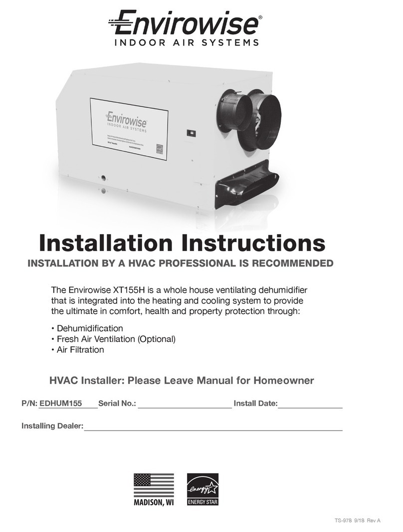
Envirowise XT205H User manual

The Envirowise XT205H is a whole house ventilating dehumidier
that is integrated into the heating and cooling system to provide
the ultimate in comfort, health and property protection through:
• Dehumidication
• Fresh Air Ventilation (Optional)
• Air Filtration
TS-979 9/18 Rev A
P/N: EDHUM205 Serial No.: Install Date:
Installing Dealer:
HVAC Installer: Please Leave Manual for Homeowner
Installation Instructions
INSTALLATION BY A HVAC PROFESSIONAL IS RECOMMENDED

Safety Instructions ...................................................................... 3
Specifications .............................................................................. 4
General Set Up ............................................................................ 5
Attaching Duct Collars................................................................. 6
Electrical Requirements .............................................................. 7
Drain Installation ......................................................................... 8
Ducting to HVAC Systems............................................................ 9
Recommended HVAC System Installations ........................................ 10
No Existing Ductwork Installation ....................................................... 12
Fresh Air Ventilation .................................................................. 13
Determine Ventilation Requirements ................................................... 14
Controls ..................................................................................... 15
Filter Instructions ...................................................................... 18
Optional Accessories................................................................. 19
Service....................................................................................... 20
Troubleshooting................................................................................... 20
TABLE OF CONTENTS
Ingersoll Rand is committed to manufacturing quality products. To maintain
our standards, product specications may change without notice.
Ingersoll Rand, 6200 Troup Hwy. Tyler, TX 75707
Items Included in Box:
• Envirowise XT205H Dehumidier
• Envirowise XT205H Installation Instructions
• Envirowise XT205H Leveling Feet

3
Envirowise XT205H Installation Instructions
SAFETY INSTRUCTIONS
WARNING!
THIS SYMBOL MEANS IMPORTANT INSTRUCTIONS. FAILURE TO HEED THEM
CAN RESULT IN SERIOUS INJURY OR DEATH.
READ THE INSTALLATION, OPERATION AND MAINTENANCE INSTRUCTIONS CAREFULLY
BEFORE INSTALLING AND OPERATING THIS DEVICE. PROPER ADHERENCE TO
THESE INSTRUCTIONS IS ESSENTIAL TO OBTAIN MAXIMUM BENEFIT FROM YOUR
ENVIROWISE WHOLE HOUSE VENTILATING DEHUMIDIFIER.
CAUTION!
THIS SYMBOL MEANS IMPORTANT INSTRUCTIONS. FAILURE TO HEED THEM
CAN RESULT IN INJURY OR MATERIAL PROPERTY DAMAGE.
Registrations
The Envirowise XT205H conforms to unied standard UL 60335-2-40 and CSA standard C22.2.60335-2-40.
CAUTION!
READ ALL INSTRUCTIONS BEFORE BEGINNING INSTALLATION.
ALWAYS USE CAUTION AND WEAR CUT RESISTANT GLOVES WHEN HANDLING SHEET
METAL.
IMPROPER INSTALLATION MAY CAUSE PROPERTY DAMAGE OR INJURY.
INSTALLATION, SERVICE, AND MAINTENANCE MUST BE PERFORMED BY A QUALIFIED
SERVICE TECHNICIAN.
DEHUMIDIFIER IS HEAVY. HANDLE WITH CARE AND FOLLOW INSTALLATION INSTRUCTIONS.
DO NOT USE IN POOL APPLICATIONS, OR WARRANTY WILL BE VOID.
NEVER OPERATE A UNIT WITH A DAMAGED POWER CORD. IF THE POWER CORD IS
DAMAGED, IT MUST BE REPLACED BY THE MANUFACTURER, ITS SERVICE AGENT, OR A
SIMILARLY QUALIFIED PERSON IN ORDER TO AVOID A HAZARD.
THIS APPLIANCE IS NOT INTENDED FOR USE BY PERSONS (INCLUDING CHILDREN) WITH
REDUCED PHYSICAL, SENSORY OR MENTAL CAPABILITIES, OR LACK OF EXPERIENCE
OR KNOWLEDGE, UNLESS THEY HAVE BEEN GIVEN SUPERVISION OR INSTRUCTION
CONCERNING THE USE OF THE APPLIANCE BY A PERSON RESPONSIBLE FOR THEIR
SAFETY. CHILDREN SHOULD BE SUPERVISED TO ENSURE THAT THEY DO NOT PLAY WITH
THE APPLIANCE.
WARNING!
120 VOLTS MAY CAUSE SERIOUS INJURY FROM ELECTRIC SHOCK.
DISCONNECT ELECTRICAL POWER BEFORE STARTING INSTALLATION OR
SERVICING, AND LEAVE POWER DISCONNECTED UNTIL INSTALLATION OR
SERVICE IS COMPLETED.

4Envirowise XT205H Installation Instructions
SPECIFICATIONS
Part Number: EDHUM2051H1MDA
Blower: 526 CFM @ 0.0" WG
495 CFM @ 0.2" WG
458 CFM @ 0.4" WG
Power: 1525 Watts @ 80°F and 60% RH
Supply Voltage: 115 VAC – 1phase – 60 Hz
Current Draw: 13.2 Amps
Transformer Protection: Push Button Reset (located near power cord)
Circuit Requirement: 20 Amp Dedicated
Energy Factor: 2.7 L/kWh
Operating Range: 49°F Min, 95°F Max (Inlet Air Temperature)
Sized For: Up to 5,000 Square Feet
Minimum Performance at: 80°F and 60% RH 70°F and 60% RH
Water Removal: 205 Pints/Day 153 Pints/Day
Efciency: 5.7Pints/kWh 5.0Pints/kWh
Duct Connections: 6" Round Inlet; 10" Round Inlet; 10" Oval Outlet
Air Filter: MERV-11, Mini Pleat
Efciency: 65%ASHRAEDustSpot
Size: 16" x 20" x 2"
Optional Air Filter: MERV-14,EmbossedPleat(willneedlterhousing)
Efciency: 95%ASHRAEDustSpot
Size: 20" x 24" x 4"
Power Cord: 9', 115 VAC, Ground
Internal Insulated Cabinet: Yes
Drain Connection: 3/4" Threaded Female NPT
Refrigerant Type: R410A
RefrigerantAmount: 2lbs.,1oz.
Dimensions: Unit With Collars Unit Without Collars Shipping
Width: 20 1/4" 20 1/4" 25"
Height: 213/4" 213/4" 28"
Length: 411/2" 373/4" 42"
Weight: 140lbs. 139lbs. 173lbs.
FRONT VIEW
20 1/4”
21 3/4”
21 3/4”
41 1/2”
37 3/4”
21 3/4”
21 3/4”
BACK VIEW
20 1/4”
SIDE VIEW

5
Envirowise XT205H Installation Instructions
GENERAL SET UP
CAUTION!
REMOVE COMPRESSOR SHIPPING TIE FROM THE UNIT. FAILURE TO REMOVE
SHIPPING TIE WILL CAUSE EXCESS VIBRATION TO BE TRANSMITTED TO THE FRAME.
Removal of Compressor Shipping Support
The Envirowise XT205H uses a compressor to power the refrigeration system.
To protect the compressor and refrigeration system during shipping, a plastic tie
wrap secures it to the unit’s frame. Remove the tie wrap by cutting the tie wrap
and pulling from the unit as shown. After removing tie wrap, insert plastic plugs
provided into the holes.
Important Precautions
•Thedeviceisdesignedtobeinstalledindoorsinaspacethatisprotectedfromrain
andooding.
•Installtheunitwithenoughspacetoaccessoneofthesidepanelsformaintenanceandservice.
•Avoiddirectingthedischargeairatpeople.
•Ifusednearawatersource,becertainthereisnochancetheunitcouldfallintothewaterorgetsplashedandthat
itispluggedintoadedicatedcircuitandGroundFaultCircuitInterrupter(GFCI)protectedoutlet.
•DONOTusethedehumidierasabenchortable.
• DO NOTplacethedehumidierdirectlyonstructuralbuildingmemberswithoutvibrationabsorbersorunwanted
noise may result. Place the Envirowise XT205H on supports to raise the base of the unit.
•AdrainpanwithaoatswitchMUSTbeplacedunderthedehumidierifinstalledabovealivingareaorabovean
areawherewaterleakagecouldcausedamage.
Location Considerations
•Allowsufcientclearancetohandletheunit’soveralldimensionsaswellasthenecessaryreturnandsupply
ductwork to the unit.
•Allowsufcientclearanceforlterremovalandtopreventairowobstruction.
• Electrical service access will require the
removalofasidepanel.Allowsufcient
clearance on a side of the unit.
•Locatethedehumidierinanareawherethe
cord’slength(9')easilyreachesa115VAC
electrical outlet with a minimum of a 20 Amp
circuit capacity.
•Locatethedehumidierinanareawhere
eldwiringthecontrol(lowvoltage)tothe
unit will be possible.
• It is recommended that a backdraft damper
beusedinthedischargeductofthe
Envirowise XT205H, especially when
connectingtothesupplyductingsystem.
The backdraft damper prevents supply air
fromcounterowingthroughtheEnvirowise
XT205Hwhenitisnotoperating.The
dehumidier’slocationshouldbechosen
to allow installation of this accessory if
necessary.
• The Envirowise XT205H may be suspended
fromstructuralmemberswithsteelhanger
strapsorasuitablealternative,ensuringthe
assemblysupportsthedehumidier’sbase
in its entirety. DO NOThangtheEnvirowise
XT205H from its cabinet.
•Allowforproperroutinganddrainageof
needed drain pipes.
Electrical Service Access
(Either Side)
Filter 9' Power Cord
Top View
Minimum
Clearance
For Filter
(Either Side)
15"
6" Fresh Air Intake (Optional)
10" Return Air Duct
10" Supply Air Duct
A
B
C
32 3/8"
With Collars Installed
26"
Without Collars Installed
B
C
Drain Port
A
Top View
41 1/2"
With Collars Installed
37 3/4"
Without Collars Installed
Drain Port 9' Power CordFilter
Minimum
Clearance
For Filter
(Either Side)
20"
6" Fresh Air Intake (Optional)
10" Return Air Duct
A
B
6” Fresh Air
Intake (Optional)
10” Return Air Duct
Electrical Service Access
(Either Side)
A
B
The 10” Supply Air Duct (not pictured) is
below the Fresh Air Intake and the Return
Air Duct. The same amount of clearance
is needed for the 10” Supply Air Duct.

6Envirowise XT205H Installation Instructions
ATTACHING DUCT COLLARS
Duct Collar Installation
Remove the two round ducts, oval duct, and oval duct seal and small bag of mounting hardware from inside
the rectangle opening.
Fresh Air Ventilation Duct
Fresh air ventilation is optional. Attach 6" diameter duct to the unit using the screws provided. The 6" duct
should be capped if fresh air is not desired. If setting up the unit to provide fresh air ventilation, see page 14.
Return Air Inlet
Attach 10" diameter duct collar to the unit with the screws provided.
Supply Air Outlet
Adhere seal onto the back of the oval duct and mount the duct to the front of the dehumidier using the screws
provided.
SIDE VIEW
FRONT VIEW
6" Fresh Air Inlet (Optional)
10" Return Air Inlet
10" Supply Air Outlet
A
B
C
A
B
CCollars and
hardware are
located here.

7
Envirowise XT205H Installation Instructions
The Envirowise XT205H plugs into a common grounded 115 VAC outlet. The device draws 13.2 Amps at
80°F and 60% RH. Locate the dehumidier in an area where the cord’s length (9') easily reaches a 115 VAC
electrical outlet with a minimum of 20 Amp circuit capacity. If used in an area that may become wet, a GFCI
protected circuit is recommended. Consult local electrical codes for further information.
Envirowise oers a variety of control devices for use with the Envirowise XT205H. The control is to be located
remotely from the dehumidier and placed in the space to be conditioned. A low voltage (24 Volt) control MUST
be used with the Envirowise XT205H and MUST be connected with low voltage (18-22 gauge) thermostat wire.
GENERAL SET UP
CAUTION!
DO NOT ALLOW THE 24V TERMINAL TO CONTACT THE COM/DMPR TERMINALS ON THE
ENVIROWISE XT205H OR DAMAGE TO THE TRANSFORMER WILL RESULT.
Electrical Precautions
• Do not install the control where it may not accurately
sense the relative humidity such as near HVAC
supply registers, near exterior doors, on an outside
wall, near a window, or near a water source.
• The screw terminals on the Envirowise XT205H and
the control are labeled to prevent confusion.
• Be sure to consult the electrical schematic in the
CONTROLS Section (page 17) of this manual or
inside the access panel of the Envirowise XT205H
before making control connections.
WARNING!
THE REMOTE CONTROLS OF THE ENVIROWISE XT205H ARE POWERED BY A LOW VOLTAGE
CIRCUIT (24 VAC) AND MUST NEVER CONTACT OR BE CONNECTED TO A HIGH VOLTAGE CIRCUIT.
CAUTION!
SOME OF THE SCREW TERMINALS ON THE ENVIROWISE XT205H MAY NOT BE USED WITH
CERTAIN CONTROLS AND SHOULD BE LEFT UNCONNECTED.
Electrical Requirements
BLK (CORD)
BLK (CORD)
LINE NEUTRAL
WHT (CORD)
WHT-22, WHT (CORD)
BLK-21
BLK-20
BLK-8,20
BLK-8
YEL-11 YEL-9RED-14, 15
RED-15, 16
COM
WHT-22
24V
BLU-2
BLU-19
BLU-23
DEHU
24V
FANDAMPER
COMMON
GRN-17
GRN-12
BLU
YEL-6
COMP.
RELAY
BLOWER
RELAY
3A
BREAKER
COMP.
RELAYRELAY
RELAY
COIL
BLOWER
RELAY
COIL
COIL
COMP.
BLOWER
DEFROST
SWITCH
XFMR
LINE
RED-5
RED-5, BLU-2
RED-14
RED-16
RED-13
GRN
GRN-10
GRN-4
4038114
BLK-1
BRN-3 BRN
BLK-7
BLK
BLOWER
CAPACITOR
COMP.
CAPACITOR
YEL-18
YEL-18
Wiring Diagram

8Envirowise XT205H Installation Instructions
GENERAL SET UP
Drain Installation
The Envirowise XT205H generates condensate.
Place a secondary drain pan with a oat switch under the dehumidier if it is suspended above a nished
area or above an area where water leakage could cause damage.
A drain trap is required for the dehumidier to drain properly. Install a 3/4" threaded male NPT adapter to the
drain pan. Install a drain pipe assembly utilizing 3/4" PVC pipe to transport the condensate to a drain. Pitch
of drain should be 1" per 10'.
An optional condensate pump kit is available for use with the Envirowise XT205H and may be installed if lift
is required to dispose of condensate. Condensate is automatically pumped to a remote location when the
water level in the pump’s reservoir rises to close the oat switch.
The pump also contains a safety oat switch. The white leads from this switch extend from beneath the
pump cover. This switch should be installed in series with the eld wire that connects to the common lead
from the Envirowise XT205H to the control panel. If the pump fails, this switch opens the common control
circuit and stops water production before the reservoir overows. Contact a qualied electrician to install the
safety oat switch to the Envirowise XT205H dehumidier.
Note: An optional condensate pump kit and an automatic cut-o device can be purchased through your
dealer or online.
Drain Installation
Drain
Trap
Drain
Port
4035934
Drain Trap
Drain Port
Secondary Drain Pan
2"
2"
Drain
Trap
Drain
Port
4035934
Drain Trap
Drain Port
Secondary Drain Pan
2"
2"

9
Envirowise XT205H Installation Instructions
The recommended installation creates a separate return for the Envirowise XT205H in a central area of the
structure. Duct the supply of the unit to the air return of the existing HVAC system. Connect an insulated
duct from outside to the 6" collar of the Envirowise XT205H to provide fresh make-up air (optional).
GENERAL SET UP
CAUTION!
DO NOT CONNECT WITH A STATIC PRESSURE GREATER THAN OR EQUAL TO +0.5 WG.
CONTACT TECHNICAL SUPPORT AT (800) 533-7533 FOR ADDITIONAL DETAILS.
Ducting Considerations:
• All exible ducting connected to the Envirowise XT205H should be UL listed.
• A short piece of exible ducting on all Envirowise XT205H duct connections is recommended to reduce
noise and vibration transmitted to rigid ductwork in the structure.
• Use a minimum 10" diameter round or equivalent rectangular duct for total duct lengths of up to 25'. Use
a minimum 12" diameter round or equivalent rectangular duct for longer lengths.
• Grills or diusers on the duct ends must not excessively restrict airow.
• A length of 10" or more of insulated ex duct or any other vibration isolating material on the outlet of the
Envirowise XT205H will reduce air noise from the blower.
• Eective dehumidication may require that ducting be branched to isolated, stagnant air ow areas.
When ducting to two or three areas, use 8" or larger diameter branch ducting. When ducting to four or
more areas, use 6" or larger diameter branch ducting. Provisions must be made to provide airow from
supply locations to the central return location. Proper air distribution is important to ensure even humidity
control and heat distribution throughout the structure.
• DO NOT locate the return in a bathroom or a kitchen.
Ducting to HVAC Systems

10 Envirowise XT205H Installation Instructions
GENERAL SET UP
Air Handler Return
Dry Air to
Basement
or Crawl Space
Manual
Damper
Envirowise
Supply
Fresh Air
Intake
(Optional) Motorized
Damper
Indoor
Air Return
Recommended HVAC Ducting Installations
The recommended installation draws air from a dedicated indoor air return and ducts the supply of the
dehumidier to the air return of the existing HVAC system. Utilize the optional fresh air ventilation duct to
provide outside air.
• Install a dedicated 10" air return for the Envirowise XT205H from a central area of the structure.
• Install an insulated duct from outside to the 6" collar of the Envirowise XT205H to provide fresh air
ventilation (optional).
• Duct the supply of the Envirowise XT205H to the return side of the existing HVAC system with a backdraft
damper. HVAC system interlock is recommended.
• DO NOT locate return in a bathroom or kitchen.
• The optional D30 or a system thermostat control with integrated Dehumidication software should be
located remotely from the dehumidier and placed in a central location.
Attic Installation - Dedicated Return to HVAC Return
Duct the supply of the Envirowise
XT205H to a 10" x 10" x 10" tee
damper that is 20 percent open
to the basement/crawl space.
Basement/Crawl Space Installation - Dedicated Return to HVAC Return
Positive Pressurization of crawl
spaces with dehumidication
added could potentially bring
unwanted, unhealthy air into
living spaces. The recommended
application with dehumidication
added is to achieve neutral
pressure in crawl spaces.
Air Handler
HVAC Supply
Dedicated Ultra-Aire 90 Return to A/C Return
HVAC Return
Fresh Air Intake
(Optional)
Motorized
Damper
Indoor
Air Return
Envirowise
Supply
HVAC system fan interlock is recommended to
reduce potential comfort issues with this application.
Create a separate return for the
Envirowise XT205H in a central
area of the building.
Installing the supply air from
the Envirowise XT205H to
the return of the HVAC system
requires the HVAC fan to run
when the Envirowise XT205H
is operating.

11
Envirowise XT205H Installation Instructions
Air Handler
HVAC Supply
HVAC Return
Backdraft
Damper
Optional Check Damper
(no HVAC fan needed)
Fresh Air Intake
(Optional)
Motorized
Damper Envirowise
Supply
HVAC Return to HVAC Supply
GENERAL SET UP
Recommended HVAC Ducting Installations
The HVAC fan must be
interlocked from the system
control to turn on when the
dehumidier is in operation.
CAUTION!
DO NOT CONNECT WITH A STATIC PRESSURE GREATER THAN OR EQUAL TO +0.5 WG.
CONTACT TECHNICAL SUPPORT AT (800) 533-7533 FOR ADDITIONAL DETAILS.

12 Envirowise XT205H Installation Instructions
When installing the Envirowise XT205H in a structure that does not have a forced air HVAC system, a single
return for the Envirowise XT205H should be installed in a central location.
Install an insulated duct from outside to the 6" collar of the Envirowise XT205H to provide fresh air
ventilation (optional).
The supply of the Envirowise XT205H should be ducted to remote areas of the structure such as bedrooms,
living room, den, etc. Be sure to utilize multiple rooms to allow air inside the structure to properly circulate.
Proper air distribution is important to ensure even humidity control and heat distribution throughout the
structure.
A 6" diameter duct is recommended for branches to bedrooms. An 8" diameter duct is recommended for
branches to larger areas.
• DO NOT locate the return in a bathroom or kitchen.
• DO NOT locate the supply in rooms where doors may be closed.
• Control should be located remotely from the dehumidier and placed in a central location.
Fresh Air Intake
(Optional)
Motorized
Damper
Indoor
Air Return
Envirowise
Supply
GENERAL SET UP
No Existing Ductwork Installation
No Existing Ductwork Installation

13
Envirowise XT205H Installation Instructions
GENERAL SET UP
Fresh Air Ventilation
Fresh air ventilation is optional.
Fresh air may be brought into the structure by connecting an insulated duct from outside the structure
to the 6" inlet of the Envirowise XT205H. A ventilation control (optional: D30 or Connected Control with
ventilation software) is needed to program the time and frequency that the unit introduces outside air.
The time and frequency of ventilation should be based on the size and occupancy of the residence
(see table on next page).
• The fresh air ventilation duct should be connected to the 6" round collar on the front of the Envirowise
XT205H.
• An insulated 6" diameter duct provides up to 150 CFM of outside air.
• If a motorized damper is not being used, fresh air is controlled by the manual damper in the 6" collar
of the Envirowise XT205H. Performance of the Envirowise XT205H can be impacted by inside and outside
air conditions.
• When a 6" motorized damper is used, a digital control is required.
• It may be necessary to use 8" duct work if additional fresh air is required over 150 CFM.
• In cold climates or at times when the dew point is low, ventilation can be used to dehumidify the
structure, making the Envirowise XT205H capable of year-round drying.
OUTLET DUCT
COLLAR WITH
BACK DRAFT
DAMPER
RETURN AIR
INLET DUCT
COLLAR
FRESH AIR
INLET DUCT
COLLAR
RETURN AIR
INLET DUCT
COLLAR
FRESH AIR
INLET DUCT
COLLAR
AIR FLOW
Air
Flow
Hot Climate
6" Fresh Air Inlet
(Optional)
10" Return Air Inlet
10" Supply Air Outlet
A
B
C
Outdoor Air
30°F, 65%RH
Indoor Air
70°F, 50%RH
Outlet Air
59°F, 51%RH
Cold Climate
A
B
C
6" Fresh Air Inlet
(Optional)
10" Return Air Inlet
10" Supply Air Outlet
A
B
C
Mixed Air
59°F
51%RH
Mixed Air
59°F
51%RH
Outdoor Air
90°F, 65%RH
A
Indoor Air
70°F, 50%RH
B
Outlet Air
75°F, 65%RH
C
Mixed Air
75°F
65%RH
Mixed Air
75°F
65%RH
Outdoor Air
30°F, 65%RH
A
Indoor Air
70°F, 50%RH
B
Outlet Air
59°F, 51%RH
C
Mixed Air
59°F
51%RH
Mixed Air
59°F
51%RH
Fresh Air Ventilation With Dehumidier O and Dehumidier Fan Only Operation
Outside air mixes with the dehumidier’s return air before being supplied to the home. Outside
temperature, inside temperature and relative humidity will impact the combined outlet air conditions.
Note: Temperature and relative humidity may vary depending on duct distribution scheme.

14 Envirowise XT205H Installation Instructions
GENERAL SET UP
Option 1: Calculating Airflow Requirement Using ASHRAE 62.2-2016 Airflow Equation
ASHRAEAirowinCFM=[HouseAreainSq.Ft.x0.03]+[(NumberofBedrooms+1)x7.5]
NOTE:Use‘NumberofBedrooms+1’or‘NumberofOccupants’,whicheverislarger.
Example 1: Number of Bedrooms + 1
2500squarefoothousewith3bedrooms,4occupants=[2500X0.03]+[(3+1)X7.5]=105CFM
Example 2: Number of Occupants
2500squarefoothousewith3bedrooms,5occupants=[2500X0.03]+[5X7.5]=112.5CFM
Record the required CFM ____________
Determine Ventilation Requirements
TheMINIMUMventilationrequirementiscalculatedusingASHRAE62.2-2016.Useoneorbothoftheoptions
belowtodetermineyourventilationrequirement.Followalllocalandnationalbuildingandsafetycodes.
Option 2: Calculating Airflow Requirement Using Table 4.1 from ASHRAE 62.2-2016
Record the required CFM ____________
Floor Area
(ft2)
< 500
501 - 1000
1001 - 1500
1501 - 2000
2001 - 2500
2501 - 3000
3001 - 3500
3501 - 4000
4001 - 4500
4501 - 5000
5001 - 5500
1
30
45
60
75
90
105
120
135
150
165
180
2
38
53
68
83
98
113
128
143
158
173
188
3
45
60
75
90
105
120
135
150
165
180
195
4
53
68
83
98
113
128
143
158
173
188
203
5
60
75
90
105
120
135
150
165
180
195
210
Number of Bedrooms
Ventilation Air Requirements, CFM
Table 4.1 from ASHRAE 62.2-2016

15
Envirowise XT205H Installation Instructions
CONTROLS
SOV
STG2
STG1
STG1
STG3
STG2
FAN
PWM
HUM
HUM
AUX1
AUX1
AUX2
AUX2
O
Y1
Y2
W1
W2
W3
G
BK
HUM
HUM
AUX1
AUX1
AUX2
AUX2
RELAY PANEL
DAMPER
(OPTIONAL)
DAMPER
(OPTIONAL)
COM
FAN
24V
DEHU
DMPR
ENVIROWISE XT205H
T
CONT 850/1050
COMMUNICATING
CONTROL
DRB
D
R
B
ENVIROWISE XT205H
AUX 1
AUX 2
24VAC HOT
COMMON
SOV
COOLING
FAN
HEATING
ODT
RS
AUX1
AUX1
AUX2
AUX2
RC
RH
B/C
O
Y1
Y2
G
BK
W1
W2
W3
ODT
ODT
RS1
RS1
824 COMFORT CONTROL
- See TCont 850/1050 Installation Guide for
instructions on setting up "AUX1" contacts on
relay panel, for Ventilator operation, and “AUX2”
contacts for dehumidier operation.
- See TCont 824 Installation Guide for instructions
on setting up "AUX1" contacts for Ventilator
operation, and “AUX2” contacts for dehumidier
operation.
COM
FAN
24V
DEHU
DMPR
A control must be used with the Envirowise XT205H. Nexia® Connected Controls, like the 824, 850 and 1050,
have built-in dehumidication software that allows homeowners to monitor and control relative humidity and
proper ventilation levels in their home. Nexia Controls are available from your installing contractor. The diagrams
below show how the XT205H connects to Nexia Controls.

16 Envirowise XT205H Installation Instructions
A control must be used with the Envirowise XT205H. Envirowise oers the D30 proprietary control. The
D30 allows homeowners to monitor and control relative humidity and proper ventilation levels in their home.
This control is also available with a remote sensing option.
Note: The D30 is sold as an accessory and can be purchased through your installing contractor.
CONTROLS
CAUTION!
DO NOT ALLOW THE 24V TERMINAL FROM THE ENVIROWISE XT205H TO CONTACT THE COM/DMPR
TERMINALS FROM THE ENVIROWISE XT205H OR DAMAGE TO THE TRANSFORMER WILL RESULT.
DO NOT CONNECT THE COM TERMINAL TO THE CONTROL IF THE OPTIONAL DAMPER IS NOT
USED OR DAMAGE TO THE TRANSFORMER WILL RESULT.
• Central Fan Integration – Operates HVAC
fan with dehumidier operation.
• A/C Sensor – Automatically activates or
deactivates the dehumidier when the air
conditioner runs.
• High Temperature Cut-Out – Disables
dehumidier operations if household
temperature reaches the cut-out setpoint.
• Dry-Out Cycle Timer – Automatic fan
cycling to ensure dry and clean coils.
• Auto Reboot – Resumes operation with
prior settings in the event of power failure.
Envirowise D30 Digital Control
Wiring Controls
See D30 manual for detailed instructions.
Circuit Breaker
To prevent damage to the 24 volt control transformer, the Envirowise XT205H comes
with a resettable circuit breaker. Check wiring for any electrical short and repair before
resetting breaker. Resetting the circuit breaker without correcting the electrical short may
result in transformer damage. Be sure to check the electrical schematic in this manual
or inside the access panel of the Envirowise XT205H before making any control
connections. The reset button for the circuit breaker can be found on the back
of the unit.
Control Connections
The control and the Envirowise XT205H are labeled to prevent confusion. Depending
on the control, some of the screw terminals on the Envirowise XT205H may not be used.
Be sure to consult the electrical schematic in this manual or inside the access panel of
the Envirowise XT205H before making control connections.
FRONT VIEW
20 1/4”
21 3/4”
21 3/4”
41 1/2”
37 3/4”
21 3/4”
21 3/4”
BACK VIEW
20 1/4”
SIDE VIEW
Rear View
Circuit Breaker
Reset Button

17
Envirowise XT205H Installation Instructions
CONTROLS
Envirowise XT205H Wired to the D30
Digital Control (Part # E4037893)
COM
FAN
24V
DEHU
*
DMPR
24V AC
COMP FANDMP
MOTORIZED
DAMPER
Envirowise XT205H Wired to a 2-Wire
Thermal-Mechanical Dehumidistat
COM
FAN
24V
DEHU
*
DMPR
RED
A 24V control must be used with the Envirowise XT205H.
COM 24VAC Power Transformer Neutral Side
FAN Fan Control
24V Transformer High Side
DEHU Dehumidication (Fan and Compressor) Control
DMPR 24VAC Power Transformer Neutral Side
* Spare Terminal (Open)
Terminal Block Control Operation:
Compressor ON / Fan ON Make contact between 24V and DEHU terminals
Compressor OFF / Fan ON Make contact between 24V and FAN terminals
Power HVAC Accessory Connect the accessory to the DMPR (or COM) and 24V terminals
Between the COM/DMPR lead and the 24V TERMINAL is a 40VA transformer. This low voltage power
source powers the relay coils which control the fan and compressors. This 24VAC transformer can also
be used to power HVAC accessories external to the dehumidier.
NOTE: 18 gauge wire needed between the Envirowise XT205H dehumidier and the external control.

18 Envirowise XT205H Installation Instructions
FILTER INSTRUCTIONS
The Envirowise XT205H is equipped with a MERV-11 air lter. A MERV-14 lter and lter housing are available
as an optional accessory. Contact your installing contractor for more information. DO NOT operate the unit
without the standard MERV-11 lter. Operating the unit with no lter in place will damage the coil and may void
the factory warranty.
Changing the Filter
For greatest ltration and eciency of the Envirowise XT205H, it is recommended the air lter be
replaced every three to six months with a MERV-11 lter.
CAUTION!
MAKE SURE UNIT IS OFF BEFORE CHANGING THE FILTER.
Step 1: The lter door is attached to the cabinet by three hinges. Release the latch from the cabinet
by pulling it towards the front of the unit. The lter door will swing open to gain access to the lter.
Step 2: Remove the lter by gently pulling it straight out of the unit. Insert new lter by gently
pushing it straight into the unit. Make sure the AIR FLOW arrow on the lter is pointing into the unit.
Side View
Filter Door
Fresh Air Intake
(Optional)
Return
Slide Latch
Side View
Filter
Return
Filter
Supply
Return
Filter
Supply
To Remove,
pull out straight.
Side View
Filter Door
Fresh Air Intake
(Optional)
Return
Slide Latch
Filter Door Closed
Latch
Side View
Fresh Air Intake
(Optional) and
Return Air Duct
Supply Air Duct
Return
Filter
Supply
Return
Filter
Supply
To Replace,
push in straight.
Front View Front View
Filter
Door
Open
Step 3: Close the lter door by swinging it shut and reattaching the latch.
Filter
Door
Open
Side View
Filter Door
Fresh Air Intake
(Optional)
Return
Slide Latch
Filter
Door
Closed
Side View

19
Envirowise XT205H Installation Instructions
OPTIONAL ACCESSORIES
E4037893 D30 Control
E4037897 D30 Control W/ Remote
E4037878 MERV-11 Filters 4-Pack
E4037885 MERV-11 Filters 12-Pack
E4037887 MERV-14 Filter Housing
E4037891 MERV-14 Filters 3-Pack
E4037905 Pump Kit
E4037872 Hang Kit
E4037861 6" Motorized Damper
E4037907 6" Inlet Hood
E4037865 10" Gravity Damper
E4037867 10" Oval to Round Adapter

20 Envirowise XT205H Installation Instructions
SERVICE
Symptom Possible Reason Troubleshooting Procedure
CAUTION!
TROUBLESHOOTING SHOULD BE PERFORMED BY A QUALIFIED HVAC TECHNICIAN.
Troubleshooting
Troubleshooting Procedure for Control
Related Issues
This method of diagnosis will test the 3 main
components of the control circuit individually to
indicate any potential problems. This is to be used
when the control will not activate the main unit.
1. Detach eld control wiring connections from
the pigtails on the main unit.
2. Jumper a wire from the 24V terminal to the
FAN terminal; only the fan should run.
Disconnect when complete.
3. Jumper the 24V terminal to the DEHU
terminal; the fan and compressor should run.
Disconnect when complete.
4. If this test works, the main unit is working
correctly from a control standpoint.
5. Reconnect eld control wiring to the Terminal
block on the main unit.
6. Remove the control panel cover and detach
the eld wiring from the control connections.
7. Connect the 24V terminal and the FAN
terminal wires together; the fan only should
run. Disconnect when complete.
8. Jumper a wire from the 24V and DEHU
terminal; fan and compressor should run.
Disconnect when complete.
9. If this test works, then the eld control wiring
is ok.
10. If the problem persists, then the control is
most likely faulty.
WARNING!
ELECTRICAL SHOCK HAZARD:
ELECTRICAL POWER MUST BE PRESENT
TO PERFORM SOME TESTS. THESE TESTS
SHOULD BE PERFORMED BY A QUALIFIED
SERVICE PERSON.
Neither fan nor
compressor
running.
Dehumidication
is being called for.
Compressor is
not running.
Dehumidication
is being called for.
Fan is running.
1. Defective compressor
run capacitor.
2. Loose connection in
compressor circuit.
3. Defective compressor
overload.
4. Defective compressor.
5. Defrost thermostat open.
Compressor
cycles on and o.
Dehumidication is
being called for.
1. Low ambient
temperature and/or
humidity causing unit
to cycle through
defrost mode.
2. Defective compressor
overload.
3. Defective compressor.
4. Defrost thermostat
defective.
5. Dirty air lter(s) or air
ow restricted.
6. Defective fan or relay.
1. Dehumidier unplugged
or no power to outlet.
2. Humidity control set
too high.
3. Loose connection in
internal or control wiring.
4. Defective compressor
relay.
5. Defective control
transformer.
Table of contents
Other Envirowise Dehumidifier manuals

