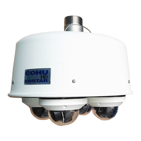
Eoptis MAIA M2 Instruction manual

MAIA M2
The multispectral camera
Quick User Guide
Rev.1.01 - 07/2019

Disclaimer
The information in this document is provided solely in connection with the product and a reasonable effort has been
made to have it accurate and reliable, however, we do not assume any liability whatsoever for the accuracy and
completeness of the above information. The manufacturer reserves the right to make changes, corrections,
modifications or improvements to this document, and to the products and services described herein, at any time and
without notice. No representations or warranties, either express or implied, of merchantability, fitness for a particular
purpose or of any other nature are made hereunder with respect to information/specification or the products to which
information refers and no guarantee with respect to compliance to the intended use is given. In particular, this also
applies to the stated possible applications or areas of applications of the product.
The customers are responsible for the appropriate, safe and legal use, processing and handling of our products.
Manufacturer
This product is manufactured in Italy by Eoptis Srl.
Life-support policy
The product is not designed for use in life-support appliances, devices or systems where malfunction of these products
can reasonably be expected to result in personal injury. Customers using or selling these products for use in such
applications do so at their own risk, and agree to fully indemnify the manufacturer for any damages resulting from such
improper use or sale.
Copyright, Trademarks and IP
All of the materials in this document are protected by copyright and other laws of intellectual property. They are not
allowed to be copied, reproduced or modified for any use without the written permission of Eoptis.
Eoptis and the Eoptis logo are trademarks of Eoptis Srl.
SAL Engineering and the SAL Engineering logo are trademarks of SAL Engineering Srl.
MAIA and the MAIA logo are trademarks of Eoptis Srl and SAL Engineering Srl.
Eoptis and SAL Engineering convey no patent, copyright, or other trade mark right to this product and do not assume
any liability for any patent and/or other trademark rights of a third party resulting from any use of the product.
The company names and other product names in this document might be the trademarks and trade names of their
respective owner(s), and are hereby acknowledged.
WorldView-2 is a commercial Earth observation satellite owned by DigitalGlobe. Sentinel-2 are a fleet of two identical
satellites developed by the European Space Agengy (ESA) to perform terrestrial observations. The Sentinel-2 and
WorldView-2 are trademarks of their respective owners. Neither DigitalGlobe nor the ESA are endorsing the MAIA
camera.
WEEE
This product should not be treated as household waste. Please ensure that this product is correctly disposed of, as
inappropriate waste handling can cause potential hazards to the environment and human health.
MAIA is a product of
SAL Engineering Srl
Via Godo Vecchia 23/a - 48026 Russi (RA) - Italy
Tel: +39 339 8364632
Email: info@salengineering.it
Eoptis Srl
Via Kufstein, 15 - 38121 Trento (TN) - Italy
Tel: +39 0461 260552
Email: info@eoptis.com
Copyright © 2016-2020 Eoptis Srl / SAL Engineering Srl - All rights reserved

MAIA M2
Quick User Guide
EOPTIS / SAL ENGINEERING
Page 3 of 15
MAIA M2
Rev.1.01 - 07/2019
Copyright © 2016-2019
Contents
1Introduction ......................................................................................................................................................... 4
2Operation of the camera....................................................................................................................................... 6
2.1 Optics, sensors and bands .............................................................................................................................. 6
2.2 Exposure........................................................................................................................................................ 8
2.3 Main connector.............................................................................................................................................. 9
2.3.1 Power supply........................................................................................................................................... 9
2.3.2 I/Os and synchronism .............................................................................................................................. 9
2.3.3 Serial port for communication with controller.........................................................................................10
2.4 MicroSD card and image format ....................................................................................................................10
2.5 USB connectors.............................................................................................................................................10
2.6 Images acquisition.........................................................................................................................................10
2.7 ACQ e LEDs buttons.......................................................................................................................................10
2.8 Front led .......................................................................................................................................................11
2.9 Internal clock ................................................................................................................................................11
2.10 Names and features of the image files........................................................................................................11
2.11 Mechanics and fixing..................................................................................................................................12
3Image processing software ..................................................................................................................................13
4Technical features................................................................................................................................................14
5Revision history ...................................................................................................................................................15

MAIA M2
Quick User Guide
EOPTIS / SAL ENGINEERING
Page 4 of 15
MAIA M2
Rev.1.01 - 07/2019
Copyright © 2016-2019
1INTRODUCTION
MAIA M2 is the low-cost modular multispectral camera, which can be expanded by adding other modules, thus creating
an extremely compact sensorsmatrix. A very large set of the main multispectral indices can be obtained using only three
modules. MAIA-M2 can also operate autonomously and is the smallest and lightest dual-sensor camera available on the
market. It is ideal for use on aerial and terrestrial vehicles (APR, drones, rover), particularly suitable for manufacturers,
operators and integrators operating in the field of precision agriculture and environmental monitoring.
MAIA is developed in Italy by Eoptis in collaboration with SAL Engineering and Bruno Kessler Foundation.
Each MAIA M2 camera is equipped with two 1.2Mpix CMOS sensors, with global shutter and high sensitivity, which
allow you to acquire stable and sharp images up to 1 shot per second. Each sensor is coupled with a higher quality
bandpass filter, which precisely defines the range of wavelengths of light that will be detected. The user can draw on a
vast portfolio of filters covering the visible (VIS) and near infrared (NIR) region to generate the known agronomic indices
and explore emerging applications. One of the two MAIA-M2 sensors can be in color, thus creating a 4-band camera of
minimum size.
MAIA M2 is able to capture images in free-run mode with fixed shutter frequency of 1fps or in external trigger mode,
based on an electrical signal. To allow an external unit to know the exact moment of tripping, MAIA M2 generates a
strobe synchronism signal that can be used for applications with Post Processed Kinematic (PPK).
The optimal exposure time for each sensor is automatically calculated and the user can select the brightness of the
images on three levels, through the camera button.
Acquisition images and parameters are saved on the MicroSD card in lossless RAW format with depths of 8 or 12 bits
per pixel. The card is removable, but it is also possible to download the images by leaving it inserted and accessing it
through the USB interface.
Two or more MAIA M2 cameras can be connected together to create a sensors matrix, increasing the indices that can
be calculated exponentially. A serial interface and trigger / strobe signals allow you to synchronize the cameras through
the appropriate controller that can be purchased as an accessory, making them operate as a single entity.
The MAIA M2 camera has dimensions of only 34mm x 49mm x 46mm (including lenses and connectors) and weighs only
59g.

MAIA M2
Quick User Guide
EOPTIS / SAL ENGINEERING
Page 5 of 15
MAIA M2
Rev.1.01 - 07/2019
Copyright © 2016-2019
Figure 1: Main elements of the camera with size of mechanics and details of connectors.

MAIA M2
Quick User Guide
EOPTIS / SAL ENGINEERING
Page 6 of 15
MAIA M2
Rev.1.01 - 07/2019
Copyright © 2016-2019
2OPERATION OF THE CAMERA
2.1 OPTICS,SENSORS AND BANDS
The MAIA M2 camera has 2 1280 x 960 (1.2Mpix) sensors with global shutter function. The camera is available with:
·2 mono sensors, or
·1 mono sensor + 1 color sensor
The monochromatic sensors are coupled to a band-pass filter that precisely defines the range of wavelengths detected
by the sensor (band).
A sensor with 8mm focal length, f / # 2.0, field of view ~ 36º Horizontal, ~ 27º Vertical (full angle) is mounted on each
sensor. Depending on availability during production, various types of lenses can be mounted, with similar optical
performance but different dimensions. Figure 1 shows a type of lens as an example.
The available bands are listed in Table 1 and shown in Figure 2.
Band
Start WL
(nm)
Stop WL
(nm)
Center WL
(nm)
Bandwidth
(nm)
Colour
B1
395
450
423
55
Violet
B2
433
453
443
20
NViolet
B3
455
520
488
65
Blue
B4
458
523
490
65
SBlue
B5
525
575
550
50
Green
B6
543
578
560
35
NGreen
B7
580
625
603
45
Yellow
B8
630
690
660
60
Red
B9
650
680
665
30
NRed
B10
698
713
705
15
H RedEdge
B11
705
745
725
40
RedEdge
B12
733
748
740
15
L RedEdge
B13
773
793
783
20
H NNIR
B14
750
820
785
70
H NIR
B15
785
900
842
115
W NIR
B16
855
875
865
20
L NNIR
B17
825
950
888
125
L NIR
RGB
-
-
-
-
RBG
Tabella 1. Bands available for MAIA M2.
6

MAIA M2
Quick User Guide
EOPTIS / SAL ENGINEERING
Page 7 of 15
MAIA M2
Rev.1.01 - 07/2019
Copyright © 2016-2019
Figure 2. Bands available for MAIA M2.

MAIA M2
Quick User Guide
EOPTIS / SAL ENGINEERING
Page 8 of 15
MAIA M2
Rev.1.01 - 07/2019
Copyright © 2016-2019
The choice of the pair of filters for the MAIA M2 camera is usually related to the type of indices to be calculated
according to the type of application. The models offered with the relative obtainable indices are described in Table 2.
Model
Bands
Main indices
Other indices
M2-V01
B1
B5
PPR
Plant Pigment Ratio
CTR6
M2-V02
B1
B8
NPCI
Normalized Pigment Chlorophyll
Index
IO, CTR1, LIC2, SRPI
M2-V03
B1
B11
WV-BI
Worldview Built-Up Index
WV-NHFD
M2-V04
B1
B15
BWDRVI
Blue-Wide Dynamic Range
Vegetation Index
WV-VI
M2-V05
B3
B5
PRI
Photochemical Reflectance
Index
BGI, CRI1
M2-V06
B3
B8
BRI
Blue Red Pigment Index
IOR
M2-V07
B3
B11
CRI2
Carotenoid Reflectance Index 2
M2-V08
B3
B15
BNDVI
Blue Normalized Difference
Vegetation Index
PSSRC1, PSSRC2,
PSNDC1
M2-V09
B5
B8
PVR
Photosynthetic Vigour Ratio
NGRDI, DSWI-4, GI
M2-V10
B5
B11
ARI
Anthocyanin Reflectance Index
M2-V11
B5
B15
GNDVI
Green Normalized Difference
Vegetation Index
PBI, GOSAVI, GSAVI,
RARS, GRVI, GCI
M2-V12
B7
B15
CTR3
Simple Ratio Carter 3
M2-V13
B8
B11
NDVIRedEdge
Normalized Difference
Vegetation Index Red Edge
FR, FR2, CTR4
M2-V14
B8
B15
NDVI
Normalized Difference
Vegetation Index
RDVI, TDVI, WDVI,
WDRVI
M2-V15
B11
B15
NDRE
Normalized Difference Red Edge
Index
NDCHL, RRI
M2-V16
RGB
B15
NDVI* GNDVI*
BNDVI* SAVI*
Immagine a
colori
*con Rosso/Verde/Blu a banda
larga
Table 2. MAIA M2 models with realted combinations of bands and multispectral indices.
2.2 EXPOSURE
The camera works in self-exposure trying to keep the average image value constant at target value despite
environmental variations. To do this, the exposure times are setted independently for each sensor. The exposure target,
common to the two sensors, can be set between three predefined values using the button on the camera. The default
values are 0.15, 0.20 or 0.25, with 0.20 set by default. These values are to be considered as the average brightness of
the image on a scale from 0 to 1, where in 0 there is a completely dark image and in 1 there is a completely saturated
image (all pixels with value 255 if in 8 bits or 1024 if in 12 bit). In the case of 0.20, for example, the average value of the
image will be around 51 codes (8 bits) or 205 codes (12 bits). The image will appear visually underexposed in its entirety
but this allows you to keep information even for any particularly bright areas that should appear in the image, occupying
only a marginal part.
The exposure algorithm requires a certain number of images to converge, depending on scene. In external trigger mode
the images are acquired only in the presence of triggers and therefore the first ones may not be correctly exposed.

MAIA M2
Quick User Guide
EOPTIS / SAL ENGINEERING
Page 9 of 15
MAIA M2
Rev.1.01 - 07/2019
Copyright © 2016-2019
2.3 MAIN CONNECTOR
The main connector supplies power to the camera and contains connections for I / Os and communication with
the controller.
The main connector on the board is a 5x2 pole 2.54mm pitch (CNCTech 3020-10-0300-00). For the flat cable
connector, it is recommended to use the IDC socket of the CNCTech 3030-10-0103-00 with retention. Alternatively, it is
also possible to use component 3030-10-0102-00 without retention.
The main connector pinout, shown in Figure 1, is described in Table 3.
Pin
Net
1
VDC
2
VDC
3
Out 1 - STROBE
4
Out 2 - Reserved
5
Serial TX –Reserved
6
Serial RX - Reserved
7
In 1 - FREERUN
8
In 2 - EXTTRIG
9
Gnd
10
Gnd
Table 3. Pinout of the main connector.
2.3.1 POWER SUPPLY
When the camera is mounted on a drone it is powered at 5VDC, from the main connector via the VDC and GND pins.
The 4-9V range is tolerated. The average consumption of the camera is 450-500mA at 5V. The power supply unit must
guarantee at least 1A inrush.
It is appropriate to leave plenty of free space around the camera and ensure an air flow for dissipation.
In the laboratory, for SD access and image transfer, the camera can be powered directly from the USB port. To guarantee
compatibility with the 500mA max of the USB standard, in this mode it is only possible to access the SD card and the
other camera functions are inhibited.
There is no power button, when the camera is powered, it starts automatically.
2.3.2 I/OS AND SYNCHRONISM
The camera can be synchronized with external devices using the following pins:
• 1 FREERUN input: when high, the acquisition starts in free-run mode at 1fps or the camera saves an image every
second. In this state the pressure of the ACQ button is ignored and the acquisition stops only by lowering the pin.
When low, you are in external trigger mode, i.e. the camera is sensitive to pulses on the EXTTRIG pin. If it is not
driven by an external device, this pin is low by default.
• 1 EXTTRIG input: the camera acquires an image at each rising edge on this pin, up to a maximum of 1fps. This pin
is ignored if the acquisition is started with the ACQ button or when the FREERUN pin is high. If you do not intend
to use this signal, leave the pin disconnected.
• 1 STROBE output, which emits a high pulse of 100ms duration each time an image is acquired. The rising edge
coincides with the start of integration by the sensors. The pin is driven by a push-pull driver and no external pull-
up resistance is needed.
All I / Os have 3.3V voltage and are tolerant for 5V at the input. The thresholds for the high level inputs are at 2.0V and
the low one at 1.3V. The outputs can supply or absorb a current of max 20mA.

MAIA M2
Quick User Guide
EOPTIS / SAL ENGINEERING
Page 10 of 15
MAIA M2
Rev.1.01 - 07/2019
Copyright © 2016-2019
See also section 2.6 Image acquisition for more details on the use of EXTTRIG and FREERUN signals.
2.3.3 SERIAL PORT FOR COMMUNICATION WITH CONTROLLER
On the main connector there is a serial port, which allows you to communicate with the controller via point-to-point
connection. The use of this interface is reserved.
2.4 MICROSD CARD AND IMAGE FORMAT
The camera saves the images in proprietary RAW format, at max 1fps on a microSD card. The color sensor saves 16 bit
RGB 4:6:4 already debayered. The monochrome sensor can be set to 8 or 12 bits.
The SD card must be removed and inserted ONLY with the camera turned off, i.e. the camera must not be connected
via USB to a PC or other external device nor must there be power from the main connector.
The camera supports 32GB microSD, with FAT32 formatting and 64k clusters (it is the default value used by Windows
for formatting this type of media). The card must be class 10 U3. The following models have been validated:
• Kingston Gold 32GB
• SanDisk Extreme Pro 32GB
• Samsung Pro Plus 32GB.
Operation with other cards of similar or higher specifications is generally possible but not guaranteed. The use of
capacities beyond 32GB is not recommended.
2.5 USB CONNECTORS
The camera has a USB2.0 connector for transferring the images saved on the SD to the PC, which will see the SD as an
external drive. Access to the card is made by connecting the camera to the PC with a USB A / Micro-B cable. It is not
recommended to power the camera simultaneously from USB and the main connector. The content of the SD is made
visible to the PC when connected. With the USB connection active, the other camera functions are inhibited.
When the camera is powered by USB, two LEDs, indicating the exposure level, flash.
2.6 IMAGES ACQUISITION
There are two ways of acquiring images, alternatives to each other:
• Continuous (or Freerun): the camera acquires 1fps images
• With external trigger: the camera acquires an image at the rising edge of the EXTTRIG trigger signal. The time
separation between two successive triggers must be greater than or equal to 1s. The exposure of the image
begins typically within 0.3ms from the trigger front.
In both cases, the acquisition takes place simultaneously from the two sensors. The two modes are managed through
the button and the FREERUN and EXTTRIG pins of the connector.
2.7 ACQ E LEDS BUTTONS
The ACQ button allows you to:
• Start and stop the Freerun acquisition mode
• Adjust the bit depth of monochrome images (8 or 12 bits)
• Adjust the exposure target between three levels (0.15, 0.20, 0.25)
To start the freerun acquisition, press the button quickly. When the freerun acquisition has been started with the
button, it is necessary to press the button again to stop it. Any events on the EXTTRIG and FREERUN inputs are ignored.
To set the parameters, keep the button pressed for 3s, until the Bit LED flashes. Press the button to move the led to the
desired setting. Confirm by holding the button for 3s. The configuration moves to the exposure level and the Exp LED
flashes. Set to the desired level by pressing the button. Exit the configuration mode by holding the button down for 3s.

MAIA M2
Quick User Guide
EOPTIS / SAL ENGINEERING
Page 11 of 15
MAIA M2
Rev.1.01 - 07/2019
Copyright © 2016-2019
The settings for the bit depth and the exposure target are kept when the camera is restarted and are visible on the LEDs
next to the button. During the setting of the parameters, the image acquisition is suspended. In order to set the
parameters it is necessary that there are no acquisitions in progress, i.e. that the FREERUN pin is low and that no triggers
are sent.
2.8 FRONT LED
The two-color LED visible on the front part of the camera indicates the presence of the power supply, the acquisition
status and any errors.
Camera status
LED status
Camera OFF
OFF
Camera ready to acquire images
GREEN
Red pulse at any image acquired
RED PULSE
Memory full
RED
Error. Ex.: starting acquisition without SD card or camera receiving too frequent
triggers.
RED FLASH
Table 4. Front LED status.
2.9 INTERNAL CLOCK
The camera has an internal clock, powered by battery, which is used to attribute the time of saving the images on the
SD card. The clock is factory adjusted to UTC time. Battery life is estimated to be over 10 years from the moment of
production and its replacement requires the camera to return to the factory.
2.10 NAMES AND FEATURES OF THE IMAGE FILES
The camera saves the image captured by the two sensors on the SD card in a single uncompressed file, with the ".Raw"
extension. The file format is a proprietary raw file, for which decoding it is recommended to use the supplied software.
The file name is constructed differently depending on whether the acquisition takes place in freerun mode or with
external trigger and a part of the name can be attributed by any external controller to synchronize the images with the
GPS logger. The files are placed in a folder named yyyymmdd (year, month, day), created when a new acquisition session
is activated.
An acquisition session begins with one of these events:
• The freerun mode is activated (by pressing the ACQ button or the FREERUN signal goes high)
• The camera receives the first trigger while the FREERUN signal is low (= external trigger mode enabled)
A subfolder with the name hhmmss (hours, minutes, seconds) is created in the session folder, which contains a
maximum of 1000 files. Exceeding 1000, another is created with new hhmmss.
The file name is in 8.3 format with the syntax yyyyyxxx.raw, where:
• xxx is a progressive 000-999 assigned by the camera to each save
• yyyyy is a value that in external trigger mode can be set by the controller by sending it to the serial line
immediately after each trigger pulse (from 00001 to 65535). If not received within the set times, it is set to 00000.
In freerun mode it is fixed at 00000.
When the camera operates in freerun mode in the absence of controllers and the acquisition takes particularly long
(over 16 minutes) to exceed 1000 files, the names of the files contained in the subfolders into which they are divided
are the same folder by folder. It is therefore necessary to be careful when copying the files to the PC and maintaining
the folder structure to avoid overwriting.
The size of the file varies according to the configuration of the sensors and the bit depth chosen.

MAIA M2
Quick User Guide
EOPTIS / SAL ENGINEERING
Page 12 of 15
MAIA M2
Rev.1.01 - 07/2019
Copyright © 2016-2019
Camera configurations
8 bit
12 bit
2 mono-chromatic sensors
2.5MB
4.8MB
1 mono-chromatic sensor + 1 RGB
3.7MB
4.8MB
Tabella 5. File size according to the cmaera configuration and bit depth.
2.11 MECHANICS AND FIXING
On the front of the camera there are 2 M2.5 holes, 3mm deep to fix the camera to a support. The support must ensure
adequate air circulation to allow heat dissipation.
If several modules are used side by side, it is important to align the modules in the best way so that they frame the same
scene and it is essential that the support ensures a rigid coupling that keeps the relative position between the modules
and the orientation of the view axes fixed. In the absence of this requirement, the image co-registration cannot be
completed.

MAIA M2
Quick User Guide
EOPTIS / SAL ENGINEERING
Page 13 of 15
MAIA M2
Rev.1.01 - 07/2019
Copyright © 2016-2019
3IMAGE PROCESSING SOFTWARE
Image processing can take place with MultiCam Stitcher Pro software of the 9-band MAIA camera, which allows you to
generate the image recorded on the various bands, also acquired from different MAIA M2modules. For the functionality
of the software, please refer to the User Guide of 9-band MAIA. Radiometric correction features are not currently
supported.
The use of the MultiCam Stitcher Pro software with images of the MAIA M2 requires an adaptation of the file, through
the use of the MAIA M2 Converter software. This software loads the images of up to 3 MAIA M2 modules and combines
them into a file compatible with the MultiCam Stitcher Pro. The change requires the presence of the geometric
calibration file of the various modules (.cal) and the .ini file containing the allocation rules . It is recommended not to
modify these files. To use, follow these steps:
1. Copy the images from the SD card to the PC, preserving the folder structure. It is recommended to process one
acquisition session at a time.
2. Run the software.
3. Choose the folder containing the files of each module. The characteristics of each module will be highlighted in terms
of serial number and bands and it will be possible to operate on the modules defined by the .ini file.
4. Choose the destination folder for the files.
5. Process the files in the destination folder, as required by the MultiCam Stitcher Pro software.

MAIA M2
Quick User Guide
EOPTIS / SAL ENGINEERING
Page 14 of 15
MAIA M2
Rev.1.01 - 07/2019
Copyright © 2016-2019
4TECHNICAL FEATURES
Campo
Valore
Sensors
2 sensors CMOS 1.2Mpix (1280x960) with high sensitivity global shutter
2 mono-chromatic sensors or 1 mono-chromatic + 1 RGB sensor
Optics
Geometric calibration of each lens
Focal lenght 8.0mm, f/# 2
Aperture: 36° horizontal, 27° vertical, 44° diagonal
Ground sampling distance (GSD): 3 cm*
Field of view (FOV): 45m x 34m *
* at height above ground level of 75 m
Exposure
Automatic, with possibility to set brightness on 3 levels
Acquisition
Single shot or continuous, with external trigger or at fixed frequency
Simultaneous shot for the two sensors up to 1fps
Images
RAW 8 - 12bits per pixel
File size: 2.5MB to 4.8MB, based on image format
Multi-layer / multi-band TIFF post-processing
Storage
Micro-SD class 10 U3 up to 32GB
Up to 12.000 images, equivalent to 3h acquisition
Interfaces
USB2.0 for downloading images
Trigger input and Strobe output for synchronism
Button or pin for input to start or stop the acquisition
Button to sett bits for pixels and image brightness
Serial port for connection of external controller
Size and weight
49mm x 34mm x 23mm (~46mm including lenses and connectors)
59g
Power supply
5-9VDC, 1A peak, ~2.5W typical
Ambient conditions
Operaional temperature 0-40°C
Operationl humidity 20-80% RH without condensation
Protection IP50
With a view to continuous product improvement, we reserve the right to change the specifications at any time without
notice.

MAIA M2
Quick User Guide
EOPTIS / SAL ENGINEERING
Page 15 of 15
MAIA M2
Rev.1.01 - 07/2019
Copyright © 2016-2019
5REVISION HISTORY
The User is recommended to check if this document applies to its camera, according to the Serial Number.
Version
Date
Valid for SN
Notes
Rev.1.00
08.2018
1826xxxx
Introductory release
Rev.1.01
07.2019
All
Global update of content for public release
Table of contents
Popular Digital Camera manuals by other brands
Olympus
Olympus FE 115 - Digital Camera - 5.0 Megapixel Manuel Avancé

Minolta
Minolta TC-1 instruction manual
Kodak
Kodak M753 - EASYSHARE Digital Camera Getting started guide
Panasonic
Panasonic LUMIX DC-FZ80 owner's manual

Lenovo
Lenovo Mirage Camera VR-4501F quick start guide

Samsung
Samsung SL35 - Digital Camera - Compact user manual
