EOS Mill Wheel Mini Planning guide

Druck-Nr. 29344338en / 13.21
EN Assembly and operating instruction
EOS Mill Wheel Mini
for Mill-Sauna

2EN
English
Table of Contents
General information ...................................................................................................................................3
General safety precautions ......................................................................................................................4
Delivery scope ..............................................................................................................................................5
Important Notes...........................................................................................................................................6
Installation......................................................................................................................................................7
Align mill .................................................................................................................................................7
Install Cascade.......................................................................................................................................7
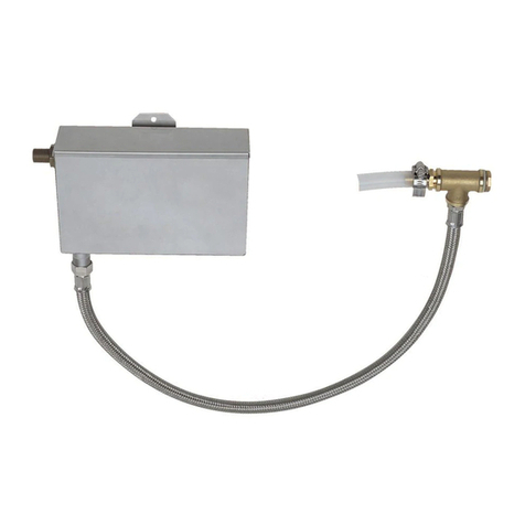
Install Water Tank .................................................................................................................................8
Set up Fixed Water Connections ......................................................................................................... 10
Set up Connection Fixed Water Connection- Water Tank................................................... 10
Connect Fixed Water Connection with Water System On-Site.. ....................................... 10
Installation and Connection of Control Unit................................................................................... 12
Electric connection of the display ..................................................................................................... 13
Mounting instructions for the remote control button (optional ltem no. 94.4087)........ 13
Wall mounting.................................................................................................................................... 13
Electric connection of the button .............................................................................................. 14
Start - up ...................................................................................................................................................... 15
Maintenance............................................................................................................................................... 16
Retightening the Toothed Belt..................................................................................................... 16
Dimensions ................................................................................................................................................. 17
Service Adress:........................................................................................................................................... 18
General Terms and Conditions of Service........................................................................................ 19

Please note that an optimal interaction be-
tween sauna cabin, sauna heater and sauna
control unit is mandatory for a pleasant sauna
climate in your cabin. With this high-quality
sauna control unit you can “operate“ your sau-
na system, and thanks to the many individual
programming options, surely you will quickly
nd the setting which suits you best.
Perception in the sauna is very subjective,
therefore, it really requires your own percep-
tion or that of your family to nd the most suit-
able settings.
The control units are supplied with the preset
typical climate values for a classic Finnish sauna
or for models with humidity control, as well as
for a sauna with humidity operation.
The following operating instructions describe
how to pre-select “your“ climate in the cabin.
Read these instructions carefully, so that you
General information about
sauna bathing
Preface
quickly and easily nd your way though the
programming process. Please note the varia-
tion in temperatures in the cabin while sauna
bathing. The hottest area is directly below the
cabin ceiling, whereas there is a steady temper-
ature gradient towards the oor of the cabin.
Inversely, the relative humidity is lowest direct-
ly below the cabin ceiling and the highest by
the cabin oor.
For safety reasons the temperature sensor with
the overheat safety shutdown is located on the
cabin ceiling above the heater, as this is usually
the hottest area in the cabin.
Thus, there will always be temperature varia-
tions between the temperature sensor of the
control unit and the thermometer in the cabin.
For example, when pre-setting the cabin tem-
perature to 100 °C, the thermometer inside the
cabin may show 85 °C - 90 °C. This is in accord-
ance with the typical climate inside the cabin.
Only use sauna-suitable (up to 140 °C temper-
ature-resistant) cabin lights. Always pay atten-
tion to hygiene. Always use hand- or bathing
towels to avoid getting perspiration on the
wood.
For control units with vaporizer connection
(optional), we recommend to reheat or dry the
cabin after each humid operation, in order to
protect your cabin from possible damage due
to the humidity mode. In addition, in poorly
ventilated rooms, a ventilation fan can be used
to remove the used moist air.
To avoid drafts, you should avoid using any
ventilation system while sauna bathing. It
should only be used if recommended by the
cabin manufacturer.
Dear customer,
you have purchased a high-quality electronic
device with which you will enjoy your sauna
& steam bath for many years to come. This
device was designed and inspected according
to the current European safety standards and
manufactured at the factory in accordance with
the quality management standard DIN EN ISO
9001:2015.
This detailed installation and operation manual
has been prepared for your information. Pay
particular attention to the important notes and
the information on electrical connection.
We wish you a restorative and eventful wellness
experience.
3
EN

General safety precautions
• This device may be used by children (age
8 and above) and by persons with reduced
physical, sensory, or mental disabilities, or
inadequate experience and knowledge,
if they are supervised or if they have re-
ceived adequate instructions in how to
use the device safely and understand the
associated risks.
• Children must be supervised to ensure
they do not play with the unit.
• Children and persons who have not re-
ceived proper instruction must not clean
or service the system.
• ATTENTION: It is forbidden to install
the control box in a closed switch cabinet
or behind a wooden panelling!
• The electrical installation may only be
done by a qualied electrical technician.
• You must comply with the regulations of
your power supply company and applica-
ble VDE regulations (DINVDE 0100).
• WARNING: Never attempt repairs or
installations yourself, as this could result
in serious injury or death. Only a qualied
technician may remove the housing cover.
• Please note the dimensions in the instal-
lation instructions, especially when in-
stalling the temperature sensor. The tem-
perature above the heater is critical for the
temperature setting. The temperature can
be held within operating parameters and
a minimal deviation at the bench level of
the sauna cabin can be achieved only if the
device is installed correctly.
• The device may only be used as intended
as a control unit for sauna heaters up to 9
kW (up to 36 kW when combined with a
power extension unit).
• Completely disconnect the control unit
from the electrical circuit, i.e. ip all circuit
breakers or the main circuit breaker during
each installation or repair.
• Please note the safety and installation
information from the sauna heater man-
ufacturer.
• Make sure to observe the specications
and instructions of the sauna cabin man-
ufacturer.
• ATTENTION: For control units with
remote control functions*, a protection
against switching on if the heater is cov-
ered is required. (use the suitable cover
protection rail or another safety device).
*Remote control = setting up, controlling or adjust-
ing a unit by a command that can be given out of
view of the unit by means of transfer media such
as telecommunication, audio technology or bus
systems, this also includes weekly timers. (from EN
60335-1)
4EN

Attention!
Dear customer,
according to the valid regulations, the
electrical connection of the sauna heater
and the control box has to be carried out
through the specialist of an authorized
electric shop
We would like to draw your attention that
in case of a warranty claim, you are kindly
requested to present a copy of the invoice
of the executive electric shop.
When designing the sauna cabin, en-
sure that the external exposed glass surfaces
may only reach a maximum temperature of
76 °C. If necessary, protective features need
to be tted.
Inspect the sauna cabin before each
use! In particular, ensure that no objects
have been stored on the sauna heater or the
IR-radiator, if applicable. Risk of re!
Attention!
Only the original spare parts may be used.
Any modication of the cables included in
the delivery can lead to malfunctions and
is not permitted.
Any unauthorized technical alteration
makes the product warranty void.
5
EN

6EN
At rst, check device for any damages and for
completeness. Any transport damages must im-
mediately be reported to the shipping company
or ask the rm responsible for delivery.
Scope of delivery includes:
- stand with column
- mill wheel
- water tank
- cascade
- control unit
- accessory bag
Important Notes
Inappropriate installation or usage could
cause re hazard! Please read this mounting
instructions carefully. Pay attention to all
measurement specications and the follow-
ing notes.
• The mill wheel must only be used in connec-
tion with the sauna heating device 34GM 18,
27 or 36 kW and the associated sauna control
unit.
• The device has been designed for a connec-
tion voltage of 230 V AC.
• The installation and the connection of the
device and other electrical utilities must
only be carried out by trained technicians.
Here, it is especially important to abide by
all protective measures necessary according
to VDE 0100v. §49DA/6 and VDE 0100 Part
703/2006-2
• The mill-sauna will be connected to the
power supply system via an earthed plug.
All connecting lines to be passed inside the
cabin must be suitable for an ambient tem-
perature of min 140 degree. We recommend
a silicone line. If single-wired lines will be
used as connecting lines, they must be pro-
tected by bendable metal pipes
• Please see that the start button is located
outside the cabin.
Prior to the installation of all individual components all protective foils
must entirely be removed.
Delivery scope

7
EN
Align mill
Put the stator with the column onto the desired
place and align horizontally by means of the
plate feet.
Use a water-level as supporting instrument.
Water-
level
Installation
Install Cascade
Cascade
Fastening
screws
Fig. 1
Fig. 2
Fig. 3
The cascade is screwed tight with 2 screws.
Attention!! Tighten the two screws rmly.

8EN
Non-contact run between cascade inflow
channel and mill wheel must be guaranteed
(approx. 3-5 mm tolerance).
Insert water tank sideways.
Install Water Tank
Note: Consider position of shovel.
91 cm
mill wheel
cascade
A
approx.
3-5 mm
A
Fig. 4
Fig. 6
Fig. 5
Mediate the water tank.

9
EN
Place the sauna heating unit (Herkules S60), as
shown next in front of the mill wheel as shown
91 cm
Inlet channel
To ensure an even distribution of the water even
distribution of the water, align the gutter with
the spirit level
Fig. 7
Fig. 8
Place the inlet channel over the stone basket,
so that the cascade ends centrally above the
channel.
The 4 noses on the underside of the inlet
troughnengage in recesses in the stone
basket frame. This prevents the gutter from
being inadvertently of the inlet channel is
impossible.

10 EN
Set up Fixed Water Connections
Important Notes:
The regulations of EN 1717 and/or DIN
1988 Part 4 must be attended. Appropriate
measures must be taken that prevent the wa-
ter from running back into the drinking water
pipeline. For this, especially pipe isolators or
system isolators are appropriate. If necessary,
ask your drinking water supply company or
your local sanitary expert.
Set up Connection Fixed Water Con-
nection - Water Tank
1 = T-piece
2 = Sealing
3 = Discharge plug
4 = Hose clip
5 = Silicone tube
6 = Armoured tube
Remove all specied parts from the accessory
bag and mount them according to the gure.
Now, using the sealing band theT-piece will be
screwed onto the ½" nipple on the underside
of the fixed water connection, whereas the
lock nut, including the inside sealing, will be
screwed onto the nipple on the water tank.
(2)
(3)
(4)
(5)
(1)
(6)
Connect Fixed Water Connection with
Water System On-Site.
Please note: Between xed water
system and xed water connection a
shut-o cock must be installed. In case the xed
water connection will not be used for any
length of time, the shut-o cock is to be closed.
Attention: Maximum operating
pressure 6 bar
Finished connection
Fixed Water Connection
- Water Tank
3/8" connec-
tion nipple
for fixed
connection
on site.
Fig. 9
Fig. 10

11
EN
The system may only be lled with water.
The water level in the water tank should be
between 70 and 110 mm.
Water level
70 - 110 mm
Fixed water connection 3/4"
Float
Seal 3/4"
The float (1) opens or closes the valve (2) to
ensure that the tank remains full.
The water level can be regulated by turning
the oat.
Fig. 12
Fig.13
150
180
65 (75*)
* mit Befestigungsbügel
(1)
(2)
Fig. 11

12 EN
Mount the control unit outside of the cabin.
To this end, open the housing and t to the
intended place with four screws.
Lay the fed line to the mill wheel
and connect it to the motor connection
on the rear of the mill wheel.
With the 4-wire line, we provide you with the
usage of two potential-free contacts (Signal
1 and signal 2). With these contacts, you can
switch installations at the place of installtion,
such as lights or ventilations up to a maximum
power input of 2.5 A.
Finally, insert the shockproof plug into a plug
and the mill wheel is ready for operation.
*) Signal 1 = wires 1 + 2
Signal 2 = wires 3 + 4
Remote control key
(optional)
Display terminal (op-
tional)
Mill drive
Output
Signal 1*
Signal 2
Mains supply
On/O switch
Programme switch
Mounting openings
Mounting openings
Taster/
blau/blue
rot/red
weiß/white
STANDARD
3
~
M
1 2 3
1 2 4
230V~
Schaltbox Steuerung/
3
Netz/mains
Licht/light
Lüfter/fan
4
OPTIONAL
switch-key
4
switch box control
3
Installation and Connection of Control Unit

13
EN
Mounting instructions for the remote control button (optional
Item no. 94.4087)
• Children should be supervised to ensure
that they do not play with the unit.
• Protect the button from splash water
The button must only be installed
outside of the cabin. When using
the button inside the cabin, there is a
danger of burning.
Wall mounting
Preferably chose the outside wall of the cabin
for mounting. Observe the following instruc-
tions for mounting:
Cut the two adhesive tape strips supplied into
two equally long parts (40 x 20 mm).
Now t the two adhesive tape strips at the rear
of the button housing at the same distance.
Lay the feed line to the controls of the mill
and lead them through cable opening in the
control housing.
Insert the plug of the feeder in the planned
socket on the board inside the controls. Please
note that the xing nose ts into the planned
nut on the socket.
Electric connection of the display

14 EN
Electric connection of the button
Remove wire bridge
black+blue purple brown
Feeder line
Remote control button
Press the button housing with the affixed
adhesive tape against the wall in the desired
place of mounting.
Now pull the button back o again and press
the remaining adhesive tape strips down.
Then ax the button again and lead the con-
nection line to the controls

15
EN
1. Sample program with a running time of 30 minutes.
Start - up
Set the controls to the desired mode when switched o only
2
ON
1
Programme switch
2. Sample program with a running time of 45 minutes.
3. Sample program with a running time of 60 minutes.
ON
12
ON
12
4. Sample program with tracer circuit (Art.Nr. 944087)
Programme switch
Programme switch
Programme switch
Pause time
Steam shock time
Signal 1 (Light: "Attention Steam shock"
Signal 2 (Ventilator)
Elapsed time in minutes 24 1,5 1 0,1 0,3 1 0,1 0,3 1 0,1 0,3
Pause time
Steam shock time
Signal 1 (Light: "Attention Steam shock"
Signal 2 (Ventilator)
Elapsed time in minutes 39 1,5 1 0,1 0,3 1 0,1 0,3 1 0,1 0,3
Pause time
Steam shock time
Signal 1 (Light: "Attention Steam shock"
Signal 2 (Ventilator)
Elapsed time in minutes 54 1,5 1 0,1 0,3 1 0,1 0,3 1 0,1 0,3
Pause time
Pressing the
optional remote
switch-key
Steam shock time
Signal 1 (Light: "Attention Steam shock"
Signal 2 (Ventilator)
Elapsed time in minutes 1,5 1 0,1 0,3 1 0,1 0,3 1 0,1 0,3
ON
12
switch 1 = off
switch 2 = off
switch 1 = off
switch 2 = on
switch 1 = on
switch 2 = off
switch 1 = on
switch 2 = on

16 EN
Switch the mill wheel on using the ON/OFF
switch.
The programme procedure starts.
With programme 4 you start the infusion by
pressing the optional remote control button
at the desired time.
After every infusion, wait approx. 10 minutes
until the next infusion. Only then have the
sauna stones heated up properly.
Only switch the mill on when
the oven and sauna stones are
at operating temperature. This takes
approx. 45 minutes.
Note: With soft pressure the belt must only
be compressible for max 5mm.
Maintenance
Retightening the Toothed Belt
Fixing screws
Adjusting
screw
• At rst, loosen all 4 xing screws
• Then, stress toothed belt by means of the
adjusting screw.
• Finally, retighten all 4 xing screws.

17
EN
Dimensions
Wall distance: 100 mm
Safety grid
540
910
510
100
100
100
800
1500
855

Service Address:
EOS Saunatechnik GmbH
Schneiderstriesch 1
35759 Driedorf, Germany
Tel: +49 (0)2775 82-514
Fax: +49 (0)2775 82-431
www.eos-sauna.de
Please retain this address together with the installation
guide for further references.
To help us answer your questions quickly and compe-
tently please provide the information printed on the
type shield including the model, item no. and serial no.,
in all inquiries.
Equipment commissioning date:
____________________________
Stamp and signature of the authorized
electrician:
18 EN

General Terms and Conditions of Service
I. Scope
Unless otherwise agreed in writing in a specic case,
these terms and conditions of service shall apply to ser-
vice operations, including examining and repairing com-
plaints. All our existing or future legal relationships shall
be governed solely by the following terms and condi-
tions of service. Our recognition of any conicting terms
and conditions of the Ordering Party shall be conditional
upon our having given our express written consent to
their applicability. We hereby expressly object to any
terms and conditions of the Ordering Party contained
in its General Terms and Conditions of Business or order
conrmation. If order conrmations or deliveries are ac-
cepted without reservation, this shall not be deemed to
constitute recognition of such terms and conditions. Any
ancillary agreements or amendments must be conrmed
in writing.
II. Costs
The Ordering Party shall bear the following costs in con-
nection with the service operation:
• De-installation/installation and electrical works (con-
nection / disconnection).
• Transportation, postage and packaging.
• Function testing and troubleshooting including in-
spection and repair costs.
There shall be no third-party billing.
III. Obligations / Ordering Party‘s coopera-
tion
The Ordering Party shall provide free-of-charge assis-
tance to the manufacturer in carrying out the service
operation.
In the case of a warranty claim the manufacturer shall
provide the required replacement parts to the Ordering
Party free of charge.
IV. Service visit by the manufacturer
In the event that it is essential that a manufacturer em-
ployee carry out the service operation on site, this must
be agreed in advance. Where the main reason for the ser-
vice call is not the fault of the manufacturer, any costs
incurred shall be recharged to the Ordering Party after
the service visit and shall be paid as per agreed payment
terms.
V. Liability
The manufacturer shall assume liability in accordance
with the currently applicable statutory regulations. The
packaging for all of our products is designed for the ship-
ping of individually packed goods (pallet). We expressly
point out that our packaging is not suitable for individual
shipments via parcel post. The manufacturer shall accept
no liability for damage incurred as a result of improper
packaging in an individual shipment.
VI. Manufacturer‘s Guarantee
The manufacturer‘s guarantee shall apply only in the
event that installation, operation and maintenance have
been carried out in accordance with the manufacturer‘s
specications contained in the installation instructions
and instructions for use.
• The guarantee period shall commence from the date
on which proof of purchase is provided and shall be
limited, in principle, to 24 months.
• Guarantee services shall be performed only if the orig-
inal proof of purchase relating to the equipment can
be presented.
• Any and all guarantee claims shall become void if
modications are made to the equipment without the
manufacturer‘s express consent.
• Any guarantee claim shall likewise become void in
the case of defects that arise due to repairs or inter-
ventions made by unauthorized persons or due to
improper use.
• In the case of guarantee claims, the serial and article
numbers must be indicated together with the product
name and a meaningful description of the fault.
• This guarantee shall cover defective equipment parts,
with the exception of usual wear parts. Wear parts are,
among others, lamps, glass parts, heating elements
and sauna stones.
• Only original replacement parts may be used within
the warranty.
• Service visits by outside companies shall require a
written order to be issued by our service department.
• The equipment in question shall be sent to our service
department by the Ordering Party and at its expense.
• Electrical installation and connection works in the
event of service or replacement shall be carried out at
the Customer‘s expense and shall not be borne by the
manufacturer.
Complaints in respect of our products shall be reported
to the responsible authorized dealer and shall be exclu-
sively handled via the latter.
The manufacturers General Terms and Conditions of
Business, which can be found at www.eos-sauna.com/
agb, shall apply in addition to the foregoing terms and
conditions of service.
As of 08/2018
19
EN
Table of contents
Other EOS Water System manuals
Popular Water System manuals by other brands

Sidite
Sidite SR882 Installation and operating manual

Oase
Oase ProfiClear Premium TF-XL operating instructions

Viqua
Viqua Hi-Flo instruction sheet

Condair
Condair RO-A Service manual

Galletti
Galletti CSW T Installation, use and maintenance manual

Ecodyne Water Systems
Ecodyne Water Systems TB-RO Installation and operation manual

Aqualife
Aqualife WATER.IO Smart Water Bottle user guide

Rinnai
Rinnai Prestige Close Coupled Systems Operation & installation manual

123Filter
123Filter ED2000 manual

Spectra Watermakers
Spectra Watermakers Farallon 1800 Installation and operating manual

WaterGroup
WaterGroup E75TFC-3 Installation, operation and service manual

BWT
BWT BWTDWFK-TRIFLO manual