eove EO-150 User manual

Applies from S/N EO1X00120001S 100-23 rev DA_01/2020
EO-150 Ventilator
User Guide

2

3
Contents
................................................................................................................................................................ 1
Introduction ............................................................................................................................................ 6
Indications for use ............................................................................................................................... 6
Contraindications ................................................................................................................................ 7
Adverse Effects ................................................................................................................................... 7
Definitions ........................................................................................................................................... 7
Ventilator dependent patient warnings ............................................................................................. 7
General warnings and cautions .......................................................................................................... 8
Chapter 1 – Description of the EO-150 ventilator ................................................................................ 10
Front Panel ........................................................................................................................................ 10
Rear Panel ......................................................................................................................................... 11
Rear view of ventilator without housing .......................................................................................... 12
Ventilation module and docking station references......................................................................... 12
Menu Bar / Keyboard ........................................................................................................................ 13
Symbols Table ................................................................................................................................... 13
Chapter 2 – Operating Instructions for the EO-150 ventilator ............................................................. 16
Set Up Test ........................................................................................................................................ 16
Additional tests for alarms from ISO 80601-2-72: ............................................................................ 17
Turning on the device ....................................................................................................................... 18
Turning off the device ....................................................................................................................... 18
Starting and Stopping ventilation ..................................................................................................... 18
Using Stand-by mode ........................................................................................................................ 19
Turning on and off the docking station ............................................................................................. 20
The Home Screen .............................................................................................................................. 20
Navigating the Patient Screen and Menu ......................................................................................... 22
Navigating the Monitoring Menu ..................................................................................................... 23
Active alarm list ................................................................................................................................. 23
Accessing and using the Clinical Menu ............................................................................................. 24
Presets ............................................................................................................................................... 25
Presets Configuration ....................................................................................................................... 25
Circuit / Patient Configuration Menu ............................................................................................... 27
Changing ventilation mode ............................................................................................................... 27

4
Other screens .................................................................................................................................... 28
Chapter 3 - Patient circuit, power supplies and accessories configurations ........................................ 33
Patient Circuit options ...................................................................................................................... 33
Calibration ......................................................................................................................................... 34
Connecting circuit configurations ..................................................................................................... 36
Accessories Compatible with EO-150 ............................................................................................... 40
Attaching patient circuit accessories ................................................................................................ 40
Attaching an antibacterial filter ........................................................................................................ 40
Attaching a humidifier ...................................................................................................................... 41
Attaching oxygen .............................................................................................................................. 42
Attaching an FiO2 sensor ................................................................................................................... 43
Attaching a pulse oximeter ............................................................................................................... 43
Attaching a remote alarm ................................................................................................................. 44
Attaching EO-BAT9 ............................................................................................................................ 44
Power Connections ........................................................................................................................... 45
Connecting to mains power .............................................................................................................. 45
Running the ventilator on internal battery ....................................................................................... 45
Battery run time ................................................................................................................................ 47
Storing and recharging ...................................................................................................................... 48
Prepare the battery for long-term storage ....................................................................................... 48
Connecting to an external DC power source .................................................................................... 48
EO-150 Car lighter DC cable (Ref EO-CARCBL) - Instructions for use ................................................ 49
Connecting two power sources using the Y cable (EO-CPLPACK or EO-CPLPACKBOX): ................... 50
Mounting EO150 on trolley (KC072283) ........................................................................................... 52
Travelling with EO150 Ventilator, the Click-and-Go system ............................................................. 53
Using the Nomad Bag (no docking station) ...................................................................................... 53
Using the Transport bag .................................................................................................................... 54
Chapter 4 - Alarms ................................................................................................................................ 56
Alarms inhibition and pre-inhibition ................................................................................................. 57
Alarm priority .................................................................................................................................... 57
Troubleshooting Alarms .................................................................................................................... 58
Chapter 5 - Routine Cleaning and Maintenance ................................................................................... 61
Instructions for hygienic reprocessing at patient change ................................................................. 62
List of parts potentially contaminated by exhaled gas: .................................................................... 62

5
Servicing ............................................................................................................................................ 63
Maintenance Timetable .................................................................................................................... 63
Chapter 6 - Device information ............................................................................................................. 64
Technical specifications .................................................................................................................... 64
Physical Specifications ...................................................................................................................... 64
Ventilation Specifications ................................................................................................................. 64
Accuracy of ventilation settings ........................................................................................................ 71
Measurements uncertainties ............................................................................................................ 71
Monitored Parameter Specifications ................................................................................................ 72
Accuracy of monitoring data ............................................................................................................. 72
Power specifications ......................................................................................................................... 74
Environmental Specifications............................................................................................................ 74
Breathing system Specifications ....................................................................................................... 75
Software versions.............................................................................................................................. 75
Guidance and Manufacturer’s Declaration Electromagnetic Emissions & Immunity....................... 76
Standards compliance ....................................................................................................................... 80
Training and support ......................................................................................................................... 81
Limited warranty ............................................................................................................................... 81
Appendix A: Definitions .................................................................................................................... 82
Ventilation Setting Definitions .......................................................................................................... 82
Measured and calculated parameter definitions ............................................................................. 83
Other Definitions............................................................................................................................... 84

6
Introduction
The EOVE EO-150 ventilator provides mechanical ventilation for ventilator dependent and non-
dependent patients.
Patient circuit for ventilator dependent patients:
Double branch
Single branch with proximal flow
Leak ventilation circuit
Patient circuit for non ventilator dependent patients:
Double branch
Single branch
Single branch with proximal flow
Leak ventilation circuit
Applied parts are patient circuit components (not provided by EOVE).
EO-150 provides pressure and volume ventilation for adults and pediatric patients as prescribed by
an attending doctor.
Indications for use
The EO-150 ventilator device provides continuous or intermittent ventilation support for pediatric
and adult patients weighing at least 3.5kg (8lbs) who require mechanical ventilation.
The EO-150 device is intended to be used in home, institution, hospital and portable environments
for both invasive and non-invasive ventilation.
Patient and or caregivers are considered as operators (from IEC 60601-1 definition). They are
intended to safely perform the following operations (with appropriate mandatory training from the
homecare provider):
Start and stop device
Start and stop ventilation
Inhibit alarm sound
Switch presets
Change preference settings
Perform circuit replacement and circuit calibration
Patient and/or caregivers are not intended to:
Change clinical settings
Perform any maintenance operation
CAUTION
E0-150 ventilator is not for use with anaesthetic gases, and is not intended for use
as an emergency transport ventilator
WARNING
Do not use EO
-
150 ventilator in an MRI equipment or in a barotherapy equipments
A significant risk of
reciprocal
interference could be posed by specific investigation
or
treatment devices.
The EO
-
150 ventilator must not be serviced while in use on a patient
The EO
-
150 ventilator is not intended for use in oxygen enriched environment

7
The EO
-
150 ventilator is not intended for use with flammable anesthetics and neither for
use in conjunction with flammable agents.
Contraindications
Severe hypotension particularly with intravascular volume depletion
Pneumothorax or pneumomediastinum
After brain surgery or cranial trauma
Cerebrospinal fluid leak
Dehydration
Bullous emphysema
Adverse Effects
Dry nose or mouth
Eye irritation
Bloating
Gastric distension
Skin wound
Sinus discomfort
Definitions
WARNING
Indicates a condition that may endanger the patient or the device operator
CAUTION
Indicates a condition that may damage the device or equipment
Note:
Advice that makes operation of the device
more convenient or efficient
Ventilator dependent patient warnings
WARNING
An alternative means of ventilation should always be available for ventilator
-
dependent
patients. Failure to do this may result in patient injury or death.
A ventilator dependent patient should always be monitored by trained personnel.
For ventilato
r dependent patients, in case of failure of the principal ventilator and using
a stand-alone ventilation module (without docking station) as a backup device, the
backup ventilation module must be used immediately by pressing on the module keypad
buttons without inserting it in the docking station of the faulty ventilator. In any case of
failure, contact your technical assistance immediately after ensuring the patient is safely
ventilated with the backup device and wait for further instructions.
Ensure that the home AC mains supply and connections are safe and comply with the
applicable regulations. For ventilator dependent patients, consider using a back-up
power system. For safe and adapted solutions, refer to Battery Pack (EOBAT9) user
manual and to the section “Connecting two power sources with Y cable” below.
For ventilator dependent patients in mobility we strongly recommend not to use internal
battery as primary power source. It is mandatory to use an additional power source such
as EOVE Battery Pack (EO-BAT9) when the patient is moving away from an external
power source (AC or DC).
If a “BAT. CHARGE FAIL” or a “BATTERY FAIL” alarm triggers, the ventilator internal
battery needs to be changed. For ventilator dependent patients, contact your technical
assistance immediately after ensuring the patient is safely ventilated with the backup
device and wait for further instructions.

8
As the battery ages, the available capacity decreases. When the remaining battery
capacity is low, do not rely on the internal battery as the primary power supply and
contact your service provider.
When using the EO
-
150 as a backup ventilator, check and charge the internal battery
level regularly (recommended every month).
Some circuit and accessories conf
igurations (mainly in leak
pediatric configuration) with
high resistive pressure in the circuit could lead to ineffective "Disconnection alarm".
For ventilator dependent patient, "Disconnection alarm" must be tested after any
calibration, setting changes or circuit configuration change.
In case the disconnection alarm detection is not efficient, it is mandatory to set a VTI Min
alarm (leak configurations) or a VTI Max alarm (valve configurations) as a backup for
disconnection events covering.
General warnings and cautions
WARNING
The user and/or the patient must inform its service provider of any serious incident
occurred with the device. This information must be notified to EOVE and to competent
local authorities if necessary.
Read and
understand the entire manual before using the EO
-
150 ventilator
The EO
-
150 ventilator is a restricted medical device intended for use by qualified trained
personnel, under the direction of a doctor.
Use the EO
-
150 ventilator only as directed by a doct
or or healthcare provider.
Information in this manual does not supersede instructions given by the prescribing
doctor.
Install and configure the EO
-
150 ventilator in accordance with the instructions given in
this guide. Non-specialist operators or institutions encountering problems with set-up,
operation or maintenance should immediately contact their EOVE representative.
Verify the effectiveness of ventilation and alarms before connecting a patient to the
ventilator.
Handle the EO
-
150 ventilator and AC power supply with care during and after use
especially if ambient temperatures are high as some surfaces may become hot. Do not
leave the EO-150 ventilator in direct contact with the patient for extended periods of
time.
The EO
-
150 should be kept out of reach of children and domestic animals to ensure their
safety and the safety of the patient and to avoid damage to the ventilator and the
accessories.
The battery and all machine parts of the ventilator and accessori
es (including trolley)
should be disposed of appropriately, following correct regulations for waste
management in order to minimize the risk for the environment. They should not be
disposed of in household waste.
Ensure that the device and its power char
ger are placed in a way that allows an easy
disconnection from the mains.
Do not use the ventilator to an altitude higher than 3000 m, or out of the temperature
range 5°C-40°C. Using the ventilator out of these conditions can alter ventilation
performance and consequently cause patient death.
Do not supply the ventilator with a wheelchair battery unless this is mentioned in the
wheelchair user’s instructions or in the ventilator user’s instructions.

9
Ventilator’s accuracy can be degraded when using a nebulizer.
CAUTION
The EO
-
150 ventilator is not intended for use as an emergency transport ventilator.
Do not expose the EO
-
150 ventilator to excessive force, do not shake or drop.
If the ventila
tor or its power supply are dropped or mishandled, immediately discontinue
use and contact your EOVE representative.
Repairs and servicing should only be carried out by an authorized EOVE service
representative or a qualified and certified Service representative.
The airflow for breathing produced by the ventilator can be higher than the temperature
of the room by up to 6°C. Exercise caution if the ambient air in the room exceeds 35ºC.

10
Chapter 1 – Description of the EO-150 ventilator
Front Panel
1. Display screen
4. EO device housing unit
2.
Ventilation module
5. Inspiratory / Circuit Port
3. Proximal pressure, valve, and proximal flow connectors
6. Menu bar / keyboard
2
4
6
1
3
5

11
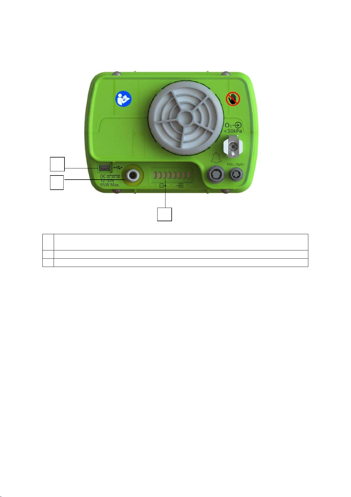
Rear Panel
1. Air inlet and hypoallergenic filter
5.
USB
-
1 port (data retrie
val)
2. DC
Power connector
6. O
2
input
3.
Docking station
Power
Button
7. FiO
2
/ SpO
2
connector
4. USB
-
2 port (maintenance only)
8. Remote Alarm connector
2
6
7
1
3
4
5
8
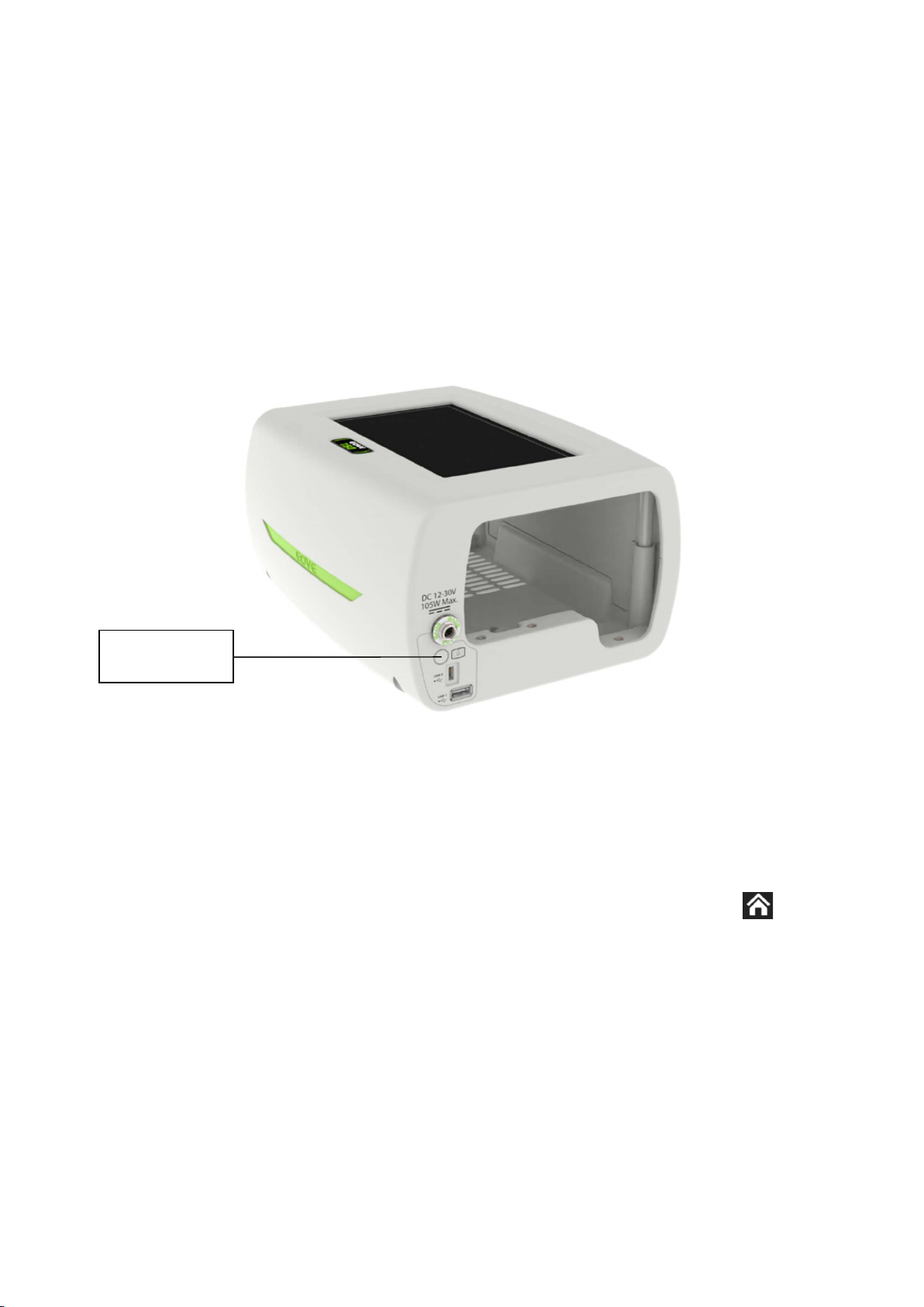
12
Rear view of ventilator without housing
1.
USB port (Do not use
-
limited to maintenance operations as described in the maintenance
manual)
2.
DC Car charger connection
3.
Connection to outer housing
Ventilation module and docking station references
EO-150 Complete ventilator: EO-150VNT
EO-1X0 Docking station reference: EO-DCK1SLT
EO150 Ventilator module reference: EO-VM150
1
2
3

13
Menu Bar / Keyboard
1.
Power source indicator
6.
ON / OFF switch
2. High priority alarm indicator
7.
Physiological alarm indicator
3. Technical alarm indicator
8.
Medium priority alarm indicator
4. Circuit alarm indicator
9.
Alarm reset
5. Ventilation start / stop
10.
Battery life indicator
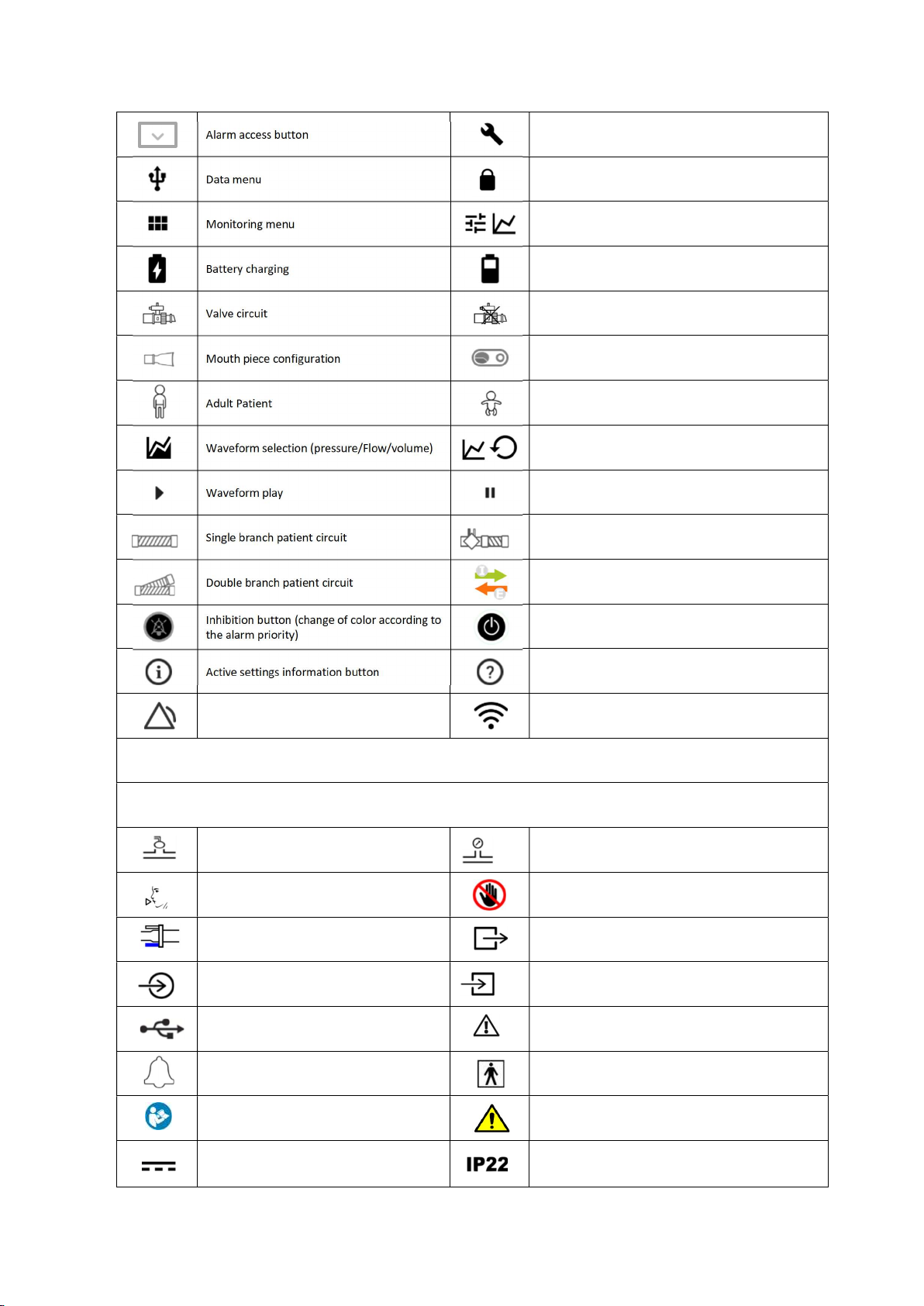
Symbols Table
The following symbols may appear either on your product or its packaging.
Keypad indicators / buttons
Alarm priority indicators and mute Button Patient Alarm indicator
Technical Alarm indicator Interface Alarm indicator
Battery level indicator AC/DC power indicator
On/Off button START/STOP ventilation button
Touch interface symbols
Ventilation start Ventilation stopping
Menu access button Preference menu
Return to Home Screen Calibration screen access
1
2
3
4
5
6
7
8
9
10
14
Maintenance menu
Clinical Mode locked
Clinical menu
Battery power indicator
Leak circuit
Proximal free configuration
Pediatric Patient
Waveform selection (normal / loop)
Waveform pause
Single branch patient circuit with proximal flow
Inspiration trigger (I) / Exhalation trigger (E) activation
symbols
Power off button
Help button
Active alarm (change of color according to the
alarm priority) Connected to a Wi-Fi spot
Device / packaging symbols
Exhalation Valve port Proximal Pressure Port
Inspiratory Port (to patient) Do not obstruct
Expiratory Flow port Connection ports
Oxygen inlet Connection port
USB connector Warning
Alarm repeater connection
Applied part BF type
Consult operating instructions
Battery replacement warning: Only
trained personnel can replace batteries
DC power inlet
International Protection Marking, IEC standard
60529. Protection against ingress of water and foreign
objects.

15
Date of manufacture This side up
Complies with European legal requirements
Manufacturer
High and low temperature limitations for
transport and storage Serial number
Should not be disposed of in household waste Product reference number
Keep dry Recyclable
Danger of fire if damaged Copyright
Fragile. Handle with care. Class II device
Humidity range for transport and storage
Docking station Power Button
Maximum weight for trolley (including
ventilator and accessories) Do not push (symbol for trolley accessory)
Medical Device Single patient, multiple use

16
Chapter 2 – Operating Instructions for the EO-150 ventilator
WARNING
Blocking the air inlet could lead to patient injury.
Keep machines clear of blankets, soft toys, and dust. Keep out of direct sunlight.
CAUTION
To prevent possible damage to the ventilator always place it on a flat, dry and stable surface.
To protect the device during transportation, always ensure that the EO-150 ventilator is
transported using the EOVE Transport bag, Nomad bag or Travel bag.
Always protect the device from water if used outdoors.
Set Up Test
Before using the EO-150 ventilator, perform the following Set Up test.
WARNING
If alarms do not sound during the Set Up test, do not use the ventilator.
CAUTION
Contact your healthcare provider or EOVE for assistance if any of the checks in the set up test
fail.
If the EO
-
150 has been returned after servicing, ensure it is clearly labelled as disinfected
before starting the set-up test or installing.
To perform a Set Up Test
During a first patient installation, it is recommended to check the correct operating status of the
device:
1.
Connect the device to the AC power source and turn it off.
2.
Check the condition of the device and accessories, and the condition of the patient’s circuit.
3.
Turn on the device (see next page). The device should sound and
the display screen should turn
on correctly.
4.
Disconnect the AC power source. The “AC power loss” alarm should trigger, and the medium
priority alarm indicator and the alarm reset button should flash. Press the reset alarm button to
stop the alarm.
5.
Connec
t the AC power source to the device. Two beeps should sound. Check that the power
source indicator LED is on the ventilation module, and that “AC” is displayed on the patient
interface.
6.
Perform a circuit calibration (see calibration on chapter 3).
Note:
Pressure and Flow sensors are tested during circuit calibration.
WARNING
If any of these steps fails, do not use the EO 150 ventilator. Contact your healthcare
provider or your Eove representative for a device checking.

17
WARNING
Some circuit and accessories configurations (mainly in leak
pediatric configuration) with
high resistive pressure in the circuit could lead to ineffective "Disconnection alarm".
For ventilator dependent patient, "Disconnection alarm" must be tested after any
calibration, setting changes or circuit configuration change.
In case the disconnection alarm detection is not efficient, it is mandatory to set a VTI Min
alarm (leak configurations) or a VTI Max alarm (valve configurations) as a backup for
disconnection events covering.
Additional tests for alarms from ISO 80601-2-72:
Low volume (Low VTE): Set the low VTE alarm to a value higher than the monitored VTE for 3
consecutive breaths or 10 s.
High pressure alarm: Bloc the test lung during inspiration for three consecutive breaths.
Obstruction (occlusion alarm): Bloc the inspiration outlet for two consecutive breaths or 5 s.
Hypoventilation (low rate alarm): Set the low rate alarm to a higher value than set rate and let
the ventilator running for 6 consecutive breaths.
Continuous positive pressure (PEEP alarm): Clamp the proximal pressure tubing in order to
obtain a pressure higher than set PEEP + 10 cmH2O during 6 consecutives breaths or 17 s.
High LEAK alarm (leak modes): Set the leak alarm max threshold to a higher value thant the
monitored value for 6 consecutive breaths.
18
Turning on the device
Ensure the device has been charged prior to use or connect to AC power or DC connector inlet.
1.
Insert AC connector into power inlet.
2.
Turn the screw lock clockwise to secure.
3. Device will turn on automatically. If starting on battery, press on front panel keyboard to
power on the ventilator.
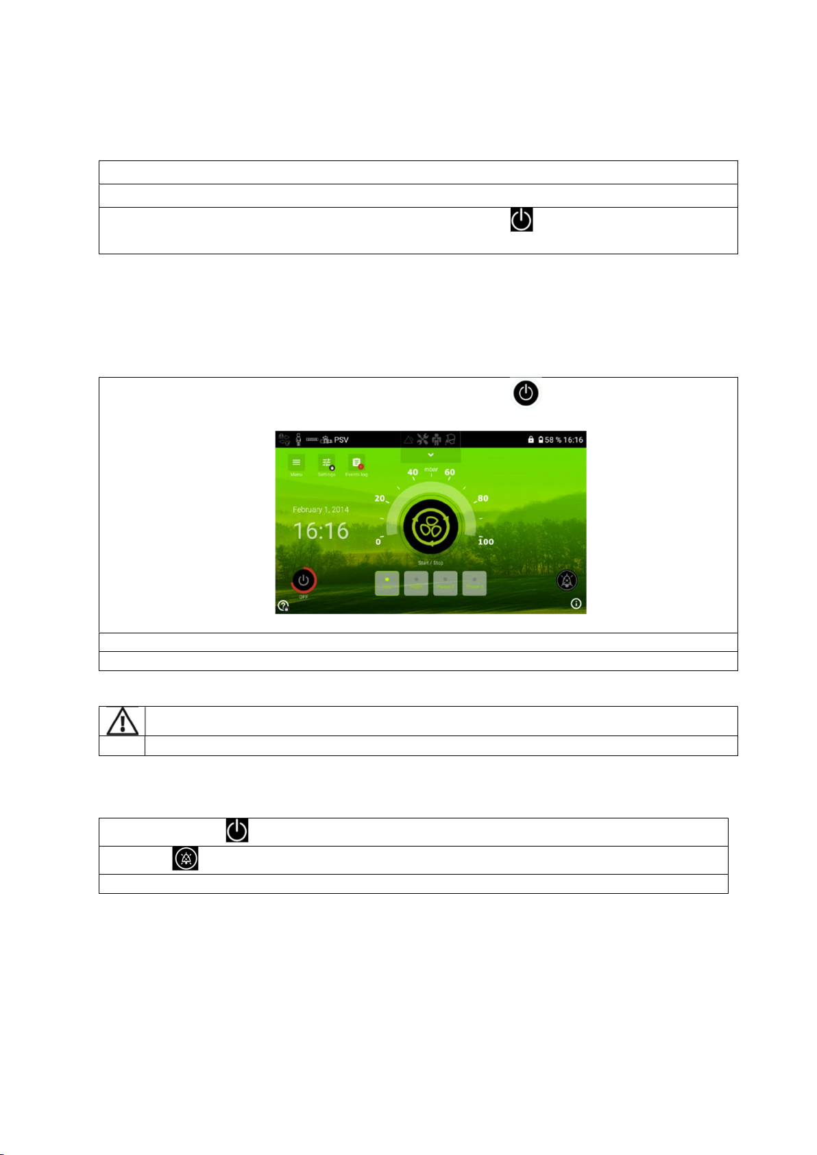
Turning off the device
From the touch interface - Main proceedings
1. From the Home screen of the touch interface, press and hold until the circle becomes red.
2.
A confirmation message is displayed. Validate.
3.
The ventilator turns OFF and the touch interface turns to a deep
-
sleep mode.
WARNING
The EO
-
150 ventilator cannot be powered off during ventilation
From the module - Secondary proceedings
1.
Press and hold
until the ALARM key flashes.
2. Press to confirm.
3.
The ventilator turns OFF.
Starting and Stopping ventilation
Ventilation can be started and stopped from either the touch screen or from the keyboard. Various
preset ventilation treatments may be installed on the device by your clinician to ensure the best
therapy for you. Use these presets according to the instructions provided by the clinician.
To START ventilation using the menu bar:

19
1. Press on the Keyboard
2.
Ventilation starts.
To START ventilation using the Touch Screen:
1. Press on the touch screen
2.
Ventilation starts.
To STOP ventilation using the Keyboard:
1. Press and hold until the alarm key flashes.
2.
Press
to confirm.
3.
Ventilation stops.
To STOP ventilation using the Touch Screen:
1. Press and hold until:
flashes
The red line around the START/STOP key completes a full circle.
2.
The pop
-
up on the screen will ask you to validate your choice. Validate or Press
to confirm.
3. Ventilation stops.
CAUTION
The EO
-
150 ventilator cannot be powered off during ventilation
Unplugging from mains power does not power off the device. It will continue to run on the
internal battery.
The device must be turned off manually before disconnecting from AC power for any
extended period of time. Failure to do so may result in battery depletion and the alarms may
be activated.
Using Stand-by mode
Using Stand-by mode is recommended for an economical use of the battery of EO-150 ventilator,
especially in mobile usage. Stand-by mode will reduce luminosity of the screen. That will preserve
battery and keep system ready to wake up immediately when needed.
By default, the stand-by mode will occur automatically after 2 minutes of inactivity. This feature
could be inactivated in the maintenance menu.
Touching the screen, powering on or inserting the module in the station will wake up the interface
as well. If an alarm triggers, it will wake up the interface immediately.
20
Turning on and off the docking station
If the module is inserted in the docking station, it will power up and power down automatically
following the ventilation module status.
During a storage period or a long period of non-use, the docking station should be switched off.
To switch on and off the docking station and the touch screen, press the docking station Power
button for a few seconds.
The Home Screen
On the home screen, there is important information about the alarms, the pressure of ventilation,
the preset modes set up by your clinician. It also provides menus for choosing your preferences and
calibrating the ventilator. The Home Screen is accessible from all other screens by pressing
Docking
Station
Power B
utton
Other manuals for EO-150
1
Table of contents
Other eove Fan manuals


Popular Fan manuals by other brands


Scarlett
Scarlett Comfort SC-SF111B19 instruction manual

NuAire
NuAire MRXBOXAB-ECO3B installation manual

Hunter
Hunter Spring Mill installation manual

Carrier
Carrier 40VMF Installation and operating instructions

enervent
enervent eWind Pinion Operating and maintenance instructions

Savoy House
Savoy House Nomad 52-EOF-5W-WH owner's manual

Craftmade
Craftmade Mia MI52 manual

Sinclair
Sinclair SF-08C Service manual

STODDART
STODDART Woodson W.MVS Series instruction manual

Mitsubishi Electric
Mitsubishi Electric Lossnay series Technical manual

ARDES
ARDES AR5PR403V Instructions for use

Progress Lighting
Progress Lighting AirPro P250108 installation manual