Epcom KIT-TT4PVTURBO User manual

Quick Setup Guide
Features
Installation and Operation
KIT-TT4PVTURBO KIT-TT8PVTURBO KIT-TT16PVTURBO
Before permanently securing the unit for final installation of cabling
behind walls or ceilings, test for proper operation of the unit and the
cables in your system.
Camera End: Connect transmitter to the camera’s video and
DC power connector. Insert UTP cat5e/6 into RJ 45 jack
of transmitter.
Power
Video
RJ45
DVR End: There’re RJ45 jack labeled “UTP In” and Female BNC
connectors labeled “BNC out” on the receiver hubs.
UTP IN BNC OUT
Insert one end of coaxial patch cord into Female BNC connectors of receiver’
hub and the other end into Female BNC connectors of DVR.
60cm Coaxial cable
Terminate the incoming UTP cat5e/6 cable from transmitter into
your RJ45 jack of 4/8/16 Video & Power Receiver hubs.
DVR
Step 1: Begin with all input/output devices turned off with power cables removed.
Step 2: Connect video source and UTP cat5e/6 cabling to transmitter
Step 3: Connect video display and/or DVR to “BNC output” of Receiver Hub
Step 4: Terminate the incoming UTP cat5e/6 cable into your RJ45
jack “UTP In” (See RJ 45 jack Pin Assignment)
Step 5: Power on all input/output devices
Application Example
Transmitter +Receiver Hub(36VDC)
Power
Video
Power
Video
12VDC Camera
12VDC Camera
Transmitter: convert 36VDC to regulated 12VDC at camera
Power Supply HD Video Receiver Hub
Receiver
Receiver Hub DVR
Transmitter
Switch on the Video & Power Receiver Hub using the on/offf switch.
Multi-Channel 36VDC Power Supply
HD-TVI/CVI/AHD/CVBS 4 in 1 Video Receiver Hub
Provides camera power while receiving video transmission
both over one single 4-pair UTP cat5e/6 cable
No additional power supply needed for cameras
Transmit 36VDC power up to 1000ft /305m working with transmitter
(convert 36VDC into regulated 12VDC) for 12VDC camera
Female BNC connector and RJ45 Jack
Real-time transmission
Exceptional interference rejection
Ground loop isolation
Built-in TVS for surge protection
Lightning protection design Grade: Ⅲ
Wave Filter Design, Anti-Static Design
Compatible with all HD-TVI, HD-CVI, AHD & CVBS analog cameras
Color video max up to 440m(1443ft) for HD-CVI 720P camera
If you adjust saturation of DVR, max up to 470m(1541ft)
Color video max up to 230m(754ft) for HD-CVI 1080P camera
Color video max up to 190m(623ft) for Hikvision TVI 720P camera
Color video max up to 190m(623ft) for Hikvision TVI 1080P camera
Color video max up to 230m(754ft) for TVT HD-TVI 720P camera
Color video max up to 220m(721ft) for TVT HD-TVI 1080P camera
Color video max up to 320m(1049ft) for AHD 720P camera
Color video max up to 320m(1049ft) for AHD 960P camera
Color video max up to 250m(820ft) for AHD 1080P camera
Color video max up to 400m(1312ft) for CVBS camera
Warning !
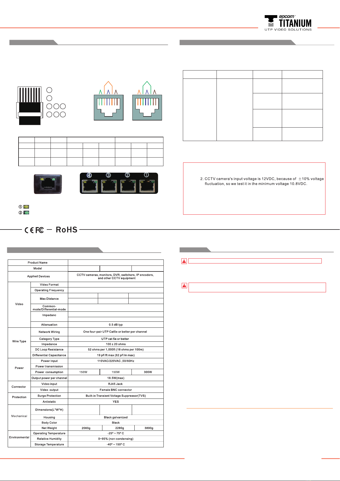
Wiring Scheme
T568A: White
Green Green White
Orange Blue White
Blue Orange White
Brown Brown
White
Orange Orange White
Green Blue White
Blue
White
Brown Brown
Green
T568B:
1 2 3 4 5 6 7 8
Notes: 1.Wire should be category 5e rated Unshielded Twisted-Pair (UTP)
cable.
Video & Power Distance Char t
Video+ Video- Power- Power-
Notes: 1. You can use either T568A or T568B cables,
Make sure that both transmitter and receiver ends use the same wiring.
2. The maximum cable length is 1000ft(305m). For voltage drops over
long distances, refer to the table further in this manual.
Receiver end
Transmitter end
Power Supply HD Video Receiver Hub
Yellow LED ON: Overcurrent
Green LED ON: Power ON
1 2 3 4 5 6 7 8
1
2
3
6
4
7
5
8
Video +
Video -
Power +
Power -
Pair 3 Pair 1 Pair 4
Pair 2
1 2 3 4 5 6 7 8
T568A
Pair 2 Pair 1 Pair 4
Pair 3
1 2 3 4 5 6 7 8
T568B
351*183*44.5mm
(mounting bracket
excluded)
351*183*44.5mm
(mounting bracket
excluded)
557*245*66.5mm
(mounting bracket
excluded)
Important Product Warnings:
1. Always test for proper operation of the unit before permanently securing to final
location.
2. Connect all cables before providing power to the unit.
Safety Instructions
Please be sure to follow these instructions for safe operation of your unit.
1. Read these instructions.
2. Keep these instructions.
3. Heed all warnings.
4. Follow all instructions.
5.Keep this apparatus away from children and unauthorized users.
6.Do not use this apparatus near water.
7.Clean only with dry cloth.
8.Indoor use only. To reduce the risk of electrical shock, keep this apparatus
away from rain, moisture, splashing and dripping liquids. Never put objects filled
with liquid on top of or close to the apparatus.
9.Do not block any ventilation openings.
10.Install in accordance with the manufacturer’s instructions.
11.Do not install near any heat sources such as radiators, heat registers, stoves, or
other apparatus(including amplifiers) that produce heat.
12.Always disconnect mains power when this apparatus not in use or when servicing
or maintenance activities are performed. Handle the power cord by the plug only.
13.Only use attachments/accessories specified by the manufacturer.
14.Refer all servicing to qualified service personnel. Servicing is required when the
apparatus has been damaged in any way, such as power-supply cord or plug is
damaged, liquid has been spilled or objects have fallen into the apparatus, the
apparatus has been exposed to rain or moisture, does not operate normally, or has
been dropped.
Warranty
1.All manufactured products are built to high manufacturing standards and provide
one year warranty.
2.To reduce the risk of electrical shock, DO NOT disassemble or open the cover. No
user serviceable parts inside.Refer servicing to qualified service personnel.
3.All modifications of the apparatus are forbidden for safety reasons. Damage
caused by user modifications to the apparatus is not covered by the warranty.
4.Damaged by disregard of certain guidelines in this manual is not covered by
the warranty.
3. The distance between the camera and the remote video device
must not exceed 1000ft(305m) for color.
4. Actual distance will depend on the camera’s inrush and operating
current, minimum operating voltage, and the wire’s environmental
temperature.
36VDC Power Supply HD Video Receiver Hub
KIT-TT4PVTURBO KIT-TT8PVTURBO KIT-TT16PVTURBO
CVI 720P:400m(1312ft)
CVI 1080P: (721ft) 220m
TVI 720P: 190m (623ft)
TVI 1080P: 190m (623ft)
AHD 720P: 300m (984ft)
AHD 960P: 240m (787ft)
AHD 1080P: 220m (721ft)
DC to 42MHz
15KHz to 42MHz 60 dB typ
36VDC, up to 1000ft /305m via UTP cat5e/6
Mechanical/Technical Specifications
HD-TVI/CVI/AHD/CVBS
UTP:RJ45 100ohms
Coax: Male BNC 75ohms
Power Distance:
Power up to 305m(1000ft) with FS-HD4301VPCT for 12VDC HD camera
Video Distance Chart:
HD transmitter HD receiver Camera type Distance
HD-CVI
HD-TVI
720P 400m(1312ft)
1080P 220m(721ft)
720P 190m(623ft)
1080P 190m(623ft)
720P 300m(984ft)
960P 250m(820ft)
1080P 230m(754ft)
400m(1312ft)
AHD
CVBS
KIT-TT4PVTURBO
KIT-TT8PVTURBO
KIT-TT16PVTURBO
FS-HD4301VPCT
This manual suits for next models
2
Popular Switch manuals by other brands

Marmitek
Marmitek Connect 310 user manual

Advanced Technologies
Advanced Technologies ZRW113 instruction manual

Harman
Harman AMX ENOVA DVX-2250HD-SP quick start guide

FUTABA
FUTABA ESW-2J instruction manual

Cisco
Cisco ASR 900 Series Configuration guide

Allied Telesis
Allied Telesis Switch Controller Quick install guide


