manuals.online logo
Brands
  1. Home
  2. •
  3. Brands
  4. •
  5. FUTABA
  6. •
  7. Switch
  8. •
  9. FUTABA ESW-2J User manual

FUTABA ESW-2J User manual

エンジンカー用電子スイッチ
ESW-2J
取扱説明書
ご使用の前に必ず本書をお読みください。
本書はいつでも活用できるように大切に保管してください。
このたびは電子スイッチ ESW-2J をお買い上げいただきあり
がとうございます。このスイッチは従来の端子接触式ではな
く、FET 回路で電流を制御するので、従来より多くの電流を
流すことができます。また、防塵、防滴構造(IP-64 相当)
ですので粉塵の多いエンジンカーに最適です。
使用上の注意
電源カットモードの選択方法
POWER LED の表示
電源の ON-OFF および接続
ON OFF
バッテリーへ
※乾電池は使用
できません。
受信機へ
電源ボタン
MODE LED
POWER LED
ESW-2J 仕様
寸法
:
23.6×19.6×7.6 mm(コネクター突起物含まず)
定格電圧 
:
4.8 V ~7.6 V(使用可能電圧範囲
:
3.5 V ~8.7 V)
耐電流
:
10 A
(最大 :15 A 30 秒間)
未使用時は必ずスイッチからバッテリーコネクター
を抜くこと。
■このスイッチは OFF 時も微電流が流れるため過
放電してバッテリーが破損、爆発、発火、焼損の
危険性があります。
スイッチは必ず模型に固定した状態で使用する。
■振動や衝撃によりコネクターが抜けると操縦不能
となり、追突の恐れがあります。
充電は必ずスイッチからバッテリーをはずしておこ
なう。
■このスイッチには充電用のコネクターはありませ
ん。スイッチを接続したまま充電すると、爆発、
発火、焼損の危険性があります。
コネクターの極性・ショートに注意する。
■逆接・ショートすると故障や爆発、発火、焼損の
危険性があります。
防振対策をおこなう。
■内部には電子部品が使用されています。振動、 衝
撃、高温等に対する保護対策を施してください。
燃料、排気や水分をかけてはいけない。
■完全防水ではありません。内部には電子部品が使
用されています。燃料や水分が直接かかると故障
します。
配線を強く引っ張らない。
■断線して操縦不能となり、追突の恐れがあります。
分解、修理をしてはいけない。
■このスイッチは構造上分解できません。修理も対
応できません。
ラジコン模型以外には使用しない。   
■このスイッチはホビーラジコンカー用に設計され
ています。その他の用途には一切使用できません。
危険 6.2 V カットモード /5.5 V カットモードを選択した場合、電圧低下すると通電がカットされ、
コントロール不能となります。バッテリー残量、使用時間に十分注意してください。
■走行中にカット機能が働くと、操作不能となり大変危険です。
危険
弊社製品以外との組み合わせにより発生した損害等
につきましては弊社では責任を負いかねます。
①電源ボタンを押したままバッテリーを接続します。
②2 つの LED が点滅したら手を放し、設定モードに入ります。
POWER LED →オレンジ
MODE LED →現在のモード
③電源ボタンを押すたびにモード表示が変わります。
④設定したいモードの LED 表示になったら、電源ボタンを 5 秒
以上長押しします。
⑤2 つの LED が点滅するので手を放します。
⑥設定が書き込まれ、切り替え完了となります。
1. ノーマルモード
緑点灯
POWER LED 2. 6.2 V カットモード 3. 5.5 V カットモード
緑色点灯 7.35 V 以上 6.5 V 以上
赤色点灯 7.1 V~7.34 V 5.8 V~6.4 V
赤色高速点滅 7.1 V 未満 5.8 V 未満
赤色 1 回点滅 6.2 V ( カット ) 5.5 V ( カット )
POWER LED 症状
赤色高速点滅 Low-Battery
赤色 1 回点滅 電源カット
赤色 2 回点滅 ショートもしくは過電流
起動
最低電圧 1. ノーマル 2. 6.2 V
カットモード 3. 5.5 V
カットモード
- 6.6 V 5.6 V
この電圧より低い場合は起動しません。
エラー表示
起動後の電圧表示
電源カットモードを使用する場合
ESW-2J は3つのモードがあります。 6.2 V カットモードまたは 5.5 V カットモードを選択する
と電源切り忘れ時の放電によるバッテリー破損を防ぐ為に電圧が 6.2 V (Li-Po)/5.5 V (Li-Fe) 以下
になると通電がカットされます。バッテリーフェイルセーフ電圧が設定できる場合は必ずカット
電圧より高く設定してください。
双葉電子工業株式会社 デバイス営業センター ホビーラジコン営業部 第一営業課 
〒101-0045 東京都千代田区神田鍛冶町 3-4 oak 神田鍛冶町 8階TEL:03-4316-4819 FAX:03-4316-4823
©FUTABA CORPORATION 2019 年6月 第 1版
■双葉電子工業(株)
ラジコンカスタマーサービス
〒299-4395 千葉県長生郡長生村藪塚 1080
 TEL.(0475)32-4395
このねじ穴を使用してねじ止めするか平滑な
部分へ両面テープで固定してご使用ください。
電源ボタンを長押しで OFF電源ボタンを押すと ON
ボタンを押しながら
バッテリーを接続
モデルへの搭載
1M23N29903
通常は初期設定のノーマルモードでご使用ください。カットモードに
変更する場合は危険性を理解した上でご使用ください。
● Ni-Cd/Ni-MH (4 〜 5 セル )
対応バッテリー:
● Li-Fe (2 セル ) ● Li-Po(Hi) (2 セル )
ノーマル
赤点灯
6.2 V カットモード 5.5 V カットモード
緑点灯 オレンジ点灯
1 2 3
6.2 Vカットモード 5.5 Vカットモード
ノーマル ( カットなし )
6.2 Vまで下がるとカット 5.5 Vまで下がるとカット
初期設定 通常使用モード
● Ni-Cd/Ni-MH
● Li-Fe ● Li-Po(Hi) ● Li-Fe
● Li-Po(Hi)
1 2 3
バッテリーの取り外しは必ず OFF にしてから行ってく
ださい。ON のまま取り外すと次回はバッテリーを接
続しただけで ON になっ
てしまいます。
Electronic Switch Harness
for GP Car
ESW-2J
Precautions
When the model is not being used, always remove
or disconnect the battery.
■When the switch is off, a slight amount of
current still flows. Unless the switch and battery
are disconnected, the battery will be damaged
from excessive discharge.
Always make sure that the switch harness is rmly
attached to the model.
■There is the danger of loss of control and
crashing if the connector is disconnected by
vibration and shock.
Do not charge the receiver battery through the
switch harness. Disconnect the receiver battery
and charge to the manufactures instructions.
■There is no charge connector in this switch.
Never reverse the battery polarity.
■Reverse connection will immediately destroy
the receiver, servo, etc.
Ensure that the unit is mounted in an area that will
eliminate exposure to fuel, water and vibration.
■As with any electronic components, proper
precautions are urged to prolong the life and
increase the performance of the ESW-2J.
Allow a slight amount of slack in the cables and
fasten them at a suitable location to prevent any
damage from vibration during in use.
Never solder the ESW-2J or attempt to repair,
deform, modify or disassemble them.
Do not use the ESW-2J with anything other than an
R/C car model.
1M23N29903
Instruction Manual
Thank you for purchasing the Electronic Switch Harness.
This switch connects a Futaba receiver to a battery and is
turned on and off in an FET circuit. Compared to using a
mechanical switch, it allows more current to be sent with
less loss. In addition, because it is a dustproof and drip-
proof (IP-64) structure, it is ideal for engine cars racing
in dirt/dusty tracks. After reading this manual, store it in a
safe place for future reference.
Connect and power ON-OFF
To receiver
connector
To battery connector
Dry Battery can not be used
Futaba Corp. will not be responsible for damage
caused by combination with other than genuine
Futaba parts.
WARNNG
If 6.2 V cut mode or 5.5 V cut mode is selected, the current will be cut o󱐯 and it will
become uncontrollable if the voltage drops. Be careful with the battery level and
operating time.
■If the cut off function works while driving, it becomes impossible to operate and it
is very dangerous.
DANGER
[ESW-2J Ratings]
• Dimensions: 23.6 mm x 19.6 mm x 7.6 mm (0.93 in. x 0.77 in. x 0.30 in.)
(excluding protrusions)
• Power requirement: 4.8 V ~7.6 V (Voltage range: 3.5 V ~8.7 V)
• Allowable current: ~ 10 A (Maximum allowable current: 15 A 30 s)
POWER
SWITCH
MODE LED
POWER LED
Use this screw hole for screwing, or x it to a
smooth part with double-sided tape.
Install to model
Power cut off mode
POWER LED display
1. Pressing the button rst, next connect the battery.
2. When the two LEDs ash, release the switch to enter the
setting mode.
POWER LED → Orange
MODE LED → Current mode
3. The mode changes each time the Power switch is pressed.
4. When the desired mode LED display appears, press and
hold the Power switch for at least 5 seconds.
5. Release the Power switch when the two LEDs ash.
1. Nomal mode
Green light
POWER LED 2. 6.2 V cut mode 3. 5.5 V cut mode
Green light 7.35 V or more 6.5 V or more
Red light 7.1 V-7.34 V 5.8 V-6.4 V
Red fast ashing Less than 7.1 V Less than 5.8 V
Flash once Red 6.2 V cut o󱐯 5.5 V cut o󱐯
POWER LED State
Red fast ashing Low-Battery
Flash once Red Power cut o󱐯
Flash twice Red Short or over current
Startup lowest
voltage
1.
Normal 2. 6.2 V
cut mode 3. 5.5 V
cut mode
--- 6.6 V 5.6 V
If it is lower than this voltage, it does not start.
Error
Represents voltage
Three modes
ESW-2J has three modes. If you select 6.2 V cut mode or 5.5 V cut mode, the current
will be cut off if the voltage drops below 6.2 V (LiPo)/5.5 V (LiFe) to prevent damage to
the battery due to discharge when the power is turned off.
FUTABA CORPORATION
oak kandakajicho 8F 3-4 Kandakajicho, Chiyoda-ku, Tokyo 101-0045, Japan
TEL: +81-3-4316-4820, FAX: +81-3-4316-4823
©FUTABA CORPORATION 2019, 6 (1)
ON OFF
Long press
Press
Normally, use the default setting Normal mode. When changing to the cut
mode, be sure to understand the danger before using it.
● NiCd/NiMH (4-5 Cells)
Usable battery:
● LiFe (2 Cells) ● LiPo(Hi) (2 Cells)
Keep pressing rst
Next connect the battery
Nomal mode
Red light
5.5 V cut mode
Orange light
1 2 3
6.2 V cut mode
Green light
● NiCd/NiMH
● LiFe ● LiPo(Hi)
6.2 V cut mode
Cut below 6.2 V
5.5 V cut mode
Cut below 5.5 V
● LiFe
Normal mode
No cut
● LiPo(Hi)
1 2 3
Be sure to turn OFF the switch when removing the
battery. Otherwise when reconnect the battery, it
starts up before turning ON.

Other FUTABA Switch manuals

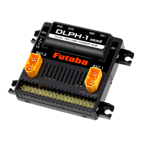
FUTABA DLPH-1 User manual

FUTABA

FUTABA DLPH-1 User manual

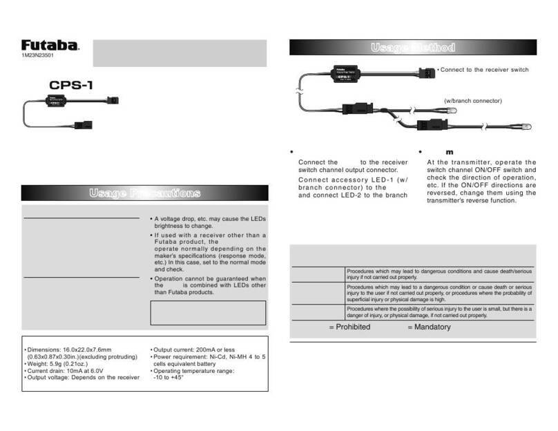
FUTABA CPS-1 User manual

FUTABA

FUTABA CPS-1 User manual

Popular Switch manuals by other brands

Ubiquiti US-16-150W quick start guide

Ubiquiti

Ubiquiti US-16-150W quick start guide

Omron B3SN-3012 manual

Omron

Omron B3SN-3012 manual

AMX VPX-1701 user manual

AMX

AMX VPX-1701 user manual

Juniper EX4200 Series Hardware guide

Juniper

Juniper EX4200 Series Hardware guide

Grundfos MS1 Installation and operating instructions

Grundfos

Grundfos MS1 Installation and operating instructions

Extreme Networks Summit WM100 installation instructions

Extreme Networks

Extreme Networks Summit WM100 installation instructions

Sony MVS-8000X System user guide

Sony

Sony MVS-8000X System user guide

Honeywell miniMAX Quick start configuration guide

Honeywell

Honeywell miniMAX Quick start configuration guide

CAMBRIONIX PowerPad15C user manual

CAMBRIONIX

CAMBRIONIX PowerPad15C user manual

Wi-Tek WI-PMS310GF-UPS user manual

Wi-Tek

Wi-Tek WI-PMS310GF-UPS user manual

Cisco 4900M - Catalyst Switch installation guide

Cisco

Cisco 4900M - Catalyst Switch installation guide

Linkskey LKV-T02 Quick installation guide

Linkskey

Linkskey LKV-T02 Quick installation guide

Vega VEGAWAVE 62 operating instructions

Vega

Vega VEGAWAVE 62 operating instructions

Belden Hirschmann MACH1000 Series user manual

Belden

Belden Hirschmann MACH1000 Series user manual

FCEmaximal MF Series installation manual

FCEmaximal

FCEmaximal MF Series installation manual

ATEN CS72D user manual

ATEN

ATEN CS72D user manual

Intercoax ECP-101T installation guide

Intercoax

Intercoax ECP-101T installation guide

HITROL HTM (HPV)-20N Series instruction manual

HITROL

HITROL HTM (HPV)-20N Series instruction manual

manuals.online logo
manuals.online logoBrands
  • About & Mission
  • Contact us
  • Privacy Policy
  • Terms and Conditions

Copyright 2025 Manuals.Online. All Rights Reserved.