EPE EPS-2000 Series User manual

EPS2000
Table of Contents
Section 1
10 to 40kVA Owner's Manual
Section 2
50
to 125kVA Owner's Manual
Section 3
11 kVA Owner's Manual
Section 4
System Schematics
Section 5
Field Advisories:
Part numbers and Schematics
Section 6
Trouble shooting Guides
Section 7
Distribution Printed Circuit Board Schematics
Notes:
The information contained in this booklet has
proven to be the most useful of what information is
available.
Additional information is available upon
specific requests..

EPS2000
Technical Manual

EPS-2000’” 10 to 40
kVA
Uninterruptible power system
Owner’s manual

IMPORTANT SAFETY INSTRUCTIONS
SAVE
THESE
INSTRUCTIONS-
This
manual
contains
important insf~cfims for
madeis
EPS-2010
(10
kVA),
EPS-2015
(15
kVA).
EPS-2020
(ZOkVA).
EPSZO30
(3WVA)and
EPS-204
(40
WA)
mat
must
be followed during baallatbn,
operation.
and
mabnenance
of
the
UPS
and
a
baReties.
sea
page
4-7
for
Battery
safely
!nstNcffons.
I
m
WARNING
OPENING
ENCLOII_I!?ES
EY?tXES
H.4raRL?o’uS
I
w
VOLTAGES. ALWAYS REFER
SERVlCE
TO QUALIFIED
. PERSONNEL ONLY.
.
f
NOTE
As
standards,
speciticmlon6,
and
designs
shangm
horn
time
to time.
a
pkaseaskfor
conmmation of
the
bdormalii
g’wen
In
thii
puL4iiion.
I
NOTE

EPS-2000” 10 to 40
kVA
Uninterruptible power system
Owner’s manual
1660
Scenic Avenue
Costa Mesa. CA
62626
(714)
557-
1628
Owner’s Manual
l-l
l-2
1-e
1-e
1-e
l-6
1-B
l-7
1-7
1-e
l-8
l-9
l-8
1-9
l-9
1-9
l-12
I-12
l-12
l-12
l-13
l-1.3
l-13
l-13
1-13
I-13
l-13
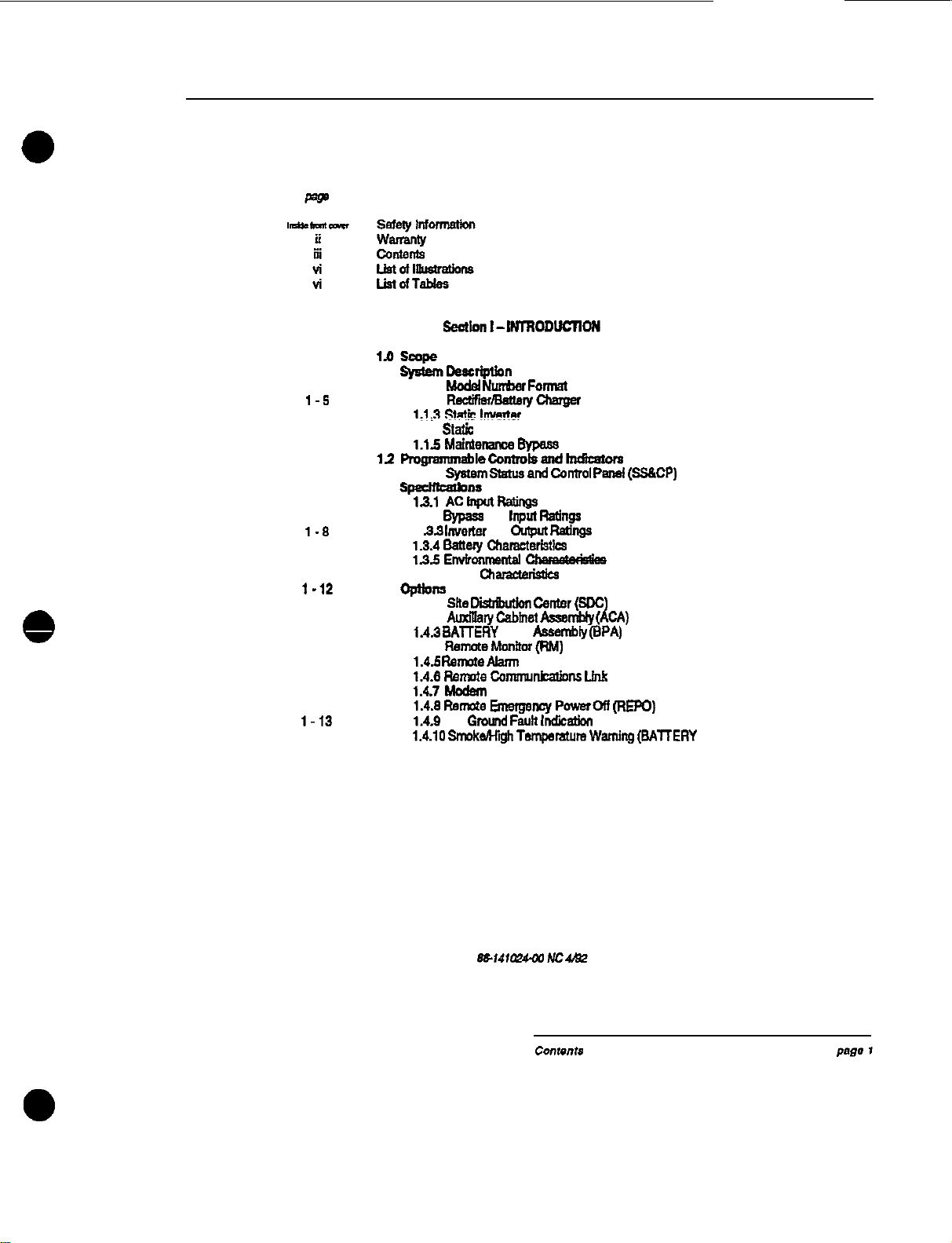
1.1
sy5bm~rlptlan
1.1.1
Mode4
NunWr
Format
1.12
R~efmattmychalQef
,,I*3
tq**
!!!&a!
1.1.4
.Sta!k
Switch
1.15
Malntenanoe
Bypass
11
mQranmmblecontmk.end-
12.1 system
status
and
catml
Pansi
(SaCP)
1.3
SpecmtauDDa
1.3.1
AClnputRstn~s
1.32
Bypass
AC
Input
Rating0
1a.3
IfNetter
AC
Cupan
Ftattlgs
13.4
Eattely
chafacterl3tlcs
1.35
Embnmatal
1.3.6other
chaiaua~
1.4 opuom
1.4.1
SRe
-
center
(sctc)
1.4.2
Adiary
C&M
Aasmb’y
(ACM)
IA.3
BATTERY
PAC
Assembty
@PA)
1.44
Reme
Mdtar
(RM)
1.46
Remote
Akum
Panel
1.4.8
Rmmte
camnkalions
Lhk
1.47
Modem
1.4.8
Ramate
Ems+!Janey
Poweron
(REpo)
1.4.9
DC
Gmlnd
Fault
Irodicti
X4.10
Sn-nkwt@hTsmpsmUm
Warning
(BAllERY PAC)
EPS-2000TY
Uninterruptible Power System
-o-
2-1
2-1
2-I
2-2
2-2
2-a
2-4
2-5
2-5
2-5
Z-10
2-10
2-10
2-10
i-i0
2-11
2-11
2-12
Z-15
2-15
2-15
2-15
2-16
2-17
Z-17
2-19
2-19
2-21
Z-22
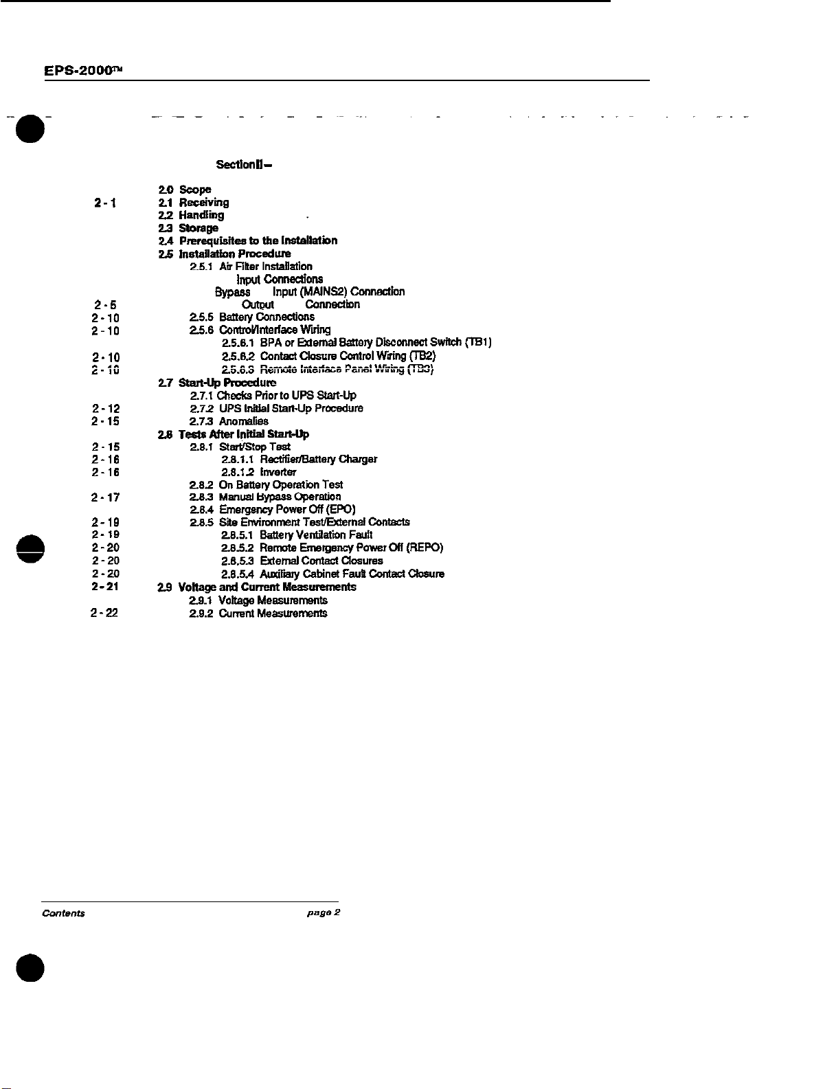
SecUon
II
-
INSTALLATION
2.5.2 AC
input
Cemwdions
25.3
Bypass
AC
Input
(MAlNS2)
Conndon
2.5.4 UPS
o.nwt
Load
CMnedmn
Owner’s Manual
a-i
3-1
3.4
3.4
3-5
3-5
3-e
3-7
3-8
3-e
3-s
3-9
S-10
3-T”
3-13
3-15
3-20
3-22
3-22
3-22
3-n
S-24
3-25
3
-n
3-27
3-n
3-27
.
-.
3-m
3-23
3-23
3-n
3-29
3-30
4-l
4.1
4-2
4-2
4-2
4-3
4-4
4-r
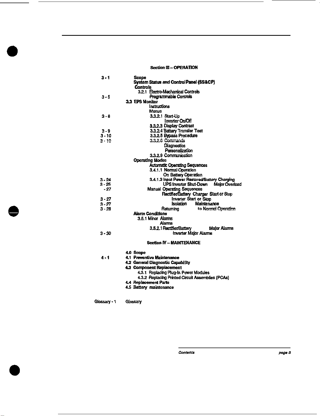
3.0
scope
3.1
Sptem
Status
and
Control
panal
(sS&CP)
32
c0twd9
32.2
P.rqambt3convors
w
EP3tdcmitor
3.3.1
IMona
3.3.2
Menus
3a.21
s(anup
3x2.2
InvetteroI!mf
3323
L&play-
3a24
@atby
Transfer
Test
3a2.5
+
PmceQre
33.26
kT”Tti&
3.3.27
DfagmasUcs
39.23
Person&&n
3829
Comicarion
3.4
Operstlw-
84.1
-op3falhg~~
3.4.1.1
Nomxdoparatbn
3.4.12
01,
Batlety@Wtfm
341.3
lnpl
Pave,
f3cntw~5toy
chmging
3.4.1.4
UPS
lnwrter
Shul-Dovm
or
MnJor
Overbad
3.42
Mmusl
operatins
Sequ-
3.421
RgtaFefmattaly
c!!aget
3t.m 0,
stop
3.422 UPS
I”“erWr
Sfarl
or
stop
3.423 UPS
fsdalion
for
MainfeMnce
3.424
Retumlq
the UPS
to
Norrel
Operakn
3.5
Alamlcondllfons
3.5.1
Minw
Akini-6
3.52 Major
Alarms
352.1
RectifrerlBatlary
charger
t&j07
Namm
3.5.2.2 UPS
fnvaies
Major
bJarnE
EPS-2000” Uninterruptible Power System
1-l
1
I-2
2
1-3
3A
l-4
3B
l-6
4
2-1
5
2-2
6
2-4
6
2-6
9
T-0
10
3-l
11
3-22
12
3-23 I3
3-24
14
3-25
15
3-26
16
3-27
17
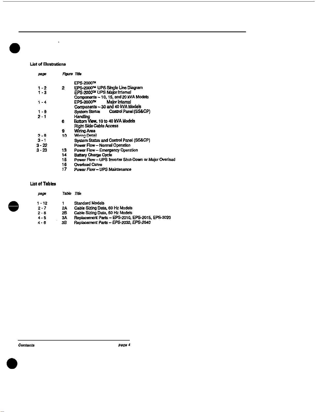
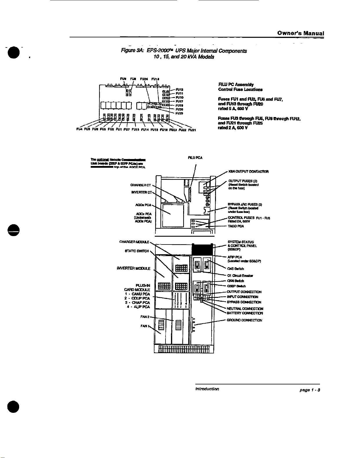
EPS-20Wm Pictorial
EP5-~UPsshlgkLi?aDiawam
El?%zooon
UPS
MaJot
fntemal
~omponents-10,15,and2OkVAModek
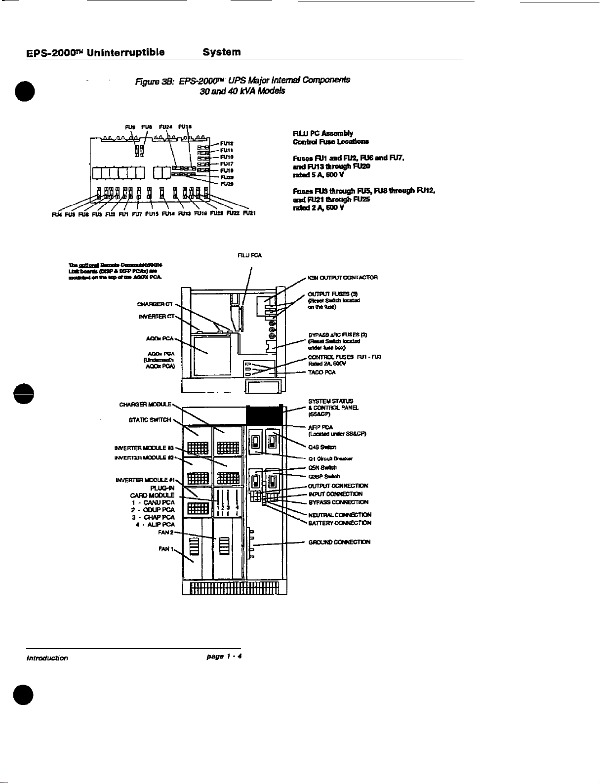
EPS4OOO~
UPS
t&jar
lnlemal
Cornponents-3Oand40k’JAModek
$fmglatua
and
Canlml
Pans1
(SSXP)
BdtomVew.lOio4OkVAM&ls
RigM
Bide
cable
Access
wirim
Area

Owner’s Manual
1.0
scope
This manual
provides
technical information
re-
qulmd
fortheinstallation,operation.and
maim
tenam.
of the
EPS-2CQo’u
Unintenuptfble
Power
SUpply
(UPS) System. Please
read
th’i
manual
thxeugtdy
before
installing
or
operating
the
6PS
2OOW equipment. The manual
is
divided into
four sections:
Sectfon
f
-
Introduction
This
section
melves
as
an
htmductfon
to the
manual and the
EPS-2000TY
series
of UPS
products
rated
10 to 40
kVA.
The UPS &stem
is described, followed by specifications for
standard models, an introduction to
controls
and
fndicators,
and a description
ot
evaitable
optlors.
Section II
-
Installation
This
sectionexpfaiisproceduresforreceiving.
fwndll,
and
staling
the equlpnwnt.
pmmquisires
to the installation procedure. in-
stallatiion,
andeq*pmant start-upprocedures.
sactfonIII
-
0peratton
This
section
descrfbes
the
EPS-2W
System
Status and
Control
Panel
(SS6CP).
includhtg
programmablecontrolsand
indlcators.
eleztrc-
mechanical
controts,
UPSoperating
modes.
and
eystem
slmn
mndllna.
Sectfan
IV
-
Mafntenatwa
This
sectiondescribes
preventffe
maintenance
pmcedures.
diagnostic
capablltles
of the UPS
system. and includes
a
listing
of replacement
parls
for the
vattous
UPS
mod&.
In the
rear
of
the
manual is
a
glossary which
pmvkles
definftiona
for terms
used
within
the
text.
An Index makes it easy to fii
topics
of
interest
Beneath
En&we)
-

EPS-2000’”
Uninterruptible Power System
-0
f
Figure
2:
EPS-ZGOW”
LIPS
S&k
Line
LIiagmm
1.1 System
Descrfplfon
The
EPS-ZOOP
is a”
on-line
static
unintemrp
twe
power supply (UPS) system. designed to
protect
crttkzal
loads from a-lii
nomwdly
encountered
on
a
building’s power
disbibution
system. The
EPSaK!w
UPS and its
auxilii
equipment ca” be
installed
in
a
computer room
or 8”
Bquipmsnt
mom.
Figure
1 is a
pictorial of
the
EPS-2000”’
UPS System
Tha
EPS-2OWN
UPS and its
auxiliary
equip
merit
are listed by Underwriter’s Laboratories,
Inc. (LJL).
Major components of the
EPS-20001Y
include
a
Rectifier/BatteryCharger,
a
transistorized
pulse
width modulated (PWM)
Static
Inverter.
B
co”-
ti”tmusduty rated Static Switch
tich
aulornat~
tally
transfers the load to and from the bypass
AC input source and the UPS
lnverter
output,
an
internal
b4ainterence
Bypass fundion which
is
comprised
of three separate
switches
that
atlows
the critical
bad
to be operated
fmm
the
utility source
while
the UPS
oulput
ts
Isolated
for
service,
and a battery system housed in
8”
exiemat matchingenclosure.
A System Status
&
Control Panel
(SSXP)
pro-
vides
mntmls
to
sslecl
system operation, and
indicators which allow system performance to
be
monitored. A
liquid
crystal display (LCD) is
used to
dispfay
system operating parameters.
provide step-by-step operating
instructiom
to
the system
operator,
and
provide
a
diagraostic
mpablfii
to
assist
in tmubleshwting. The
built-
in EPS Monitor software is
programmed
to dii
play
messages
in
fwe
languages
-
English.
French, German. Spanish, and Italian.
The
EPS-
uses
micmpprcsessors
to
pre
cisely
control operation of the Rectifier/Battery
Charger,
transistorized pulse
width
modulated
(PWM) Static
Inverter,
and
Statii
Switch to
iw
awecptimlsnperfonnwws
for all
line.
kad.
and
operating
conditwns.
In
addition.
a
micmpre
cessor-baseddiignosticsystemassistsintrouble
shooting faulty
assemblies
for replacement, to
minimize service
tinw.
Modular
constmction
thrwghatttheEPS-2000n
UPSfacilitatesmain-
tenance
of the system.
A
singleline
diagram
of the
EPS-2000’”
UPS
system
is
shown
in Fgure 2. The location of the
EPS-2000’” UPS major internal elements is
shown in Figure 3A (10, 15,
&
20
kVA
Models).
Figure
38
(30
&
40
kVA
Models).
-0.
.
R”F.3
I
EPC2000rY
Uninterruptible
Power
SyStSfII
0
0
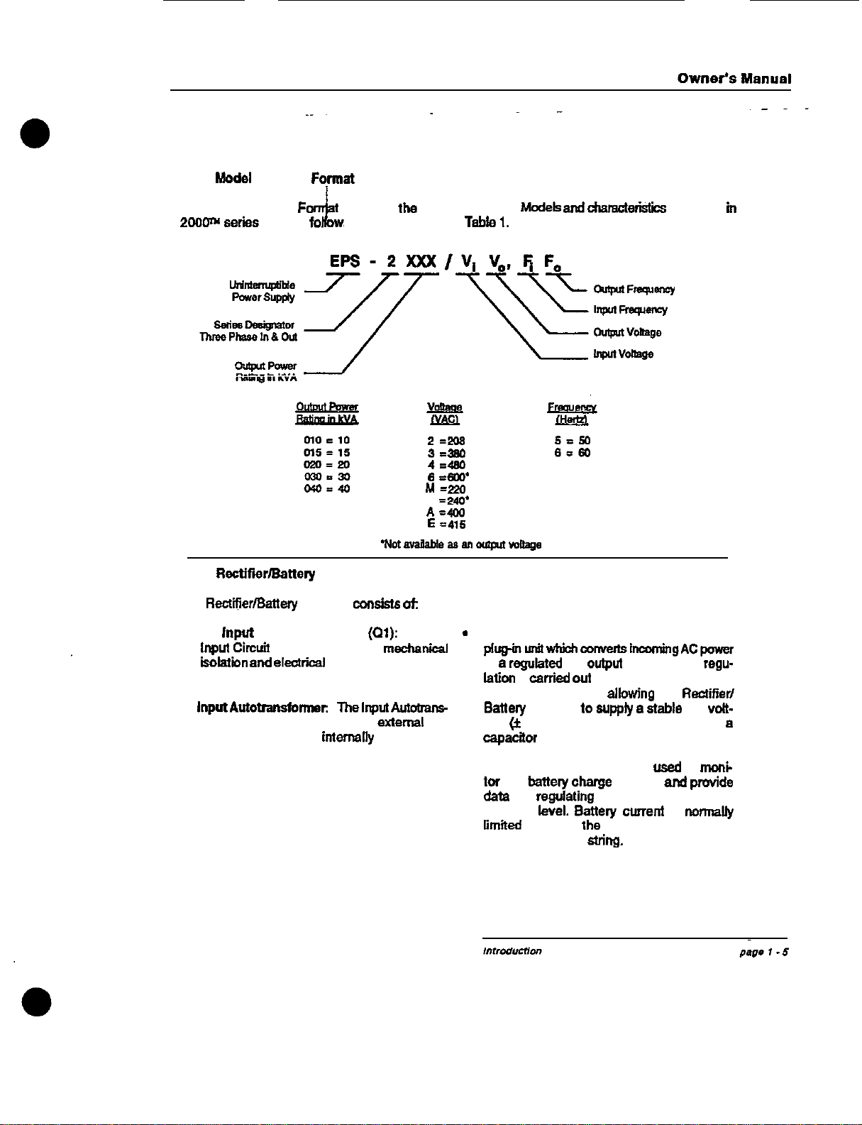
1.1.1
Model
Number
Fqrmat
The Model Number
Fo
used for
the
EPS-
Standard
Models
and
dmmctwkttcs are fisted
fn
2oooN
series
of UPS
fol
s:
Tabkl.
2=208
5=50
3=330
6r60
4=480
e
=ecc*
ht=p.?c
D
=aW
A=403
E
=a6
1.1.2
Rectffk3rBattery
charger
The
Rect?Ldf3attety
Charger
mnskts
of:
l AC
input
Circuit Breaker
@I):
The AC
*
Input
Cinuft
Breaker provides
mecfwkal
koktlln
and
electrical
protection for the in-
put of the UPS.
l
lnputAu!otnnsfomwr
Theltyt-
former k used to match the
external
AC
input source to that
intemaliy
required for
the UPS.
.
Power Module: The Power Module is a
plq-tnti~co-ImgACpaww
to
s
regukted
DC
outpul
voltage. The
regu-
ktion
k
carried
oul
by controlling the SCR
conduction angles.
allowfng
the
Rectffer/
Eattwy
charger
IO
supply
s
stable
DC
vott-
age
(zt
1%). The DC voltage k filtered by
e
capacttor
bank.
DC Shunt: The DC Shunt is
used
to
mot+
tar
the
battery
charge
current
and
provide
data
for
regufating
the DC voltage at the
desired
level.
Battaty
current
k
normalfy
limited
to 10% of lhe Ampere-Hour (Ah) tat-
ing of the battery
sMg.

EPS-20001Y
Uninterruptible Power System
1.1.3
static
lnvertw
The Static lnverter consists of:
c,
Power Module: The Power Module is a
plug-in
mil,
tlsed
to
chop
the DC
vdtage
to
obtain the PWM waveform at the
primary
of
the
output
trarwlomwr.
A single
power
module
is
used
for UPS systems
fwfng
an
outpul
rating
of 20
kVA
or lower. UPS systems
rated above 20
kVA
use three power mod-
ules, one
module
per phase.
lnvetter
Tnmsfortner.
The
b-water
Trens-
former
is
a
fuii
isofeiiin
transformer
which
provides input/output
&ctdcal
isolation
for
the UPS.
provides
the required output volt-
age. and
provides
the required inductance
for
lhe AC output
filter.
AC Output Filter: The output
filter
is used
to achieve
a
computer grade sine wave
output voltage waveform. with
B
Total
Harmonic Distortion (THD) of 4% maximum
(3%
typical).
1.1.4
Statlc
Switch
The
Slalii
Switch transfers the load fmm the
UPSlmrateroutputtofhetypassAC@utsource.
or from the bypass AC input source to the UPS
lnverler Output. without any interruption to the
load
@rovided
that the UPS
Inverter
output is
synchronized to
tie
Bypass AC Input source).
These
transfers
take place
autornatfcaliy
upon
lmerter
start-up
or shutdown. The Static Switch
is rated for
continuous
duty, and is of
plupin
oonstructfon
for ease of maintenance.
The~Rc
circuit
networkproteots
the
St&
Switch
against high voltage spikes and surges by
absorbing the excess energy.
The
ARC
circuft
network
is
protected byIuses.and any failure of
these
f&s
will be displayed- on the
SSBCP
LCD.
1.1.5 Maintenance Bypass
The internal Maintenance Bypass
funotfon
con-
Plsts
of three
swftchee
which.
when
operated
as
spedfied,
provide
a
make-lxefcfe-break
transfer
of the
bad
frun
the UPS
bwerter
output to the
bypassACinputsource.orfromthebypassAC
input
source
to the UPS
lmerter
output. This
feature allows the
crftical
load
to be operated
from the
trtiMy
power source while the UPS
lnverler
output
is Isolated for
mefntenance.
The three internal Maintenance
Bypass
non-auto-
matic switches
are
designated as:
A. Bypass
(MAINSZ)
Input
(04s)
B.
UPS Output Isolation
(Q5N)
c.
Mabllenance
Bypass
(03SP)
Camct
operatfon
of the
thres
switches is
shown
on the Liquid Crystal
Diiay
(LCD). located on
the System Status
&
Contrd Panel (SS&CP) as
part
of the procedure for start-up or shutdown
of the equipment.

Ownar’s
Manual
12 Programmable Controls and Indicators
All
EPS-ZOO(PY
Programmable
Controls
(exch&
lng
chdt
breakersand
nonautomatic
switches)
and
Indicators
we
located on
lhe
Syst~
Siis
and
Control
Panel
(S&Q&P).
12.1 System Status and
cmtml
Pans1
(SSSCP)
The System Status
(L
Control
Panel
(SS&CP)
is
l
lnverter
Status Indicator
l Load on
Bypass
lmlicator
..-...^..e
L.
. .
l
Voltago
kkaa,.,..,...
.aj,ad
l
Cume!!t
kkasummnt
kejpad
l
Maln
Menu Call keypad
l
Entry
Validation or Return To Menu
kevigd
l
Emergency Power Off
(WC)
keypads
shown
In
Figure
4. The
SS6CP
contains the
Detailed
desniptiins
of
the
SS&CP
indiiors
element6 listed below
and the
“se
cd the
SS6CP
keypads are pro-
vided in
Sect&
Ill -OPERATION,
II
3.1.
l
Liquid Crystal Display (LCD)
l
Audible
Alarm
Silence
keypad
l Alarm
lndlcation
l
Scmll Up keypad
l
Scroll Down keypad
l
Ten
Digit
(0 to 9) keypads
l
RectifierIBattery
Charger
Status
Indicator

EPS-200w
Unintenuptible
Power System
l -
0
1.3 Specifications
1.3.1 AC Input Ratings
Refer to
1
1.1
.I
for nominal
V&age
(VAC)
values available.
Voltage:
As specified, nominal
plus (+)
lO%/minus
(-)
15%
Frequency: Nominal. plus
(+)
or
minus (-) 5%
Phases:
wires:
current:
Three, phase rotation A.
6.
C
Three plus
equipment
ground
See Table 2
(page
2
-
7).
Nominal AC
Input
Current
Power Factor: 0.82 lagging minimum al full
bad output, nominal input voltage. and
nornal
float
voltage an battery
1.32 Bypass AC
Input
Ratings
voltage:
Must
match UPS
nonkal
output
voltage
*
10%
Frequency Window Nominal plus
(+)
or
minus
(-) 0.25, 0.5,
0.73,
or 1.0 Hz. Standard
seihg
for bypass input frequency
wkbw
is
*
0.5
Hz
ullb?&%
olhelwis9
qJacified
when
M-
dered. The Frequency
Window
can
be changed
after the
unii
is installed,
but
requires
a
visit by
an EPE authorized Customer
Support
Services
(CSS)
represe”taive
to
modii
the equipment
Contact
EPEs
Customer Support Services or-
ganizationforfurtherinformation.
Phase:
Three, phase
rotation
A,
6.
C
wires:
Four
wire
WYE
CUfP3llt
See Table 2 (page 2
-
7),
UPS
output
ad
Bypass
AC
Input
Current at
speck
fied
nomiMI
output
voltage.
Power Factor. bad dependent
1.3.3
lnverter
AC Output Ratings
Refer to
1
1.1
.I
for nominal
V&age
(VAC)
valuesavailable.
voltage:
Nominal value
*
1% for all
conditions of line. load, and temperature
Frequencyz
Nwmally
q’“chrunhed
lo
the by-
pass AC
inplt
source
(when available): other-
wise the output frequency is the nominal value
+
0.1%.
Phase:
Three. phase
rdatbn
A,
8.
C
Wires:
Three or
four.
The UPS
hlverter
output is
a
WYE
cor@uratbn
with the neutral
grounded. A three wire DELTA
load
can
be
o~nneckd
to the UPS
lnverter
output, but the
phase
ccmnecliorw
cannot
he
grounded.
Curmnt
See Table 2
@age
2
-
7),
UPS
Output
and
Bypass
AC
Input
Current at
speck
fled nominal input voltage.
Power Factor: The UPS
bwerteroutpul
is
rated
al
full
MIA.
0.8
power
factor lagging bad.
Slew Rate:
The rate
cd
change of the UPS
1~~r(~~r~h~~.(~)tiam2.de~
dhin
the
frequenay
window (see
Eiypass
AC
Input
Ratings
-
Frequency Window).
@)
when
sy”-
chronhing
lo
the bypass AC
inpul
source. or
(c)
when going to
a
free
nm”ing
oonditb”
after
losing AC input power, is 1
Hz&c
maximum.

Owner’s Manual
Overload
Characterfstlcs:
Appfles
to the UPS
Output when operating
from
ekher
the
bypass
AC input
sc”me
or
the UPS
lmerter
output:
125% for 10 minutes
150% for 1 minute
Overloads in
excess
of 150%
or
exceeding the
overload
time
periods
previcnsly
indicatedwill
cause
the Iced to be
tmnsfened
from
the
UPS
lnverler
output to the
bypeec
AC input
scume.
prcvfded
the sources are
synchmnized.
Once
the
load
is transferred to the
bypass
AC input
soiime
ski
cxaeediiing
the time
periods
preti-
ously
indiied.
the timed
periods
will
stall
again
for
cpemttcn
cn
the UPS Static
Switch. If the
load does not return to less then the
tmb’s
full
Iced
rating
prior to
ccmpleting
the timedwer-
load
park&.
the
ked
wffl
be
disccnnected.
Dynamic
Charactetfetics:
Peek
voltage
devia-
ticn
on the UPS
lnverter
output
is
listed
belaw
for
the
mndiikms
imliied:
50% step
load
change
+3%maximum
100% stepbad
change
*
5%
maximum
Bynamlc
Response: The UPS
lnvetter
output
voltage
retmns
to
f
1%
of
ncmhml
wfthin
one
cydeafterexpetiencfng
a
108%steplced
change
1.3.4 Battery
Characterlstfcs
DC Voltage Range:
325 Vdc minimum
438 Vdc maximum
-
1.3.5
Envfronmental
Character-ktics
Temperature:
oparatlng
Range:
w
c. to
+4(P
c.
(Excluding battery)
Noa-Cperating
and
Storage:
-25’ c. to
+7w
c.
Rettotrtmettded
Environment:Computer
Room
or
ether
temperature
mntrclled
envimnmect
Recommended Temperature: 20 to
300
C.
(Battety
prctecticn
time is based
on
e
29C.
ambient
temperetwe)
Rscommended
Relative Humidity: 50%
1.3.6
Other
Chamoterlstke
Audible
Noise
Level:
10 to 40
kVA
ratings:
5
88
dBA
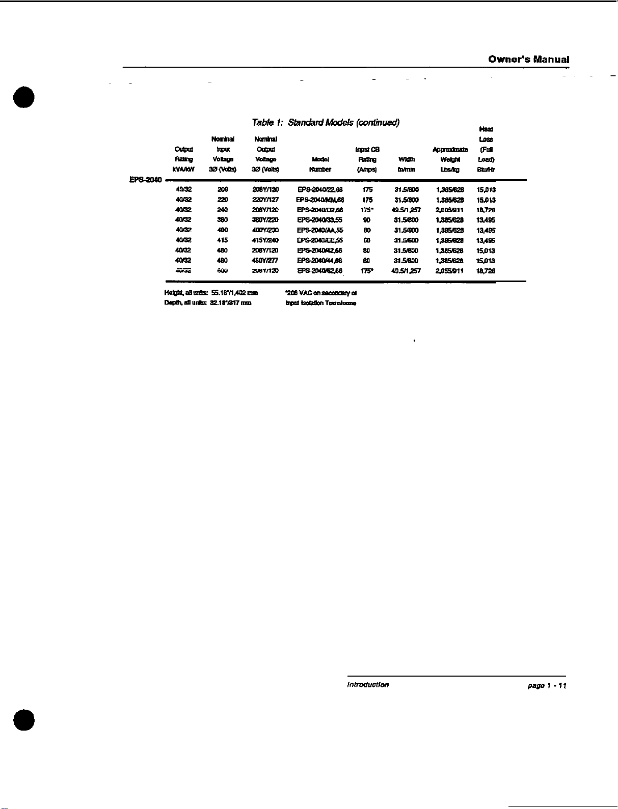
PhyekalDimensions:
Height
56.18’/1.462
mm
Depth:
32.16*/817
mm
Width:
See Table 1
DC
Currant
Requlr&
Weighk
SeeTable
See
Table
2 (page 2
-
7).
Mmdmum
Battery Current.

EPS-200w
Uninterruptible Power System
,/mcd”C”on
page
I
-
IO
0
0
Other manuals for EPS-2000 Series
2
This manual suits for next models
5
Table of contents
Other EPE UPS manuals


Popular UPS manuals by other brands


Ametek
Ametek SURGEX Security Plus II UPS-42100-85R user manual

Emerson
Emerson itON BX quick start guide

ABB
ABB PowerValue 11 T Series user manual

Digital Equipment
Digital Equipment HA3000 installation manual

Riello
Riello SENTINEL RACK SER 1500 Installation and use manual

GE
GE Digital Energy SG Series installation guide


