EPE EPS-2000 Series User manual

EPS-2000’” 50 to 125
kVA
Uninterruptible power system
Owner’s manual

IMPORTANT SAFETY INSTRUCTIONS
SAVE THESE INSTRUCTIONS
-
This manual contains important instructions for models
EPS-2051 (50
kVA),
EPS-2061 (60
kVA).
EPS-2081 (80
kVA),
EPS-2101 (100
kVA)
and
EPS-
2121 (125
kVA)
that must be followed during installation. operation, and maintenance of the UPS
and its batteries. See page 4-5 for Battery Safety Instructions.
I
f
WARNING
OPENING ENCLOSURES EXPOSES HAZARDOUS
VOLTAGES. ALWAYS REFER SERVICE TO QUALIFIED
PERSONNEL ONLY.
I
t
NOTE
As standards, specifications. and designs change from time to time,
*
please
askfor
confirmation of the information given In this publication.
I
NOTE
This equipment generates and uses radio frequency energy, and if not
installed end used in strict accordance with the manufacturer’s instruc-
tions, may
csuse
interference to radio and television reception.
lt
has
been type tested and found to comply with the
limit6
for
e
Class A
e
computing device in accordance with the specifications in Part 15 of
FCC Rules, whicharedesignedtoprovidersasonableprotectionsgsinst
such interference in
e
residential installation. However. there is no
guarantee that interference will not occur in
e
particular installation.
+
v
prepared for:
EPS-2000-
50
to
125
kVA
Uninterruptible power system
Owner’s manual
for service
calf:
1
-
600
-
GETS
-
EPE
66-141025-00
NC
4162
Copyright
0
1991 EPE Technologies. Inc.
All rights resewed. Printed in U.S.A.
1660 Scenic Avenue
Costa
Mesa.
CA 92626
(714) 557
-
1636
EPS-2000’” 50 to 125
kVA
Uninterruptible power system
Owner’s manual
Owner’s Manual
Contents
Safety information
ii
Service and factory repair
ii
Warranty
iii
contents
”List of illustrations
vi
How to use this manual
Section I
-
l-l
l-2
1-4
l-7
l-7
l-7
1-7
l-7
l-8
l-8
1-9
l-9
1-9
1-9
l-10
l-11
l-11
l-11
introduction
1.0
1.1
1.2
1.3
1.4
scope
General Description
1
.l
.l
Model numbering
1.1.2 Input autotransformer
1.1.3 Rectifier/battery charger
1.1.4
Static inverter
1
.1.5
Static switch
1.1.6
Output transformer
Programmable controls and indicatora
1.2.1 System status and control panel
(SS&CP)
1.2.2 Circuit breaker
Specificationa
1.3.1
AC input ratings
1.3.2 AC output ratings
1.3.3
Battery characteristics
1.3.4
Mechanical characteristics
1.3.5
Environmental characteristics
Options
Section II
-
Installation
2-1 2.0 scope
2-1 2.1 Receiving
2-1 2.2 Handling
2-2 2.3 Storage
2-2 2.4 Prerequisites to the installation
2-2
2.4.1 Environmental
2-2 2.4.2 Mechanical
2-3 2.4.3 Electrical
2-4 2.5 Installation procedure
2-5
2.5.1 UPS output load connections
2-7 2.5.2 AC input connections
2-7 2.5.3
Control and interface wiring
2-8 2.5.4
Banely
connections
2-9 2.5.5 BPA-2000 or
bansry
disconnect switch
86-747025-00
NC
4/92

EPS-2000’~
Uninterruptible Power System
0
Pa- dW&“O”
2-9 2.6
Start-up
procedure
2-9
2.6.1 .Checks prior to start-up
2-10 2.6.2
Initial start-up
2-10 2.6.3
Checks after start-up
section
III
-Operation
3-1
3-1
3-1
3-2
3-6
3-7
3-7
3-7
3-7
3-6
3-11
3-72
3-15
3-16
3-16
3-16
0
3-21
3-25
3-26
3-37
3-39
3-39
3-40
3-40
3-41
3-42
3.0 scope
3.1
System
etatus
and control panel (SS&CP)
3.1
.l
Liquid-crystal display (LCD)
3.1.2 Keys
3.1.3
Indicators
3.2
Controls
3.2.1
Electra-mechanical
controls
3.2.2 Programmable controls
3.3
EPS monitor software
3.3.1 Initial start-up condition
3.3.2 Menus
3.3.2.1 Start-up
3.3.2.2
lnvsfter
on/off
3.3.2.3 Display contrast
3.3.2.4 Battery transfer test
3.3.2.5 Bypass procedure
3.3.2.6 Commands
3.3.2.7 Diagnosis
3.3.2.6
Personalization
3.3.2.9 Communication
3.4
Alarm condltiono
3.4.1 Minor alarms
3.4.2 Major alarms
3.4.2.1 Rectifier/battery charger major alarms
3.4.2.2 lnvetter major alarms
3.5
UPS isolation
Section IV
-
Maintenance
4-1
4.0
scope
4-1 4.1
Preventive maintenance
4-2 4.2
General diagnostic capability
4-2 4.3
Component replacement
4-2
4.3.1 Plug-in modules
4-3 4.3.2
Replacing printed circuit assemblies
(PCAs)
4-4 4.4
Replacement parts
4-6 4.5
Battery maintenance
Conlenfr page
I”
Owner’s Manual
Appendices:
Appendix A-Optima
A-l
A.0
A-l A.1
A-2 A.2
A-2 A.3
A-3 A.4
A-4 A.5
SCOP9
Power warning interface (IBM
AS/400)
Remote communications link
Remote alarm status panel (RASP)
Remote monitor/control panel
DC ground fault detector
Appendix B-Typical configurations (100 and 125
kVA)
B-1
8.0
B-1
8.1
B-2
8.2
B-2 8.3
B-3 8.4
B-4 8.5
B-4
B.6
B-5 8.7
B-6 8.8
SCClpe
Baseline system
EPS-2000 UPS with maintenance bypass
EPS-2000 UPS with 208,220, or 415 VAC output
EPS-2000 UPS with 208 or 600 VAC input
EPS-2000 UPS with input isolation and maintenance bypass
EPS-2000 UPS with output isolation and maintenance bypass
EPS-2000 UPS with output panelboards
EPS-2000 UPS with 208 VAC input and output
Glossary-1 Glossary
Index-l
Index
Illustrations
l-l
1
l-4 2
l-5 3A
1-6 30
1-8 4
2-1 5
2-3 6
2-3 7
2-4
8
2-5
9
2-a
10
3-1 11
3-9
12
4-l
13
4-3 14
EPS-2000 125
kVA
pictorial
EPS-2000 UPS single-line diagram
Location of major internal components
location of major internal components Model 2101 and 2121
System status and control panel
(SS&CP)
Handling
Bottom view showing iloor tile cut-out dimensions
Right side cable access
Leveling jacks
Wiring area
Connection detail. terminal block TB-1
System status and control panel
(SS&CP)
LCD graphic symbols
Air flow
Location of card module

EPS-2000rU
Uninterruptible Power System
How To Use This Manual:
This manual is designed for ease of use and easy location of information
on an as-needed basis.
The manual is divided into four sections as described in the Introduction.
To quickly find the meaning of terms used within the text. look to
the Glossary.
To quickly find references for major topics (such as subassemblies) or to
terms shown on the equipment. look to the Index.
The paragraph symbol (ll) indicates numbered paragraphs that can be
quickly found in the Contents on page iii.
This manual uses Noteboxes to convey important information. Noteboxes
come in four varieties:
I
WARNING
t
A WARNING
notebox
indicates
information provided to protect the
l
user and service personnel against
I
safety
hazards and/or possible equip-
ment damage.
I
IMPORTANT
11
An IMPORTANT
notebox
indicates
information provided as an operat-
ing instruction, or as an operating
l
tiD.
I
CAUTION
t
A CAUTION
notebox
Indicates
w
’information provided to protect the
m
user and service personnel against
I
possible equipment damage.
NOTE
A NOTE
notebox
indicates informa-
tion provided as an operating tip or
l
an equipment feature.
Owner’s Manual
Introduction
I
.o
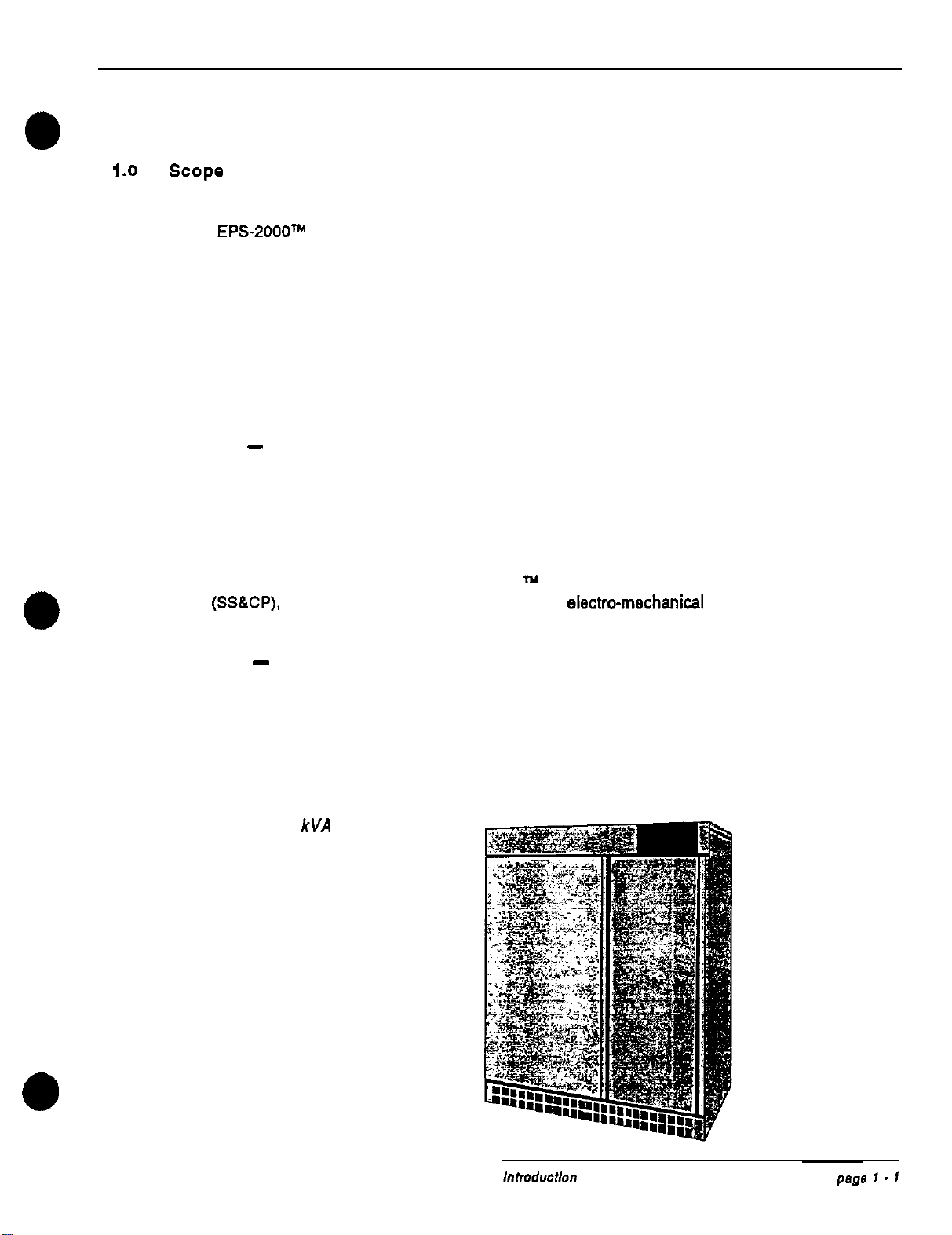
Scope
This manual provides technical information required for installation, operation, and maintenance
of the EPS-2000TM Uninterruptible Power System (UPS). Please read this manual thoroughly
before installing or operating the EPS-2000 equipment.
The manual is divided into four sections:
Section I -Introduction
This section serves as an introduction to the manual and the EPS-2000 family of UPS products.
The UPS is described; followed by specifications for standard models: and an introduction to
controls and indicators.
Section II
-
Installation
This section explains procedures for receiving. handling, and storing the equipment: prerequisites
to the installation procedure; installation: and equipment start-up procedures.
Section Ill -Operation
This section describes operation of the
EPS-2000
1y
UPS, including the system status and control
panel
(SSKP).
programmable controls and indicators, electro-mechanical controls, operating
modes. alarm conditions, and isolation of the UPS.
Section IV
-
Maintenance
This section describes preventive maintenance procedures; EPS-2000 diagnostic capabilities;
remedial maintenance routines; and a listing of replacement parts.
In the rear of the manual is a Glossary that provides definitions for terms used within the text.
An Index makes it easy to locate topics of interest.
Figure 1: EPS-2000 125
kVA
pictorial

EPS-2000TY
Uninterruptible Power System
1.1
General description
The EPS-2000 is an on-line static uninterruptible power system (UPS) designed to protect critical
loads from anomalies commonly encountered from power utilities. The EPS-2000 UPS and its
auxiliary equipment can be installed in a computer room or an equipment room. Figure 1 is a
pictorial of the EPS-2000 UPS.
The EPS-2000 UPS and its auxiliary equipment are Listed for Safety by Underwriter’s Laborato-
ries. Inc. (UL) under UL Standard 1778
-
Uninterruptible Power Systems.
Major components of the EPS-2000 include:
.
Rectifier/battery charger
-
rectifies ac input to dc for maintaining battery charge
.
Input autotransformer (optional)
-
matches input source voltage to that required
internally by the UPS
.
Transistorized pulse-width-modulated (PWM) static inverter
-
converts dc from
the rectifierlbanery charger (or from the battery when in battery operation mode)
to ac output voltage to maintain attached critical loads
.
Output transformer (optional)
-
provides the required output voltage for
attached loads
.
Continuous-duty rated static switch
-
automatically transfers between bypass
ac
source and
inverler
ac
output
.
External battery system
-
stores energy for utilization by the inverter (and attached
loads) in the event that utility ac input power is lost or of unacceptable quality
A system status and control panel
(SSSCP)
provides controls to select system operation. and
indicators that allow system performance to be monitored. A liquid-crystal display (LCD) is used
to display system operating parameters; provide step-by-step operating instructions to the system
operator; and provide a diagnostic capability with instructions to assist in troubleshooting.
The built-in EPS monitor software is programmed to display its messages in any of five (5)
languages
-
English, French, German, Spanish, and Italian.
The EPS-2000 uses microprocessors to precisely regulate operation of the rectifier/battery
charger. transistorized pulse-width-modulated inverter, and static switch, to assure optimum
performance for all line. load. and operating conditions. In addition. a microprocessor-based
diagnostic system helps troubleshoot faulty assemblies within the EPS-2000 UPS, to minimize
time required to restore system operation in the unlikely event of an internal UPS fault. Modular
construction throughout the EPS-2000 UPS facilitates maintenance of the system.
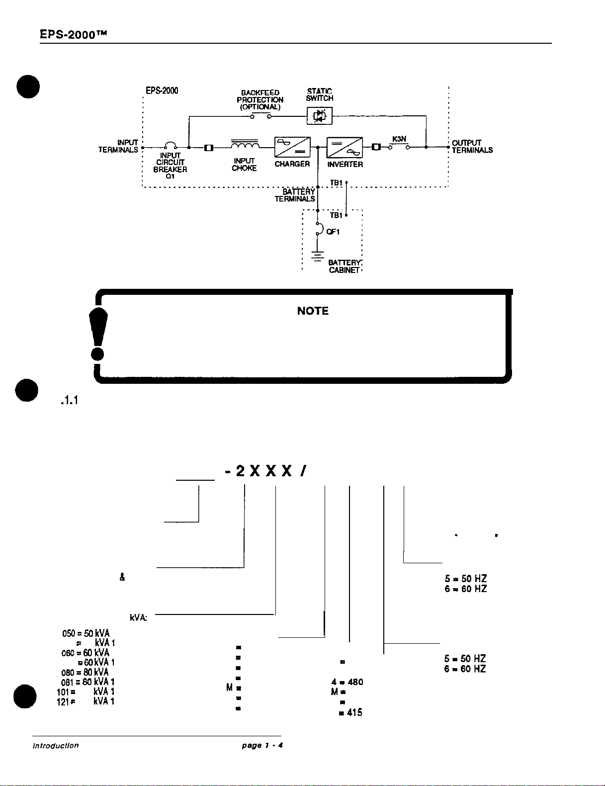
A single-line diagram of the EPS-2000 UPS is shown in Figure 2. The location of major internal
components within the EPS-2000 UPS is shown in Figure 3.
The EPS-2000 100 and 125
kVA
UPS are 480 VAC input, 480 VAC output devices. The
EPS-
2000 50-80
kVA
UPS are offer in 2081208, 2201220 or
4801480.
When different input
and/or
l
output voltages are specified, external transformers provide the step-up and/or
step-down
func-
tions as required. These transformers
are housed
in auxiliary cabinets, either an ACA-2000 or
SDC-2000 or both.
In addition to housing voltage matching transformers, each of these auxiliary
cabinets can house optional equipment as well.
Owner’s Manual
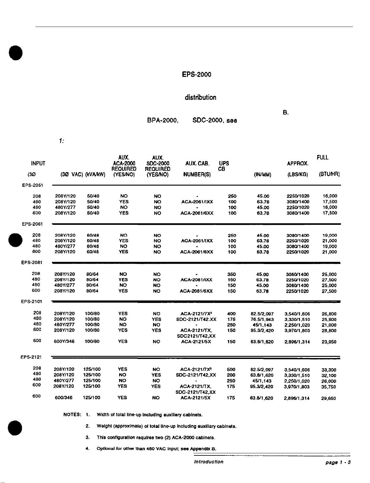
Table 1 details the different auxiliary cabinets used for all possible input/output voltage combina-
tions. For example, if your configuration requires 208 VAC input and output, your
system
will
consist of an EPS-2000 UPS and two ACA-2000 cabinets. as shown in the table.
The EPS-2000 UPS is part of the modular
EPS-2000
family which includes the EPA-2000 battery
system, the ACA-2000 auxiliary cabinet. and the SDC-2000 site distribution cabinet. and options
available for each of the modules. The EPS-2000 family provides unlimited flexibility in designing
and field-upgrading a power protection and distrfbution system to meet the requirements of any
facility. Your configuration may vary somewhat from the bass-line EPS-2000 UPS system de-
scribed in this manual. For examples of typical configurations, see Appendix
8.
For further
information on the ACA-2000.
BPA-2000,
and
SDC-2000.
see the owner’s manual for each
particular
module.
Table
7:
Typical EPS-2000 system configurations by input and output voltage
A”X. A”% TOTAL
FULL
LOAD
INPUT
OUTPUT OUTPUT
ACA-2000
SDC-*ow
AUX.
CAB.
UPS
INPUT TOTAL
APPROX.
HEAT
VOLTAGE VOLTAGE RATING
REOUIRED REOUIRED
MODEL
CB
RATING’ WIDTH’ WEIGHT’
LOSS
(30
“AC)
(30
“AC)
(WA/NV) (YESNO) (YESNO) NUMBER(S)
(AMPERES,
(IWMM) (LSSXG) (BTUMR)
EPS-~OOO’~
Uninterruptible Power System
Figure 2: EPS-2000 UPS single-line diagram
:
EPs2oGa
Refer to Appendix B for further information on the auxiliary cabinet
f
supplied with the EPS-2000 UPS when the specified input andforoutput
voltage is other than 208,220 or 480 VAC.
1
.I
.l
Model numbering
The model numbering system used for the EPS-2000 UPS is shown below: standard configura-
tions and their respective auxiliary cabinet requirements are identified in Table 1.
EPS
-2XxX
/
X X , X X X
---- ---
UNINTERRUPTIBLE
POWER SUPPLY
SERIES DESIGNATOR:
THREE PHASE
IN
h
OUT
OUTPUT POWER
RATING IN
kVA:
050
E
50 kVA 0
SERIES
051
a
50
kVA
1
SERIES
060
3
50 kVA 0
SERIES
061
=
M) kVA
1
SERIES
080
=
80 kVA 0
SERIES
oB1
=
80 kVA
1
SERIES
101
=
100
kVA
1
SERIES
121
c
125
kVA
I
SERIES
INPUT VOLTAGE (VAC):
2
-
208
3
-
380
4
-
480
6
-
600
M
=220
D
-
240
A
I
400
E-415
OUTPUT VOLTAGE
2
-
208
3 -380
4-480
M
*
220
A
-
400
E
-415
L
INTERNAL USE
ONLY:
A
-
Z OR 0
-
9 DIGIT
1OUTPUT
FREQUENCY:
5-50HZ
6=60HZ
INPUT
(VAC): FREQUENCY:
5-50HZ
6-60HZ
Owner’s Manual
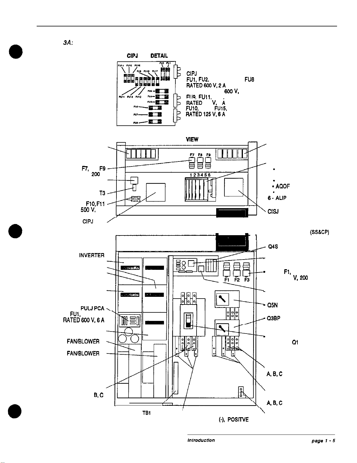
Figure
3A:
Location ofmajor internal components on model EPS-2000 (SO-90 KVA)
CIPJ
PCA
DETAJL
CIPJ FUSES:
FUl.
FlJ.2.
FU5 THROUGH FU6
RATED6%JV,ZA
FU3. FU4 RATED 600 V. 6 A
FU9.
Full.
FU13. FU14. FU16
RAYED 256
V,
2
i
FUlO, FU12. FU15. FU17
RATED125V.6A
DC CAPACITORS TOP VlEW AC CAPACITORS
FUSES
n,
F6, F9
RATED 600 V,
2W
A
T4
T3
FUSE
FlO,
Fll
RATED 500 V, 2 A
CARD CAGE:
1
-
CANF PCA
2 -CHAP PCA
3
-
ODUP PCA
4
_
AQOF PCA
5
-
AOCF PCA
6.
ALIP PCA
CISJ PCA
CIPJ PCA
/
FRONT VIEW
INVERTER
LEG 1
LEG 2
LEG 3
STATIC SWITCH
F
FUSES
FM,
FU2, FU4
RATED6LXV.6A
CHARGER
FANBLOWER 1
FAMELOWER
2
INPUT CONNECTIONS:
A.
B,
C
1
TERMINAL BLOCK TBl
SYSTEM STATUS AND
CONTROL PANEL (SS6CP)
1
‘BATTERY CONNECTIONS:
-
GNUF PCA
-
FUSES
Fl,
F2. F3
RATED 600 V. 200 A
-
K4
-
Q5N
_
Q3BP
-
MAIN INPUT CIRCUIT
BREAKER
Ql
’
BYPASS CONNECTIONS
A.&C
OUTPUT
CONNECTIONS
A.B,C
GROUND
REMOTE COMMUNICATION NEUTRAL, NEGATIVE (-). POSITVE (+) CONNECTION
AND POWER WARNING INTERFACE
EPS-2000TM
Uninterruptible Power System
0
Figure
38:
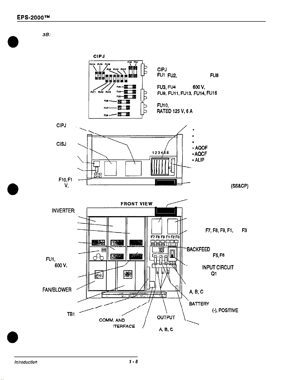
Location of major internal components on model 2101 and2121
CIPJ
PCA DETAIL
CIPJ
FUSES:
FUl
,
FUZ.
FU5 THROUGH
FUB
RATED 600 V. 2 A
FU3.
FW
RATED
600
V.
6 A
FUQ,
Full.
FU13,
FU14,
FlJ16
RATED 250 V. 2 A
FUlO,
FU12, FU15. FU17
RATED125V,6A
CIPJ
PCA
(SEE DETAIL ABOVE) TOP VIEW CARD CAGE:
1
-
CANF PCA
2
-
CHAP PCA
CISJ
PCA
T4
T3
FUSE
Fl
0.
Fl
1
RATED 600
V.
2 A
fl
I
3
-
ODUP PCA
4
-
ACOF
PCA
5
-
AClCF
PCA
6
-
ALIP
PCA
MIND PCA
(OPTIONAL)
SYSTEM STATUS AND
CONTROL PANEL
(SSSCP)
INVERTER:
LEG 1
LEG 2
LEG 3
BTRJ PCA (OPTIONAL)
FUSE RATED 500 V, 2 A
GNUF PCA
FUSES
F7,
F6.
FQ,
Fl.
F2,
F3
RATED 600 V. 250 A
STATIC SWITCH
PUW PCA
FUSES
FUI,
FU2. FU3
RATED
600
V.
6 A
SACKFEED
PROTECTION (OPTIONAL)
FUSES F4,
F5.
F6
RATED 600 V, 2 A
MAIN
INPUTCIRCUlT
BREAKER
01
CHARGER
INPUT CONNECTIONS:
FANBLOWER
1
A.
8-C
FAN/BLOWER 2
BATTERY
CONNECTIONS:
TERMINAL BLOCK
TSl
NEGATIVE
(-),
POSlTlVE
(+)
REMOTE
COMM.
POWER WARNING
IN CONNECTIONS: GROUND
CONNECTIONS
CONNECTION
NEUTRAL
(OPTIONAL) CONNECTION
,“,mducNO”
page
1
.6

Owner’s Manual
1
.I
.2
input autotransformer (optional)
The input autotransformer is used to match the external ac source voltage to that required inter-
nally by the UPS. The input autotransformer. when supplied, is housed in an optional ACA-2000
auxiliary cabinet. Refer lo Table 1 and Appendix B.
1.1.3 Rectifier/battery charger
The EPS-2000 rectifier/battery charger consists of:
.
Main ac input circuit breaker
(al)
-
the main ac input circuit breaker provides
mechanical isolation and electrical protection for the input to the EPS-2000 UPS
.
Power module -the power module is a plug-in unit that converts incoming ac power
to regulated dc output voltage. The regulation is carded out by controlling the con-
duction angles of the power module’s internal silicon-controlled rectifiers
(SCRs).
allowing the rectifier/battery charger to supply a stable dc voltage (within
f
1%). The
dc voltage is filtered by a capacitor bank
.DC shunt -the dc shunt monitors the battery charger current and provides data to
the EPS-2000 microprocessors to regulate the dc current at the desired level. Battery
current is normally limited to 10% of the Ampere-hour (Ah) rating of the battery string
1
.1.4
Static inverter
The static inverter consists of:
.
Power module -the power module is a plug-in unit used to chop the dc voltage (from
the rectifier/battery charger) to obtain the pulse-width-modulated (PWM) waveform at
the UPS output
lAC output filter-the
ac
output filter is used to achieve a computer-grade
sinewave
output voltage waveform, with a total harmonic distortion (THD) of 2% maximum
1
.I
.5
Static switch
In the event of an internal failure of the UPS, the static switch provides for continued support of
the attached load(s) by switching the flow
of
current around the rectifier/battery charger
and
inverter (see Figure 2. Single-Line Diagram). During overload conditions, the static switch
likewise uses the main ac input as a source of fault-clearing current, by switching around the
rectifier/battery charger and inverter. The static switch is fully automatic and its operation is
transparent to the user.
1
.I
.6
Output transformer (optional)
The output transformer is used to match the internal inverter output voltage to that required. if
other than 208.220 or480 VAC. When supplied. it is housed in either the ACA-2000 auxiliary
cabinet, or the SDC-2000 site distribution center. Refer to Table 1 and Appendix
8.
,“,md”ct,o”
page
1
.7
EPS-2000’~
Uninterruptible Power System
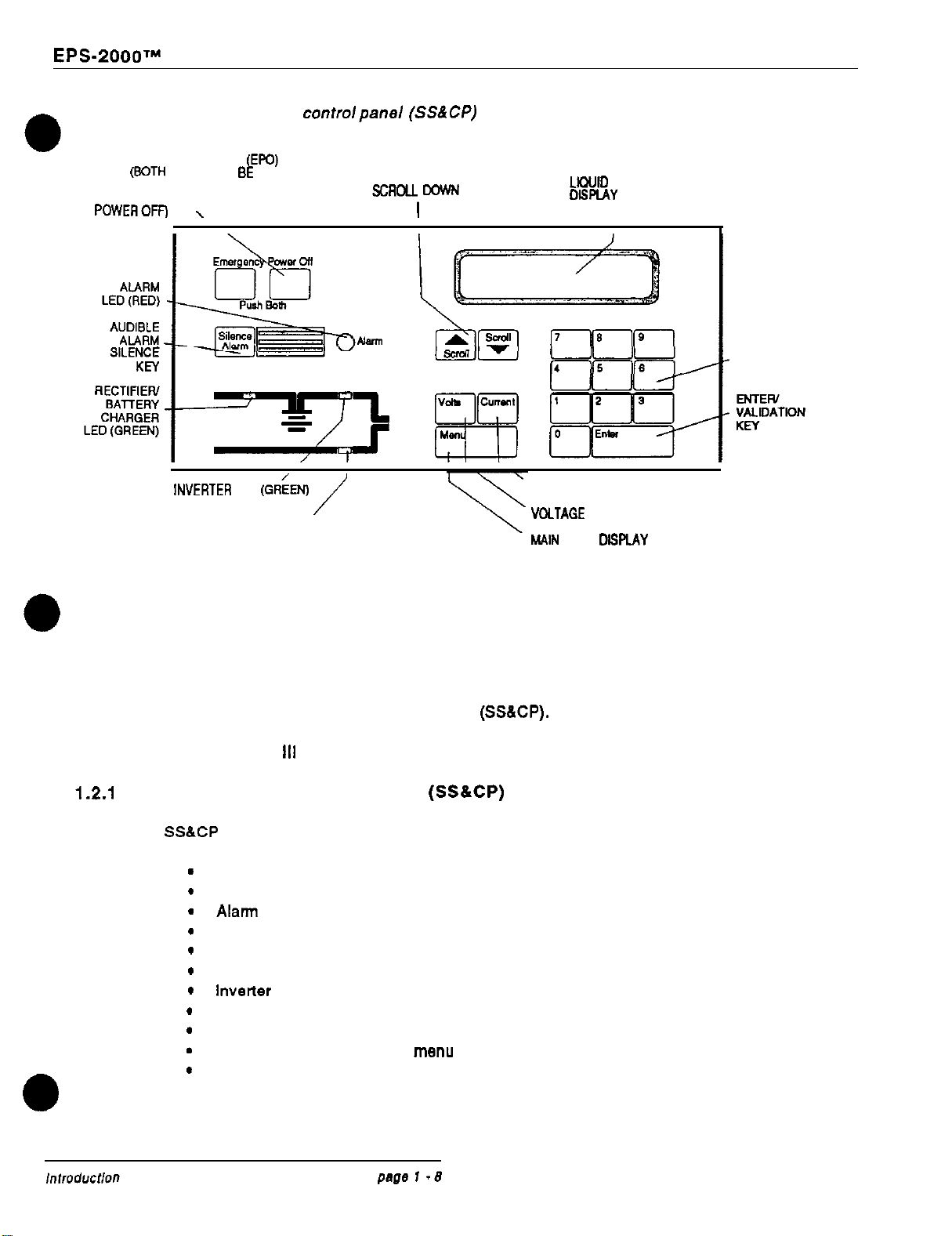
Figure 4: System status and
controlpanel
(SSACP)
EMERGENCY POWER OFF (EFfJ)
KEYS (BOTH KEYS MUST BE
PRESSEDSIMULTANEOUSLY
TO INITIATE AN EMERGENCY
POWEROFF)
\
SCRCU UP AND
SCRC4.L DOWN KEYS
I
LkXJlD CRYSTAL
DISPLAY
(LCD)
I
+++==j
4 5
,+
NUMERIC KEYS
lN”ERTER
LED
(GR;EN)
/
CURRENT (AMPERAGE) MEASUREMENT KEY
LOAD ON BYPASS LED (GREEN) VOCTAGE MEASUREMENT KEY
MAIN MENU
DlSf’lAY
KEY
1.2 Programmable controls and indicators
All EPS-2000 programmable controls (excluding circuit breakers and non-automatic switches) are
located on the system status and control panel
(SS&CP).
These controls and other program-
mable functions and parameters are accessed through the built-in EPS monitor software, de-
scribed in Section
III
-OPERATION.
1.2.1
System status and control panel
(SS&CP)
The
SS&CP
is shown in Figure 4. It contains the elements listed below:
.
.
.
.
.
.
.
.
.
.
.
Liquid-crystal display (LCD)
Audible alarm silence key
Alarm indicating LED
Scroll up and scroll down keys
Ten-digit (0 to 9) keys
Rectifier/battery charger status indicating LED
lnverter status indicating LED
Voltage measurement key
Current measurement key
Entry validation or return to menu key
Emergency power off (EPO) keys (two; must be pressed simultaneously
to initiate the emergency power off function)
Owner’s Manual
I
CAUTION
f
The emergency Power off (EPO) keye are to be used during emergency
situations only, where a hazard to pereonnei or equipment
exists,
such
t
as during a fire. DO NOT USE THE EPO TO TURN THE UPS ON OR OFF;
follow the procedurea listed in Section iii -OPERATION, for turning on
end off the rectifier/battery charger and
inverter.
I
Detailed descriptions of the
SS&CP
controls and indicators, their operation, and operation of the
EPS monitor software are provided in Section iii
-
OPERATION.
1.2.2 Circuit breaker
The main ac input circuit breaker
(al)
is located inside the EPS-2000 enclosure, and can be
accessed by opening the right front enclosure door.
Ql
serves to
connect
and disconnect the
EPS-2000 UPS from its input power source.
Your configuration may have additional circuit breakers and non-automatic switches housed in
optional modules such es the ACA-2000 auxiliary cabinet, the BPA-2000 battery system, and
the SDC-2000 site distribution cabinet. See the manuals for the respective module to learn
more about the controls located in these cabinets. See also Appendix B for typical EPS-2000
system configurations.
1.3
Specifications
This section presents electrical, mechanical. and environmental data for the EPS-2000 UPS
product line.
1.3.1 AC input ratings
Voltage:
206,220 or
460
VAC ( see Table 1 for 50 to 60
kVA
and
460
VAC for 100
&125 kVA and other voltages)
Frequency:
60 Hz
f
5%
Phases:
30 (rotation must be A,
8.
C)
Wires: 3 wires plus ground
(480/600
VAC models); 4 wires plus ground (206
VAC)
Current: Refer to Table 2, nominal ac input current
Power factor: 0.94 lagging
1.3.2 AC output ratings
Voltage:
Frequency:
Phases:
Wires:
206,
220 or
460
VAC
f
1% for all conditions of line, load,
and temperature (see Table 1 for 50 to
80
kVA and
460
VAC for 100
B
125
kVA)
60 Hz
f
0.1% (when internally synchronized)
30 (rotation must be A, B, C)
3 or 4. The UPS inverler output is a Wye configuration wfth the netitrai
grounded. A three-wire Delta load can be connected to the UPS output,
but the phase connections cannot be grounded
EPS-2000TM
Uninterruptible Power
System
Current:
Refer to Table 2. UPS output current at specified nominal output voltage
Power Factor: 0.8 lagging
Overload
characteristics: Applies to the UPS output when operating from either the bypass or the
UPS inverter output:
125% for 10 minutes
150% for 1 minute
Overloads in excess of 150% or exceeding the overload time periods
previously indicated will cause the load to be transferred from the UPS
invener output to the bypass, provided that the two sources are synchro-
nized. Once the load is transferred to the bypass source after exceeding
the time periods previously indicated. the timed periods will start again for
operation on the UPS static switch. If the load does not return to less
than the unit’s full load rating prior to completing the timed overload
periods. the load will be disconnected.
Dynamic
characteristics: Peak voltage deviation on the UPS inverter output is listed below for the
conditions indicated:
50% step load change.
f
3% maximum
100% step load change.
f
5% maximum
Dynamic
response: The UPS inverter output voltage returns to
f
1% of nominal within one
cycle after experiencing a 100% step load change
1.3.3 Battery characteristics
For detailed information on the BPA-2000 battery subsystem. refer to the BPA-2000 owner’s
manual (EPE part number
8&141602-00).
Nominal dc voltage:
480
vdc
DC voltage range:
390
-
545 Vdc
Maximum
fault clearing
current:
5,000 Amperes
Overcurrent protection
device rating:
10,000 Amperes

Owner’s Manual
1.3.4 Mechanical characteristics
Weight:
1,023 kg (2.250 Ibs)
Dimensions:
Height: 1,440 mm (56.66 inches)
Width: 1 ,143 mm (45.00 inches)
Depth: 617 mm (32.16 inches)
Finish: Tri-color gray
1.3.5 Environmental characteristics
Altitude: Operating: sea level to 1,219 meters (sea level
to 4,000 feet)
Non-operating
and storage:
sea level to 10.000 meters (sea level to 32,600 feet)
Temperature: Operating:
O”
C. to 40” C.
(32O
F. to 104’ F.)
Non-operating
and storage:
-25’
C. to
70’
C.
(-13O
F. to
158O
F.)
Relative
humidity:
10 to 90%. non-condensing
Recommended
environment:
20°
to
25O
C.
(66O
to 77’ F.); 50% relative humidity; computer room or
other temperature- and humidity-controlled environment
Audible
noise level:
less than 60
dB
(‘A’ scale)
1.4 EPS-2000 options
Options available for the EPS-2000 UPS are presented in Appendix A
-
Options. Not all options
can be field installed; consult your EPE Technologies dealer for further information.

EPS-2000TM
Uninterruptible Power System
(This page
/eft
blank intentionally.)
Other manuals for EPS-2000 Series
2
This manual suits for next models
5
Table of contents
Other EPE UPS manuals


