EPE EPS-2000 Series User manual

EPS-2000” 10 to 40
kVA
Uninterruptible power system
Owner’s manual

IMPORTANT SAFETY INSTRUCTIONS
SAVE THESE INSTRUCTIONS-This manual contains important instructions for
models
EPS-2010 (10
kVA).
EPS-2015 (15
kVA),
EPS-2020 (20
kVA),
EPS-2030 (30kVA)and EPS-2040
(40
kVA)
that must be followed during installation, operation, and maintenance of the UPS and its
batteries. See page 4-7 for Battery Safety Instructions.
I
f
WARNING
OPENING ENCLOSURES EXPOSES HAZARDOUS
VOLTAGES. ALWAYS REFER SERVICE TO QUALIFIED
.PERSONNEL ONLY. I
f
NOTE
As standards, specifications, and designs change from time to time.
l
please ask for confirmation of the information given in this publication.
I
NOTE
I
f
This equipment generates and uses radio frequency energy, and if not
installed and used in strict accordance with the manufacturer’s instruc-
tions, may cause interference to radio and television reception. It has
0
been type tested and found to comply with the limits for a Class A
computingdeviceinaccordance
with thespecifications in Part 150f FCC
I
Rules, which
aredesignedto
provide reasonable protection against such
interference in a residential installation. However, there is no guarantee
that interference will not occur in
a
particular installation.

EPS-2000” 10 to 40
kVA
Uninterruptible power system
Owner’s manual
for service
call:
1
-
800 -GETS
-
EPE
66-141024-00
NC
4/92
Copyrighl
0
1992 EPE Technologies. Inc.
All rights reserved. Printed in U.S.A.
1660
Scenic Avenue
Costa Mesa. CA 92626
(714) 557
-
1636
1
EPS-2000”
IO
to 40
kVA
Uninterruptible power system
Owner’s manual

Owner’s Manual
ii
iii
vi
vi
l-l
1-2
l-5
l-5
l-6
l-6
I-6
l-7
l-7
l-9
l-8
l-8
l-8
l-9
1-9
1-9
1
-
12
l-12
l-12
l-12
l-13
l-13
l-13
l-13
1.13
l-13
l-13
Saiety
Information
WaMlty
COW3ltS
List of Illustrations
List of Tables
Section I-INTRODUCTION
1.0 Scope
1.1
System Description
1.1
.l
Model Number Format
1 .1.2 Rectifier/Battery Charger
1.1.3
Static
Invwter
1 .1.4 Static Switch
1 .1.5 Maintenance Bypass
1.2 Programmable Controls and Indicators
1.21
System Status and Control Panel
(SSACP)
1.3
Specifications
1.3.1 AC Input Ratings
1.3.2
Bypass AC Input Ratings
1.33
lnwter
AC Output Ratings
1.3.4
Battery
Characteristics
1.3.5 Environmental Characteristics
1.3.6 Other Characteristics
1.4
Options
1.4.1 Sits Distribution Center (SDC)
1.42
Auxiliary Cabinet Assembly (ACA)
1.4.3 BATTERY PAC Assembly (SPA)
1.4.4 Remote Monitor (RM)
1.4.5 Remote Alarm Panel
1.4.6 Remote Communications Link
1.4.7 Modem
1.4.8
Remote Emergency Power Off (REPO)
1.4.9
DC Ground Fault Indication
1.4.10 Smoke/High Temperature Warning (BATTERY PAC)
Conlen,*
Paw
1
EPS-2000”
Uninterruptible Power System
2-1
2-1
2-1
2-2
2-2
2-3
2-4
2-5
2-5
2-5
2-10
2.10
2.10
2-10
2.10
2-11
2-11
2.12
2.15
2-15
2-15
2-16
2.16
2.17
2-17
2-19
2.19
2-19
2-20
2-20
2-20
2
*
21
2-21
2
-
22
Section II -INSTALLATION
2.0 scope
2.1 Receiving
2.2 Handling
2.3 Storage
2.4 Prerequisites to the
InstaffatiOn
2.5 Installation Procedure
2.5.1
Air Fitter Installation
2.52 AC Input Connections
2.53 Bypass AC Input
(MAINS2)
Connection
2.5.4 UPS Output Load Connection
2.5.5 Battery Connections
2.5.6
Controwlntetface
Wiring
2.5.6.1 BPA or External Battery Disconnect Switch
(TBl)
2.5.6.2
Contact Closure Control Wiring
(TBZ)
2.5.6.3 Remote Interface Panel Wiring (TB3)
2.7 Start-Up Procedure
2.7.1 Checks Prior to UPS Start-Up
2.7.2 UPS Initial Start-Up Procedure
2.7.3 Anomalies
2.8 Tests After Initial Start-Up
2.9.1
Start/Stop Test
2.8.1.1
Rectifier/Battery Charger
2.8.1.2
lnverter
2.9.2
On Battery Operation Test
2.9.3
Manual Bypass Operation
2.9.4 Emergency Power Off (EPO)
2.9.5
Site
Environment
Test/External
Contacts
2.8.5.1
Battery Ventilation Fault
2.8.5.2 Remote Emergency Power Off (REPO)
2.8.5.3
External Contact Closures
2.8.5.4 Auxiliary Cabinet Fault Contact Closure
2.9 Voltage and Current Measurements
2.9.1 Voltage Measurements
2.9.2 Current Measurements
Owner’s Manual
3-1
3-1
3-4
3-4
3-5
3-5
3-6
3-7
3-6
3-6
3-9
3-9
3-10
3-10
3-13
3-15
3-20
3-22
3
-
22
3
-
22
3
-
23
3-24
3-25
3-27
3.27
3
-
27
3
-
27
3
-
28
3-26
3
-
26
3
-
29
3.29
3-30
3.0 scope
3.1 System Status and Control Panel (SS&CP)
3.2
Controls
3.2.1
Eleciro-Mechanical
Controls
3.2.2 Programmable Controls
3.3
EPS Monitor
3.3.1 Instructions
3.3.2 Menus
3.3.2.1 Start-Up
3.3.2.2
Inverter
OrKlff
3.3.2.3 Display Contrast
3.3.2.4 Battery Transfer Test
3.3.2.5 Bypass Procedure
3.3.2.6 Commands
3.3.2.7 Diagnostics
3.3.2.6
Personalizatian
3.3.2.9 Communication
3.4
Operating Modes
3.4.1 Automatic Operating Sequences
3.4.1.1 Normal Operation
3.4.1.2 On
Batiery
Operation
3.4.1.3 Input Power
Restored/Battery
Charging
3.4.1.4 UPS
lnverter
Shut-Down or Major Overload
3.4.2 Manual Operating Sequences
3.4.2.1 Rectifier/Battery Charger Start or Stop
3.4.2.2 UPS
lnvefter
Stat
or Stop
3.4.2.3 UPS Isolation for Maintenance
3.4.2.4 Returning the UPS to Normal Operation
3.5
Alarm Conditions
3.5.1
Minor Alarms
3.5.2 Major Alarms
3.5.2.1 Rectifier/Battery Charger
Major Alarms
3.5.2.2 UPS
lnverter
Major Alarms
Section IV
-
MAfNTENANCE
4-1
4.0
scope
4-t
4.1 Preventive Maintenance
4-2
4.2
General Diagnostic Capability
4-2
4.3
Component Replacement
4-2
4.3.1 Replacing Plug-In Power Modules
4-3
4.32
Replacing Printed Circuit
Assemblies (PCAs)
4-4
4.4
Replacement Parts
4-7
4.5
Battery maintenance
Glossary. 1
Glossary
EPS-2000m
UninterruDtible
Power
SYStefII
List of Illustrations
P=W
Figure
Title
l-l
1
l-2
2
1-3 3A
1-4
38
1-9
4
2-1
5
2-2
6
2-4
6
2-6
9
2-9
10
3-1
11
3.22
12
3-23
13
3
_
24
14
3-25
15
3.26
16
3.27
17
List of Tables
EPS-2000~ Pictorial
EPS-2000M UPS Single Line Diagram
EPS-2000m
UPS Major Internal
Components
-
10. 15. and 20
kVA
Models
EPS-2000” UPS Major Internal
Components
-
30 and 40
kVA
Models
System Status and Control Panel
(SSKP)
Handling
Bottom View. 10 to 40
kVA
Models
Right Side Cable Access
Wiring Area
Wiring Detail
System Status and Control Panel (SSSCP)
Power Flow
-
Normal Operation
Power Flow
-
Emergency Operation
Battery Charge Cycle
Power Flow
-
UPS
lnverter
Shut-Down or Major Overload
Overload Curve
Power Flow
-
UPS Maintenance
l-12
1
Standard Models
2-7
2A
Cable Sizing Data, 60 Hz Models
2-6
26 Cable Sizing Data, 50 Hz Models
4-5 3A Replacement Parts
-
EPS4010,
EPS-2015, EPS-2020
4-6
36 Replacement Parts
-
EPS-2030, EPS-2040

Owner’s Manual
1.0 scope
This manual provides technical information re-
quired for the installation, operation, and main-
tenance of the
EPS-2000m
Uninterruptible Power
Supply (UPS) System. Please read this manual
thoroughly before installing or operating the
EPS-
ZOOOW
equipment. The manual is divided into
four sections:
Section I
-
Introduction
This section serves as an introduction to the
manual and the
EPS-2000~
series
of UPS
products rated 10 to 40
kVA.
The UPS system
is described, followed by specifications for
standard models, an introduction to controls
and indicators, and a description of available
options.
Section II
-
Installation
This section explains procedures for receiving.
handling, and storing the equipment,
prerequisites to the installation procedure, in-
stallation, and equipment start-up procedures.
Introduction
Section
Ill
-
Operation
This section describes the
EPS-2000m
System
Status and Control Panel
(SSKP),
including
programmable controls and indicators. electro-
mechanical controls. UPS operating modes, and
system
alsrm
conditions.
Section IV
-
Maintenance
This section describes preventive maintenance
procedures, diagnostic capabilities of the UPS
system, and includes a listing of replacement
parts for the various UPS models.
In the rear of the manual is a glossary which
provides definitions for terms used within the
text. An Index makes it easy to find topics
of interest.
Door Lock ,
Air Filter
(Behind Screen.
Beneath Enclosure) \
System Status and
Control Panel
(SS&CP)
Circuit Breakers
(Behind
Door)
EPS-2000”
Uninterruptible Power System
Figure 2:
EPS-ZOOOTM
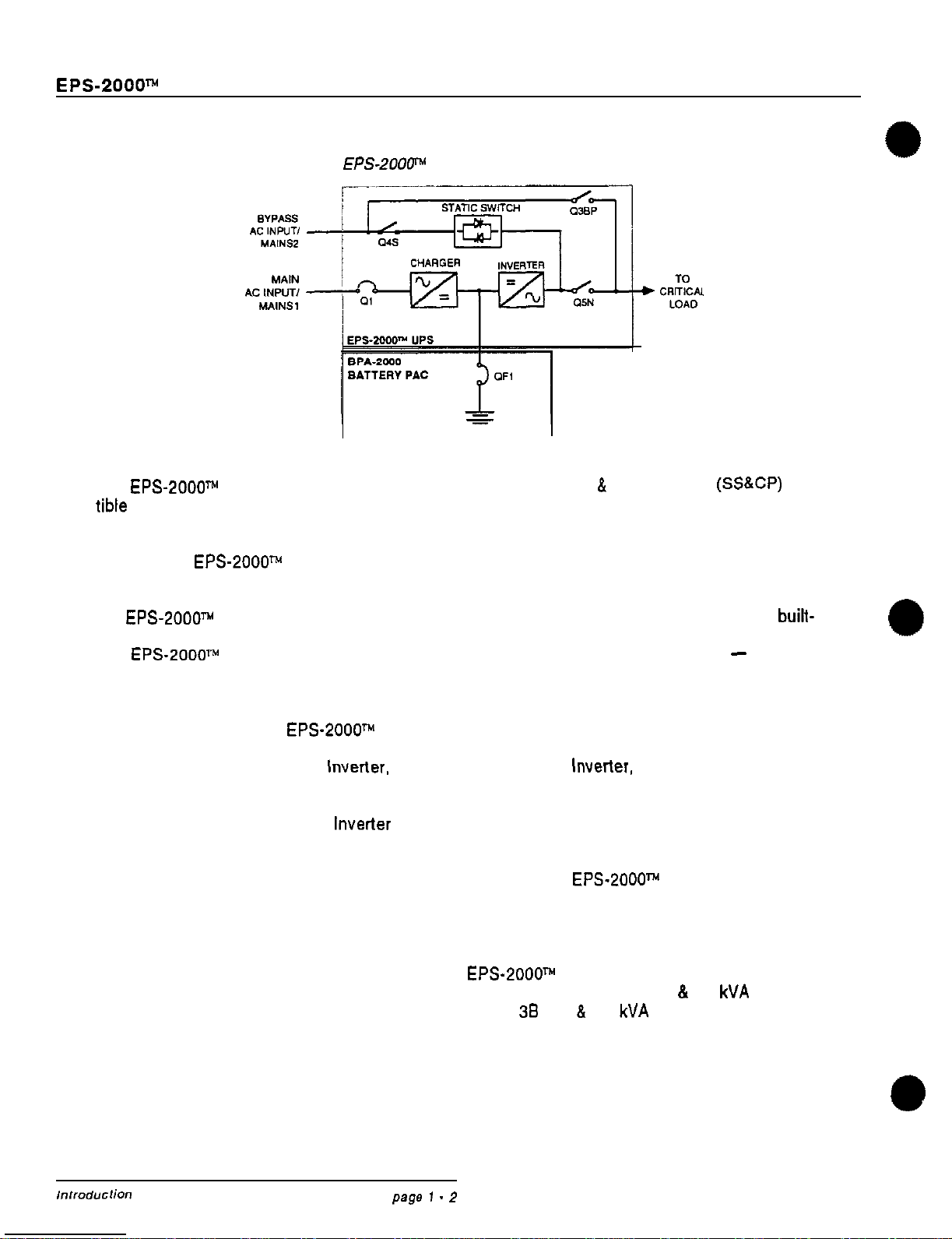
UPS Single Line Diagram
1.1 System Description
The
EPS-2000~
is an on-line static uninterrup
tible
power supply (UPS) system, designed to
protect critical loads from anomalies normally
encountered on a building’s power distribution
system. The
EPS-2000m
UPS and its auxiliary
equipment can be installed in a computer room
or an equipment room. Figure 1 is a pictorial of
the
EPS-2000TH
UPS System.
The
EPS-ZOOOW
UPS and its auxiliary equip-
ment are listed by Underwriter’s Laboratories,
Inc. (UL).
Major components of the
EPS-2000m
include a
Rectifier/Battery Charger, a transistorized pulse
width modulated (PWM) Static
Inverter,
a con-
tinuous duty rated Static Switch which automati-
cally transfers the load to and from the bypass
AC input source and the UPS
lnverter
output,
an internal Maintenance Bypass function which
is comprised of three separate switches that
allows the critical load to be operated from the
utility source while the UPS output is isolated
for service, and a battery system housed in an
external matching enclosure.
A System Status
&
Control Panel
(SS&CP)
pro-
vides controls to select system operation, and
indicators which allow system performance to
be monitored. A liquid crystal display (LCD) is
used to display system operating parameters,
provide step-by-step operating instructions to
the system operator, and provide a diagnostic
capability to assist in troubleshooting. The
built-
in EPS Monitor software is programmed to dis-
play messages in five languages
-
English,
French, German, Spanish, and Italian.
The EPS-2000” uses microprocessors to pre-
cisely control operation of the Rectifier/Battery
Charger, transistorized pulse width modulated
(PWM) Static
Inverter,
and Static Switch to in-
sure optimum performance for all line, load, and
operating conditions. In addition, a micropro-
cessor-based diagnostic system assists in trouble-
shooting faulty assemblies for replacement, to
minimize service time. Modular construction
throughout the
EPS-2000m
UPS facilitates main-
tenance of the system.
A single-line diagram of the EPS-2000”” UPS
system is shown in Figure 2. The location of the
EPS-2000m
UPS major internal elements is
shown in Figure 3A (10. 15.
&
20
kVA
Models),
Figure
38
(30
8
40
kVA
Models).
,“,,od”crio”
page
1
-
2

Owner’s, Manual
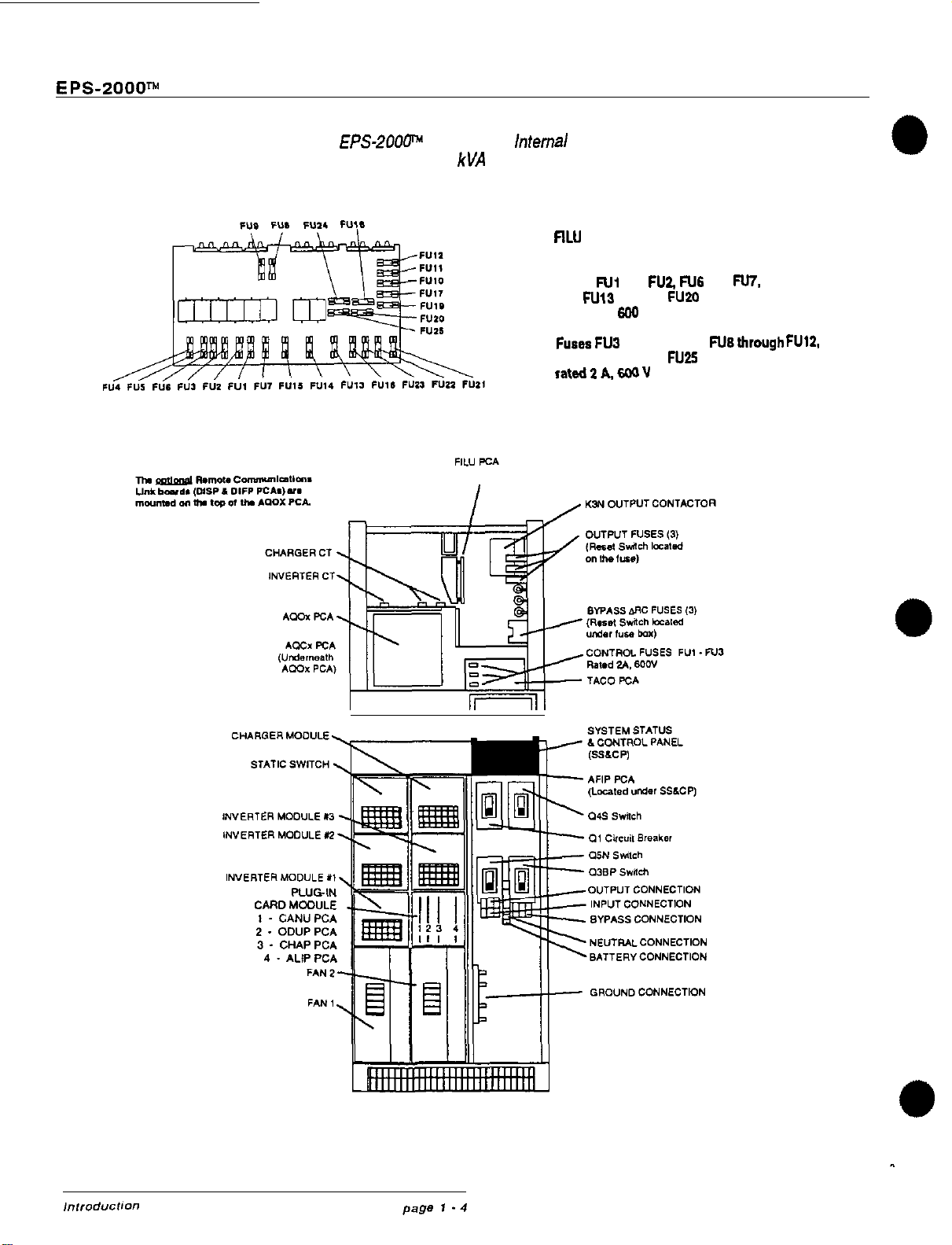
Figure 3A:
EPS-2OOp
UPS Major
lnfemal
Components
IO,
15.
and 20
kVA
Models
FILU PC Assembly
Conbol
Fuse
Locations
Fuass
FUI
and
FUZZ,
FU6
and
FE’,
and
N13
through FUZO
rated 5
4 600 v
Fuses FU3 through FU5, FU6 through
FUIZ,
and
FUZI
through FU25
rated2 A. 600 V
F”3
I
I,
EPS-2000m
Uninterruptible Power System
Figure 38:
EPS-2OOF
UPS Major
lntemal
Components
30 and 40
kVA
Models
flLU
PC Assembly
Control Fuse Locations
Fuses
Ni
and
FU2
FlJ6
and
M.
and
FM3
through FUZO
rated 5 A,
600
V
Fuses
F”2
through FU5,
FU8through
FU12.
end FU21 through FU25
rated21/wJV

Owner’s
Manuai
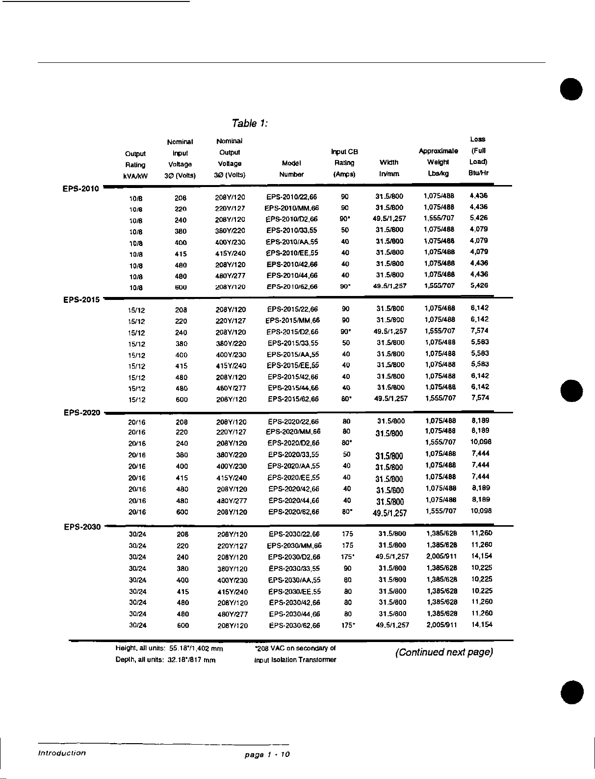
1.1.1 Model Number Format
The Model Number Format used for the EPS- Standard Models and characteristics are listed in
2000TM
series of UPS follows: Table
1.
EPS
-
2 XXX
/
Vi
V,,
5
F,
output Power
Ratina
in
kVA
010
I10
015
=
15
020
= 20
030
=
30
040
=
40
FW.WenC~
m
2
.208
5=50
3
=380
6
=
60
4
=4so
6
=6W’
M
=220
D
=240’
A
=4o0
E
=415
‘Not available as an
output voltage
1.1.2 Rectifier/Battery Charger
The Rectifier/Battery Charger consists of:
l AC Input Circuit Breaker
(al):
The AC
*
Input Circuit Breaker provides mechanical
isolation and electrical protection for the in-
put of the UPS.
-
Input Autotransformer: The Input Autotrans-
former is used to match the external AC
input source to that internally required for
the UPS. .
Power Module: The Power Module is a
plug-in unit which converts incoming AC power
lo
a regulated DC output voltage. The regu-
lation is carried out by controlling the
SW
conduction angles, allowing the Rectifier/
Battery Charger to supply a stable DC volt-
age
(2
1%). The DC voltage is filtered by a
capacitor bank.
DC Shunt: The DC Shunt is used to moni-
tor the battery charge current and provide
data for regulating the DC voltage at the
desired level. Battery current is normally
limited to 10% of the Ampere-Hour (Ah) rat-
ing of the battery siring.
EPS-2000~~
Uninterruptible Power System
1.1.3 Static lnverter
The Static lnverler consists of:
Power Module: The Power Module is a
plug-in unit, used
lo
chop the DC voltage to
obtain the PWM waveform at the primary of
the output transformer. A single power module
is used for UPS systems having an output
rating of 20
kVA
or lower. UPS systems
rated above 20
kVA
use three power mod-
ules, one module per phase.
lnverter Transformer: The lnverter Trans-
former is a full isolation transformer which
provides input/output electrical isolation for
the UPS, provides the required output volt-
age, and provides the required inductance
for the AC output filter.
AC Output Filter: The output filler is used
to achieve a computer grade sine wave
output voltage waveform, with a Total
Harmonic Distortion (THD) of 4% maximum
(3% typical).
1.1.4 Static Switch
The Static Switch transfers the load from the
UPS lnverter
output
to the bypass AC input source,
or from the bypass AC input source to the UPS
lnverter Output, without any interruption to the
load (provided that the UPS lnverter output is
synchronized lo the Bypass AC Input source).
These transfers take place automatically upon
lnverter start-up or shut-down. The Static Switch
is rated for continuous duty, and is of plug-in
construction for ease of maintenance.
The ARC circuit network protects the Static Switch
against high voltage spikes and surges by
absorbing the excess
enerov.
The ARC circuit
network
ib
protected by
fus&.
and any failure
of
these fuses will be displayed on the
SS&CP
LCD.
1.1.5 Maintenance Bypass
The internal Maintenance Bypass function con-
sists of three switches which, when operated
as specified, provide a make-before-break transfer
of the load from the UPS lnverler output to the
bypass AC input source, or from the bypass AC
input source to the UPS lnverler output. This
feature allows the critical load to be operated
from the utility power source while the UPS
lnverter output is isolated for maintenance.
The three internal Maintenance Bypass non-auto-
matic switches are designated as:
A. Bypass (MAINS2) Input
(04s)
B. UPS Output Isolation
(Q5N)
C. Maintenance Bypass
(Q3BP)
Correct operation of the three switches is shown
on the Liquid Crystal Display (LCD), located on
the System Status
&
Control Panel
(SS&CP)
as
part
of the procedure for
star+up
or shut-down
of the equipment.
Owner’s Manual
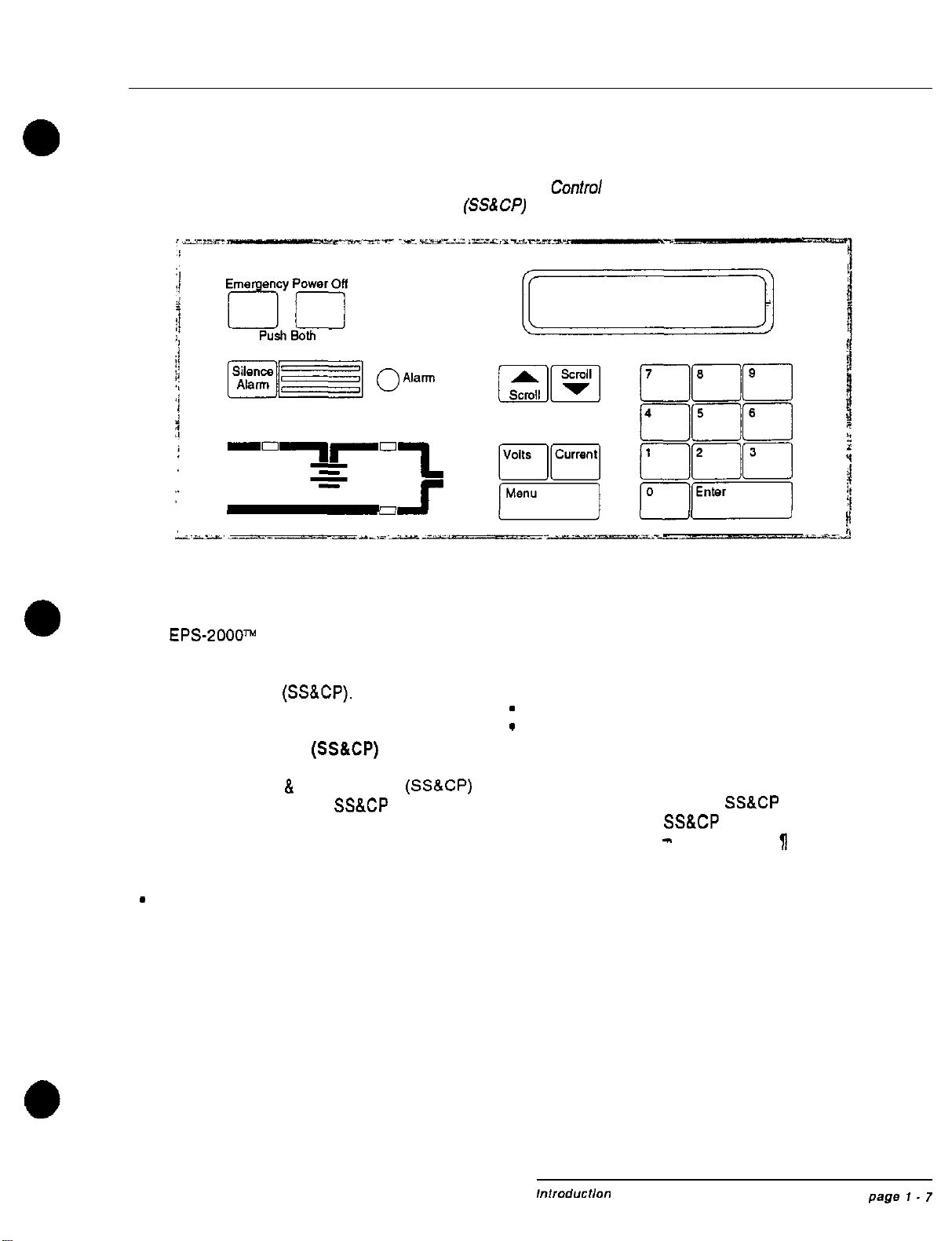
figure 4: System Status and
Confro/
Panel
(SSS CP)
1.2 Programmable Controls and Indicators
All
EPS-2000w
Programmable Controls (exclud-
ing circuit breakers and non-automatic switches)
and Indicators are located on the System Status
and Control Panel
(SS&CP).
1.2.1 System Status and
Control Panel
(SS&CP)
The System Status
&
Control Panel
(SS&CP)
is
shown in Figure 4. The
SS&CP
contains the
elements listed below:
l Liquid Crystal Display (LCD)
l Audible Alarm Silence keypad
-
Alarm Indication
l Scroll Up keypad
l Scroll Down keypad
l Ten Digit (0 to 9) keypads
l Rectifier/Battery Charger Status Indicator
l lnverter Status Indicator
l Load on Bypass Indicator
l Voltage Measurement keypad
l Current Measurement keypad
-
Main Menu Call keypad
-
Entry Validation or Return To Menu
keypad
l Emergency Power Off (EPO) keypads
Detailed descriptions of the
SS&CP
indicators
and the use of the
SS&CP
keypads are pro-
vided in Section Ill
-
OPERATION,
g
3.1.
EPS-2000”
Uninterrupttble
Power System
1.3 Specifications
1.3.1 AC Input Ratings
Refer to
1
1
.I
.I
for nominal Voltage (VAC)
values available.
Voltage:
Frequency:
Phases:
Wires:
Current:
As specified, nominal
plus (+)
lO%/minus
(-)
15%
Nominal, plus (+) or
minus
(-)
5%
Three, phase rotation A,
B,
C
Three plus equipment ground
See Table 2 (page 2
-
7).
Nominal AC Input Current
Power Factor: 0.82 lagging minimum at full
load output, nominal input voltage, and normal
float voltage on battery
1.3.2 Bypass AC Input Ratings
Voltage: Must match UPS nominal
output voltage
*
10%
Frequency Window: Nominal plus
(t)
or
minus
(-)
0.25, 0.5, 0.75, or 1.0 Hz. Standard
setting for bypass input frequency window is
+
0.5 Hz unless otherwise specified when or-
dered. The Frequency Window can be changed
after the unit is installed, but requires a visit by
an EPE authorized Customer Support Services
(CSS) representative to modify the equipment,
Contact
EPE’s
Customer Support Services or-
ganization for further information.
Phase: Three, phase rotation A, B, C
Wires: Four wire WYE
Current: See Table 2 (page’2
-
7). UPS
Output and Bypass AC Input Current at speci-
fied nominal output voltage.
Power Factor: load dependent
1.3.3 lnverter AC Output Ratings
Refer to
j)
1
.l.l
for nominal Voltage (VAC)
values available.
Voltage: Nominal value
f
1% for all
conditions of line, load, and temperature
Frequency: Normally synchronized to the by-
pass AC input source (when available); other-
wise the output frequency is the nominal value
*
0.1%.
Phase: Three, phase rotation A,
8,
C
Wires: Three or four. The UPS lnverter
output is a WYE configuration with the neutral
grounded. A three wire DELTA load can be
connected to the UPS lnverter output. but the
phase connections cannot be grounded.
Current: See Table 2 (page 2
-
7),
UPS
Output and Bypass AC Input Current at speci-
fied nominal input voltage.
Power Factor: The UPS lnverter output is rated
at full
kVA.
0.8 power factor lagging load.
Slew Rate: The rate of change of the UPS
Inverter
output frequency, (a) while tracking within
the frequency window (see Bypass AC Input
Ratings
-
Frequency Window), (b) when syn-
chronizing to the bypass AC input source, or(c)
when going to a free running condition after
losing AC input power, is 1
Hz/secmaximum.

Owner’s Manual
1.3.5 Environmental Characteristics
Overload Characteristics: Applies to the UPS Temperature:
Output when operating from either the bypass
AC input source or the UPS lnverter output: Operating Range: 0” c. to
+40”
c.
(Excluding battery)
125% for 10 minutes
150% for 1 minute Non-Operating and Storage:
Overloads in excess of 150% or exceeding the -25” C. lo
+70”
C
overload time periods previously indicated will
cause the load lo be transferred from the UPS
lnverler
output to the bypass AC input source, NOTE
provided the sources are synchronized. Once
the load is transferred to the bypass AC input
f
Batteries should only be stored
source after exceeding the time periods
previ-
in a fully charged condition at
ously
indicated, the timed periods will
start
again temperatures less than
80”
F.
for operation on the UPS Static Switch. If the
0
(26.7” C.)
load does not return to less than the unit’s full
load rating prior to completing the timed over-
load periods, the load will be disconnected. Relative Humidity: 0 to
95%,
non-condensing
Dynamic Characteristics: Peak voltage devia-
tion on the UPS
Inverter
output is listed below Recommended Environment: Computer Room
for the conditions indicated: or other temperature controlled environment.
50% step load change Recommended Temperature: 20 to 30” C.
*
3% maximum (Battery protection time is based on a 25°C.
ambient temperature)
100% step load change
2
5% maximum Recommended Relative Humidity: 50%
Dynamic Response: The UPS
lnverter
output 1.3.6 Other Characteristics
voltage returns lo
k
1% of nominal within one
cycle after experiencing a 100% step load change Audible Noise Level:
1.3.4 Battery Characteristics 10 to 40
kVA
ratings:
5
60
dBA
DC Voltage Range: Physical Dimensions:
325 Vdc minimum Height:
55.16”/1,402
mm
436 Vdc maximum Depth:
32.10”1017
mm
Width: See Table
1
DC Current Required: Weight: See Table 1
See Table 2 (page 2
-
7),
Maximum
Battery Current.
EPS-2000” Uninterruptible Power System
Table
I:
Standard Models
31
s/800
49.5n.257
31
.moo
31.5moo
31.5moo
31.5moo
31.5moo
49.511257

Owner’s Manual
Table
1:
Standard Mode/s (continued)

EPS-2000~
Uninterruptible Power System
1.4 Options
1.4.1 Site Distribution Center (SDC)
The Site Distribution Center (SDC) provides the
means of distributing powerfrom the EPS-2000”
UPS
svstem
to the user’s intended equipment.
The
S&Z
is furnished in an enclosure matching
the other
EPS-2000N
series equipment. The
SDC attaches to the right side of the
EPS-2000TM
UPS enclosure, or the right side of the Auxiliary
Cabinet Assembly (ACA). EPE provides all the
necessary hardware, power and control cables.
and the instructions for the task. The customer
is responsible for installation of the equipment
in the field.
1.4.2 Auxiliary Cabinet Assembly
(ACA)
The Auxiliary Cabinet Assembly (ACA) provides
the means for incorporating three optional el-
ements into the
EPS-2000N
UPS system. The
ACA attaches to the right side of the EPS-2000”
UPS enclosure. EPE provides all the necessary
hardware, power and control cables, and in-
structions for the task. The customer is respon-
sible for installation of the equipment in the field.
The empty ACA enclosure alone will accommo-
date top cable entry when required, which may
occur if the UPS is installed in an equipment
room with limited space available. Alternately,
the ACA may include an input isolation trans-
former, or an input harmonic current filter or
both depending on which options are purchased.
The input isolation transformer provides com-
plete electrical isolation between the utility line
and the input of the UPS (Rectifier/Battery Charger
and Battery), providing extra protection against
electrical noise and ground faults. The input
harmonic current filter limits the amount of har-
monic current fed back on to the input AC power
source to less than 10% when the
EPS-2000m
UPS is operating at full load.
a
isolation transformer as
I
standard equipment.
I
1.43
BATTERY PAC Assembly (BPA)
Each EPS-2000” UPS is furnished with a
BATTERY PAC Assembly (BPA), which contains
a battery having sufficient ampere-hour (A-H)
capacity to
suppori
the UPS and its intended
load for the protection time specified.
An EPE BPA features the use of sealed,
maintenance-free, lead-calcium, recombination
type batteries. The batteries are
maintenance-
free from the standpoint that they do not require
the electrolyte level nor the density of the elec-
trolyte to be checked periodically. However, the
BPAs
do require that the interior of the assem-
bly, including the exterior surfaces of the indi-
vidual batteries, be kept clean and free of all
foreign matter including dust. The integrity (torque)
of the individual battery connections inside the
BPA must be verified annually.
The EPA-2000 series BATTERY
PACs
provide
ready access to the batteries, as they are mounted
on pull-out rack assemblies.
Other manuals for EPS-2000 Series
2
This manual suits for next models
5
Other EPE UPS manuals


