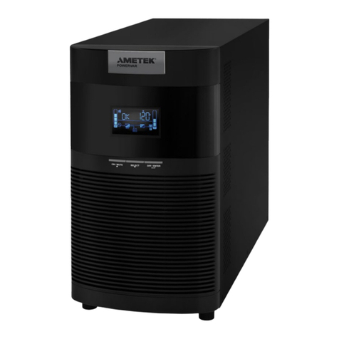
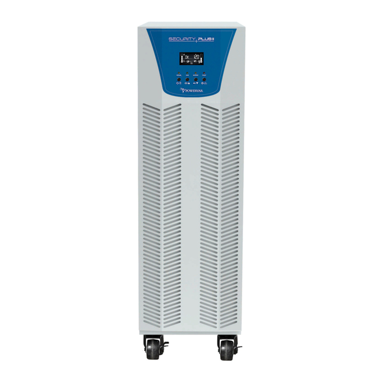
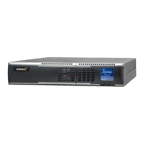
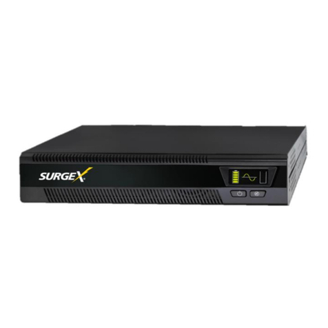
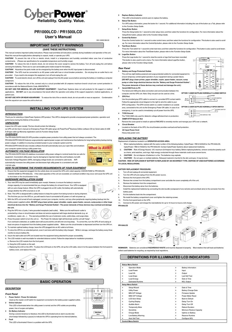
Ametek SURGEX Security Plus II UPS-42100-85R User manual

© 2020 AMETEK Electronic Systems Protection / Technical Support: 1-800-645-9721 / UM-Security-Plus-II-Rev-A
Security Plus II
Online UninterruptiblePowerSupply
UPS-42100-85R
UserManual

User Manual
_________________________________________________________
© 2020 AMETEK Electronic Systems Protection / Technical Support: 1-800-645-9721 / ametekesp.com

User Manual
_________________________________________________________
© 2020 AMETEK Electronic Systems Protection / Technical Support: 1-800-645-9721 / ametekesp.com
TABLE OF CONTENTS
1.0 GENERAL SAFETYINSTRUCTIONS 1
2.0 UNPACKING AND INSPECTION 6
3.0 UPS PANEL LA
YOUT
7
4.0 UPS INSTALLATION (Hardwire Units Only) 8
4.1 Overview
8
4.2 Wiring Diagrams 10
4.3 Circuit Protection Requirements 14
5.0 OPERATION 16
5.1 Button Operation
16
5.2 LED Indicators and LCD Panel 17
5.3 Audible Alarm
19
5.4 Single UPS Operation
20
5.5 Connect Devices to UPS 21
5.6 Charge the Batteries 21
5.7 Battery Mode Operation 22
5.8 Test the Batteries 22
5.9 Turn Off the UPS with Utility Power Supply in AC Mode 22
5.10 Turn Off the UPS Without Utility Power Supply in Battery Mode 23
5.11 Mute the Buzzer 23
5.12 Operation in Warning Status 23
5.13 Operation in Fault Mode 24
5.14 Operation of Changing Charging Current 24
6.0 LCD SETTING 25
7.0 OPERATON MODE/STATUS DESCRIPTION 34
8.0 FAULT CODE
36
8.1 Warning Indicator 36
8.2 Warning Code 37
9.0.
TROUBLESHOOTING
38
10.0. STORAGEAND MAINTENANCE 40
10.1 Storage 40
10.2 Maintenance 40

1
User Manual
_________________________________________________________
© 2020 AMETEK Electronic Systems Protection / Technical Support: 1-800-645-9721 / ametekesp.com
1.0 GENERAL SAFETY INSTRUCTIONS
Warnings in this manual appear in any of four ways:
Use of this equipment in life support applications where failure of this
equipment can reasonably be expected to cause the failure of the life
support equipment
or to significantly affect its safety or
ef
fectiveness
is not recommended. Do not use this equipment in the presence of a
flammable
anesthetic
mixture with air, oxygen or nitrous
oxide.
Connect
your UPS power
module’s grounding
terminal to a
grounding
electrode conductor.
The UPS is connected to a DC energy source (battery). The output
terminals may be live when the UPS is not connected to an AC supply.
Operation
DAN
GE
R
Do not disconnect the earth conductor cable on the
UPS
or the building
wiring terminals at any time as this would negate the protective earth of the
UPS
system and of all connected loads.
DAN
GE
R
The
UPS
system features its own, internal current source (batteries). The
UPS
output sockets or output terminal blocks may be electrically live even if
the
UPS
system is not connected to the building wiring outlet.
W
ARN
ING
In order to fully
disconnect
the UPS
system,
first
press
the “OFF” button
and
then disconnect the mains.

2
User Manual
_________________________________________________________
© 2020 AMETEK Electronic Systems Protection / Technical Support: 1-800-645-9721 / ametekesp.com
NOTE TO USERS
To ensure correct operation of the UPS, please read this instruction
manual carefully. Please keep this manual handy for future reference.
ELECTRICAL HAZARD
AUTHORIZED
PERSONNEL
ONLY
This UPS has dangerously high voltages on both its Input
and output connections. Contact with these voltages may
be life threatening. Please follow the operating instructions
carefully. Please give close attention to the warnings in
this manual and those posted on the UPS. There are no
user serviceable parts inside the UPS. Disassembly and/
or maintenance should only be done by an authorized
professional service technician
IMPORTANT INFORMATION FOR USERS
OF
THIS UNINTERRUPTIBLE POWER
SUPPLY
1. Before operating the UPS or connecting any load equipment,
please ensure the UPS is connected to a properly grounded
electrical supply.
2. This UPS has dangerously high voltages on both its input and
output connections. Contact with these voltages may be life
threatening.
3. Please do not disassemble the covers. There is a risk of electric
shock.
4. In an emergency, immediately turn off the circuit breaker for the
circuit supplying power to the UPS; open DC on battery breaker.
5. This UPS has two power sources. One is the circuit supplying the
UPS with input power. The other is the UPS battery. Prior to any
maintenance, both of these power sources must be disconnected
to ensure that the UPS is de-energized. If only the input power
is disconnected, the UPS can still operate from the battery, and
hazardous voltages may still exist.
6. To prevent damage or a safety hazard, keep the UPS away from
open flame and any other
devices
that may
cause sparks.
7. Do not open or damage individual battery cases as spillage of

3
User Manual
_________________________________________________________
© 2020 AMETEK Electronic Systems Protection / Technical Support: 1-800-645-9721 / ametekesp.com
caustic electrolyte may occur, resulting in danger to life, safety, and
the environment.
8. The charging characteristics of UPS batteries vary by both brand
and type. For this reason, replacement batteries should be of the
same
brand and type
as those specified
by the
manufacturer
.
Using
batteries
other than the brand and
type
specified
by
the
manufacturer may affect the performance
of the UPS. Before installing batteries of different brand or type,
please consult with the manufacturer.
9. The UPS has an internal EMI filter for
purposes
of
enhancing
electromagnetic compatibility with the input mains
supply. This filter
produces leakage
current to earth on the
input mains.
When
selecting a circuit breaker for the branch
circuit supplying power
to the UPS, ensure that the breaker selected is not an ELCB type
circuit breaker that detects earth leakage current.
10. Please contact the manufacturer or an authorized distributor for
any assistance with troubleshooting.
11. The UPS should only be serviced or maintained by a factory
authorized service technician.
12. This UPS meets FCC Class A electromagnetic compatibility
requirements.
13. Depleted batteries must be disposed of in a proper manner
.
Contact your local recycling or hazardous waste center or the UPS
manufacturer for instructions concerning proper disposal.
CAU
TION
Please be careful to observe the following general safety precautions
during operation or maintenance
1. There are no user serviceable parts inside this UPS. Please don’t
remove
the
covers.
This
system
can only be
maintained or
repaired by an authorized SurgeX service technician.

4
User Manual
_________________________________________________________
© 2020 AMETEK Electronic Systems Protection / Technical Support: 1-800-645-9721 / ametekesp.com
2. To improve electromagnetic compatibility (EMC), this UPS has
an input EMI filter, which
produces
potentially
dangerous
leakage
current to ground. Ensure the UPS is connected to a
properly grounded input electrical source. Install this UPS indoors
in an environment that is temperature and humidity controlled.
3. Install this UPS in a dust-free environment.
4. This UPS has two sources of power. Before maintenance is
performed, turn off the branch circuit breaker powering the UPS
and turn off all battery switches.
5. Even with the AC input power supply turned off, the
UPS’s
internal
battery still represents a potentially dangerous source of
high voltage electrical power.
6. If the battery circuit has not been disconnected from the AC
input, dangerous voltage potential still exists between the battery
terminal and the ground terminal.
7. UPS batteries represent a high voltage source and a potential
hazard to personal safety. Please pay attention to proper safety
precautions and use insulated tools during installation.
8. UPS batteries contain corrosive and caustic chemicals. Improper
handling of batteries may lead to the unintended release or
leakage of these substances. Please handle batteries carefully.
9. Condensation may occur when the UPS is moved from a
low temperature, low humidity environment to a warm humid
environment. Condensation may cause UPS damage or hazardous
electrical shock. To ensure the safety of both the UPS and the
personnel around it, make sure that the UPS is installed only after
it has fully acclimated to its installation environment. This UPS
is not intended to be operated in an environment of either low
temperature or high humidity.
10. The DC voltage is still present on the battery fuses even with the
UPS turned off. The batteries must be removed before servicing
UPS.

5
User Manual
_________________________________________________________
© 2020 AMETEK Electronic Systems Protection / Technical Support: 1-800-645-9721 / ametekesp.com
CAU
TION
Ensurethat no liquid or other foreign objects can enter into the
UPS
system.
W
ARN
ING
The
UPS
is to be operated by individuals with appropriate experience.
Standards* Safety
Safety Conformance:
IEC/EN
62040-1, UL1778 (5th Edition)
Safety Markings: cTUVus, CE
* EMI
Conducted
Emission: IEC/EN
62040-2,
FCC PART15 CLASS A
Radiated
Emission: IEC/EN
62040-2,
FCC PART15 CLASS A
*EMS
ESD: IEC/EN
61000-4-2
Level 4
RS: IEC/EN
61000-4-3
Level
3
EFT: IEC/EN
61000-4-4
Level 4
SURGE: IEC/EN
61000-4-5
Level 4
CS:
IEC/EN
61000-4-6
Level
3
Power-frequency Magnetic
field: IEC/EN
61000-4-8
Level 4
Low
Frequency Signals:
IEC/EN
61000-2-2
Warning: This is a product for commercial and industrial application in the
second environment installation restrictions or additional measures may be
needed to prevent disturbances.

6
User Manual
_________________________________________________________
© 2020 AMETEK Electronic Systems Protection / Technical Support: 1-800-645-9721 / ametekesp.com
2.0 UNPACKING AND INSPECTION
Unpack the package and check the contents. The shipping package
contains:
•Quick Start Guide
•One UPS
•One RS-232 cable (option)
•One USB cable
NOTE:
Before installation, please inspect the unit. Be sure that nothing
inside the package is damaged during transportation. Do not
turn on the unit and notify the carrier and dealer immediately
if there is any damage or lacking some parts. Pleasekeep the
original package in a safe place for future use.

7
User Manual
_________________________________________________________
© 2020 AMETEK Electronic Systems Protection / Technical Support: 1-800-645-9721 / ametekesp.com
3.0 UPS PANEL
L
A
YOUT
1. RS-232 communications port
2. USB communications port
3. Emergency power off connector (EPO)
4. Intelligent pocket
5. Charger cooling fan
6. Power stage cooling fan
7. Maintenance bypass switch
8. Input circuit breaker
9. Isolation transformer cooling fan
10. Input / output terminal block connections
11. External battery cabinet connection

8
User Manual
_________________________________________________________
© 2020 AMETEK Electronic Systems Protection / Technical Support: 1-800-645-9721 / ametekesp.com
4.0 UPS INSTALLATION (Hardwired units only)
4.1 Overview
CAU
TION
Installation and wiring must be performed in accordance with local electrical
laws/regulations/codes. Thefollowing instructions should only be executed
by
qualified
professional
personnel.
1. Make sure the mains wire and breakers in the building are suitable
for the rated capacity of the UPS to avoid the hazards of electric
shock or fire.
2. Switch off mains power before installation.
3. Turn off all the connected devices before connecting to the UPS.
4. Remove terminal block cover on the rear panel of UPS, then
connect the wires according to the following terminal block
diagrams:
Rear panel terminal block layout –all
models
Note: Illustration above showing 10-pole block applies to all
models.

9
User Manual
_________________________________________________________
© 2020 AMETEK Electronic Systems Protection / Technical Support: 1-800-645-9721 / ametekesp.com
•1 - 3 are SSOTAP selection (must match mains input / inv
voltage selection)
•4; 5; 6; 7 Next four are outputs as listed -120; 88; 0; +120
•8; 9; 10 Last three are mains power input l1; l2; earth.
CAU
TION
For field wired units, refer to the
tables
below for the
proper cond
uctor
size
and
torque requirements.
Only
copper conductors
are to be
used
for field
wiring
connections.
The
conductors should
be
rated
at least
75°C or
greater. The conductor recommendations listed in the chart below are
intended
for
installations
in North America. For
international insta
llations, please refer to
the local and national electrical codes and standards.
RATING
INPUT
CONDUCTOR
(A
WG)
MIN
MAX
TORQUE
(in-lbs.)
OUTPUT
CONDUCTOR
(A
WG)
MIN
MAX
TORQUE
(in-lbs.)
GROUND
(A
WG)
MIN
MAX
TORQUE
(in-lbs.)
2.0kVA 12 6 20 12 6 20 12 6 20
3.0kVA 12 6 20 12 6 20 12 6 20
4.0kVA 10 6 20 10 6 20 8 6 20
5.2kVA 8 6 20 8 6 20 8 6 20
6.0kVA 8 6 20 8 6 20 6 6 20
8.0kVA 4 1 60 4 1 60 6 4 60
10.0kVA 4 1 60 4 1 60 6 4 60
TABLE 2-4A HIGH VOLTAGE CONDUCTOR SIZE AND TORQUE SPECIFICATIONS
RATING
INPUT
CONDUCTOR
(A
WG)
MIN
MAX
TORQUE
(in-lbs.)
OUTPUT
CONDUCTOR
(A
WG)
MIN
MAX
TORQUE
(in-lbs.)
GROUND
(A
WG)
MIN
MAX
TORQUE
(in-lbs.)
2.0kVA 10 6 20 10 6 20 8 6 20
3.0kVA 8 6 20 8 6 20 6 4 20
TABLE 2-4B LOW VOLTAGE CONDUCTOR SIZE AND TORQUE SPECIFICATIONS

10
User Manual
_________________________________________________________
© 2020 AMETEK Electronic Systems Protection / Technical Support: 1-800-645-9721 / ametekesp.com
4.2 Wiring Diagrams (Hardwired units only)
For North American
applications,
UPS
models
may be
configured
for an
input voltage of 208 or 240 volts at 60 Hz. SSO tap must match
customers utility voltage. Output voltages for these models are available
at 120, 208 (using the 120 & 88 taps) and 240 volts at 60 Hz. See the
table below to connect to the terminal block in Figure 2-5D to achieve the
desired
input and output voltage
configurations.
NORTH AMERICAN CONNECTIONS
INPUT OUTPUT
SSO
VOLTAGE
RATING VOLTAGE
L1 - L2 FREQ VOLTAGE NEURTRAL
BOND FREQ TAP
JUMPER
208 208 60 -120 10.0 88 0 +120 SEE 60 208-(0)
240 240 60 -120 8.0 88 0 +120 DIAGRAM
40 240-(0)
NOTE:
Theneutral to ground bond connection must be properly
connected
for a 50 or 60 Hz
configuration.
For
international applications,
UPS
models
may be
configured
for
an
input voltage of 220, 230 or 240 volts at 50 Hz. SSO tap must always
be set to 240. Output voltage for these models matches the input voltage
at 50 Hz. See the table below to connect to the terminal block in Figure
2-5B to
achieve
the
desired
input and output voltage
configurations.
INTERNATIONALCONNECTIONS
INPUT OUTPUT
VOLTAGE
RATING
VOLTAGE
L1 - L2 FREQ VOLTAGE
NEURTRAL
BOND FREQ
SSO TAP
JUMPER
-- -- -- -- -- -- --
220 220 50Hz 0 -- 110 220
230 230 50Hz 0 -- 115
230
SEE
DIAGRAM
-- --
50Hz 240-(0)
50Hz 240-(0)
240 240 50Hz 0 -- 120 240 50Hz 240-(0)

11
User Manual
_________________________________________________________
© 2020 AMETEK Electronic Systems Protection / Technical Support: 1-800-645-9721 / ametekesp.com
1) 120V and 208V Output
Output wiring –208V & 120V
NOTE 1: SSO Tap
Selectionneeds
to be set to
match
the
input
voltage.
NOTE 2: 208 is obtained by using the 120 and 88 terminals.
NOTE 3: Make sure that the wires are connected tightly to the
terminals.
NOTE 4: Install the output breaker between the output terminal and
the load. The
breaker should
be qualified with
leakage
current protection if necessary.

12
User Manual
_________________________________________________________
© 2020 AMETEK Electronic Systems Protection / Technical Support: 1-800-645-9721 / ametekesp.com
2) 120V and 240V Output
Output wiring –240V & 120V
NOTE 1: SSO Tap
Selection needs
to be set to
match
the
input
voltage. Install a jumper between 0-208V or 0-240V.
NOTE 2: Split phase wiring, load shall be balanced 50 / 50 on each
side of transformer taps.
NOTE 3: Make sure that the wires are connected tightly to the
terminals.
NOTE 4: Install the output breaker between the output terminal and
the load. The
breaker should
be qualified with
leakage
current protection if necessary.

13
User Manual
_________________________________________________________
© 2020 AMETEK Electronic Systems Protection / Technical Support: 1-800-645-9721 / ametekesp.com
3) 120V Outputs
Output wiring –120V
NOTE 1: SSO Tap
Selection needs
to be set to
match
the
input
voltage. Install a jumper between 0-208V or 0-240V.
NOTE 2: Thereare 2 sets of 120V outputs. Each set can carry half
of the total
UPS
capacity.
NOTE 3: Make sure that the wires are connected tightly to the
terminals.
NOTE 4: Install the output breaker between the output terminal and
the load. The
breaker should
be qualified with
leakage
current protection if necessary.

14
User Manual
_________________________________________________________
© 2020 AMETEK Electronic Systems Protection / Technical Support: 1-800-645-9721 / ametekesp.com
4.3 Circuit Protection Requirements (Hardwired units only)
All
SurgeX
Hardwired Security Plus UPS
system’s mains
INPUT
must be protected by proper sized branch circuit breakers in the building
installation. The recommended branch circuit ratings at full rated load are
listed below:
2.0 kVA, Input 120V, Output 100-120V
35 AMP
3.0 kVA, Input 120V, Output 100-120V
45 AMP
Refer to local and national electrical codes for proper installation
guidelines. The breaker recommendations listed in the chart above are
intended for installations in North America. For international installations,
please refer to the local and national electrical codes and standards.
208V
240V
2.0 kVA, Input 208-
240V, Output 200-240V
20
AMP
15
AMP
3.0 kVA, Input 208-
240V, Output 200-240V
25
AMP
20
AMP
4.0 kVA, Input 208-
240V, Output 120-240V
35
AMP
25
AMP
5.0 kVA, Input 208-
240V, Output 120-240V
40
AMP
30
AMP
6.0 kVA, Input 208-
240V, Output 120-240V
45
AMP
35
AMP
8.0 kVA, Input 208-
240V, Output 120-240V
60
AMP
45
AMP
10.0 kVA, Input 208-
240V, Output 120-240V
80
AMP
60
AMP

15
User Manual
_________________________________________________________
© 2020 AMETEK Electronic Systems Protection / Technical Support: 1-800-645-9721 / ametekesp.com
All
SurgeX
Hardwired Security Plus UPS
system’
s
OUTPUT must be
protected by proper sized AC disconnect device. The recommended
disconnect device ratings at full rated load are listed below:
2.0 kVA, Input 120V, Output 100-120V
20
AMP
2.0 kVA, Input 208-240V, Output 200-240V
10
AMP
3.0 kVA, Input 120V, Output 100-120V
30
AMP
3.0 kVA, Input 208-240V, Output 200-240V
15
AMP
4.0 kVA, Input 208-240V, Output 120-240V
20
AMP
5.0 kVA, Input 208-240V, Output 120-240V
25
AMP
6.0 kVA, Input 208-240V, Output 120-240V
30
AMP
8.0 kVA, Input 208-240V, Output 120-240V
50
AMP
10.0 kVA, Input 208-240V, Output 120-240V
65
AMP

16
User Manual
_________________________________________________________
© 2020 AMETEK Electronic Systems Protection / Technical Support: 1-800-645-9721 / ametekesp.com
5.0 OPERATION
5.1 Button Operation
LCD
LED
Button
Button
Function
ON/Enter
Button
Turnon the
UPS:
Pressand hold the button more than
0.5s to turn on the UPS.
Enter Key:
Press
this button to confirm the
selection
in
setting menu.
OFF/ESC
Button
Turnoff the
UPS:
Pressand hold the button more than
0.5s to turn off the UPS.
Esc key: Pressthis button to return to last menu in set-
ting menu.
Test/Up Button
Battery test: Press and hold the button more than 0.5s to
test the
battery
while in AC
mode,
or CVCF
mode.
UP key: Pressthis button to display next selection in
setting menu.
Mute/Down Button
Mute the alarm: Pressand hold the button more than
0.5s to mute the
buzzer. Please
refer to
section
3-4-
9 for details.
Down key: Press this button to display previous selec-
tion in setting menu.
Test/Up + Mute/
Down Button
Pressand hold the two buttons simultaneous more than
1s to enter/escape the setting menu.
*
CVCF
mode means convertermode.

17
User Manual
_________________________________________________________
© 2020 AMETEK Electronic Systems Protection / Technical Support: 1-800-645-9721 / ametekesp.com
5.2 LED Indicators and LCD Panel
LCD panel
LED indicators
LED Indicators:
There are 4 LEDs on front panel to show the UPS working status:
LED
Mode
Bypass
Line
Battery
Fault
UPS
Startup
●
●
●
●
No Output
mode
○
○
○
○
Bypass mode
●
○
○
○
AC
mode
○
●
○
○
Battery mode
○
○
●
○
CVCF
mode
○
●
○
○
Battery Test
●
●
●
○
ECO
mode
●
●
○
○
Fault
○
○
○
●
Note: ●means LED is lighting, and ○means LEDis faded.
Table of contents
Other Ametek UPS manuals

Ametek
Ametek 420VA User manual

Ametek
Ametek Powervar Sinergy III 2kVA User manual

Ametek
Ametek SurgeX UPS-1440-Li-ISO User manual

Ametek
Ametek Powervar Security II Series User manual

Ametek
Ametek Powervar Security Plus II User manual

Ametek
Ametek GUPS 2400A-107 User manual

Ametek
Ametek ABCE702-11R User manual

Ametek
Ametek UPS-I000-OL User manual

Ametek
Ametek 387 User manual

Ametek
Ametek Surgex UPS-17202-53R User manual