Epever LORA 433A/470A User manual
HUIZHOU EPEVER TECHNOLOGY CO., LTD TEL: +86-10-82894896/82894112/+86-752-3889706 Website: www.epever.com
12
Solar Wireless Collector
EPEVER LORA 433A/470A
EPEVER LORA 868A/915A
1. Important Safety Instructions
When you receive the product, please firstly check whether there is any
damage that occurred in transportation. Contact the transportation
company or our company in time for any problem.
Read all the instructions and warnings carefully in the manual before
installation;
The product should be situated away from the rain, exposure, dust,
vibration, corrosion, and strong electromagnetic of the environment;
Never use the product at sites where electrostatic could occur, and
avoid the antenna close to a metal object;
DO NOT disassemble or attempt to repair the product.
2. Overview
The EPEVER LORA is a new generation of the solar wireless collector, the
core device in the wireless transmission system for street lamp monitoring. It
communicates with the RS485 serial port of the controller by the downstream
channel. It connects to the concentrator through the upstream Sub-1GHz
wireless communication. The EPEVER LORA uploads the collected data to
the server through the concentrator. The user can remotely monitor the real-
time status of solar street lights, remotely switch on/off lights and adjust the
brightness, query the historical data, etc.
Features:
Upstream and downstream communication channel
Low power consumption, average power consumption no higher than
0.3W
Simply power supply methods, power supply through the controller's
com. port
Long wireless transmission distance, longest transmission distance up
to 2.3 km
Safe and reliable data transmission by the special EPEVER transmission
protocol
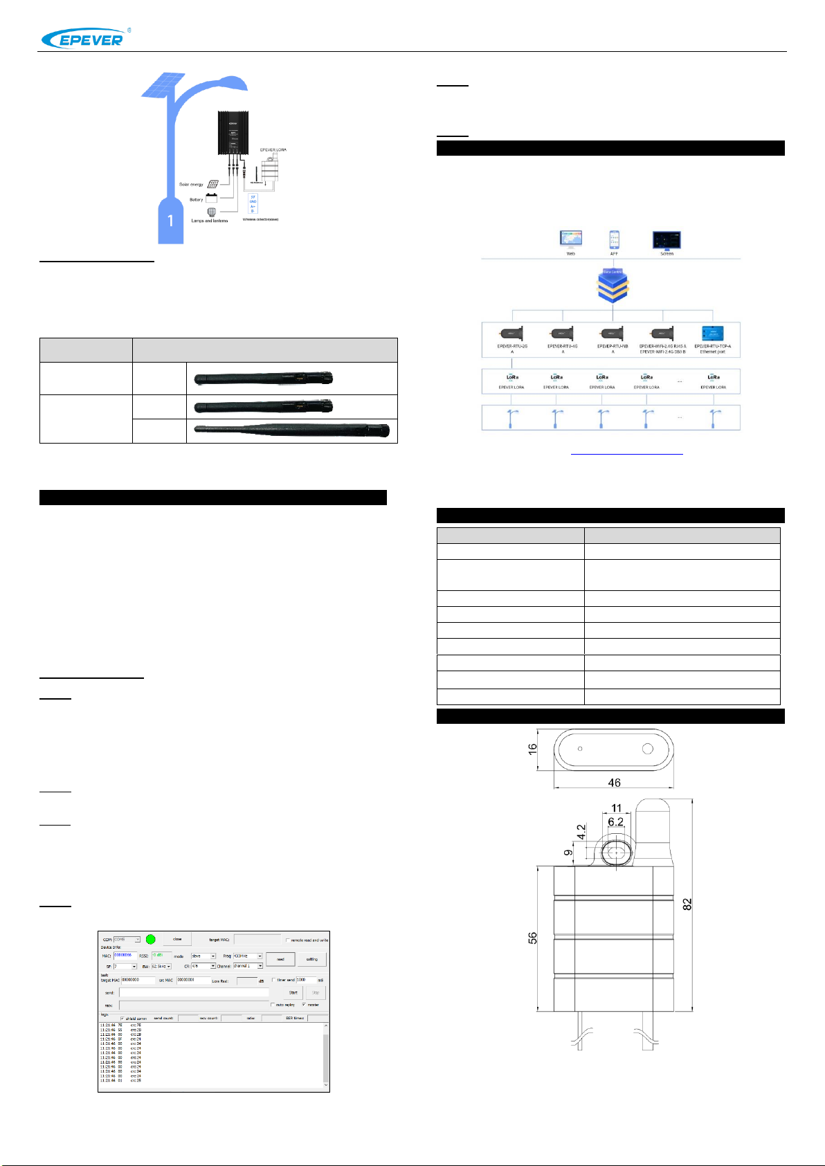
3. Appearance
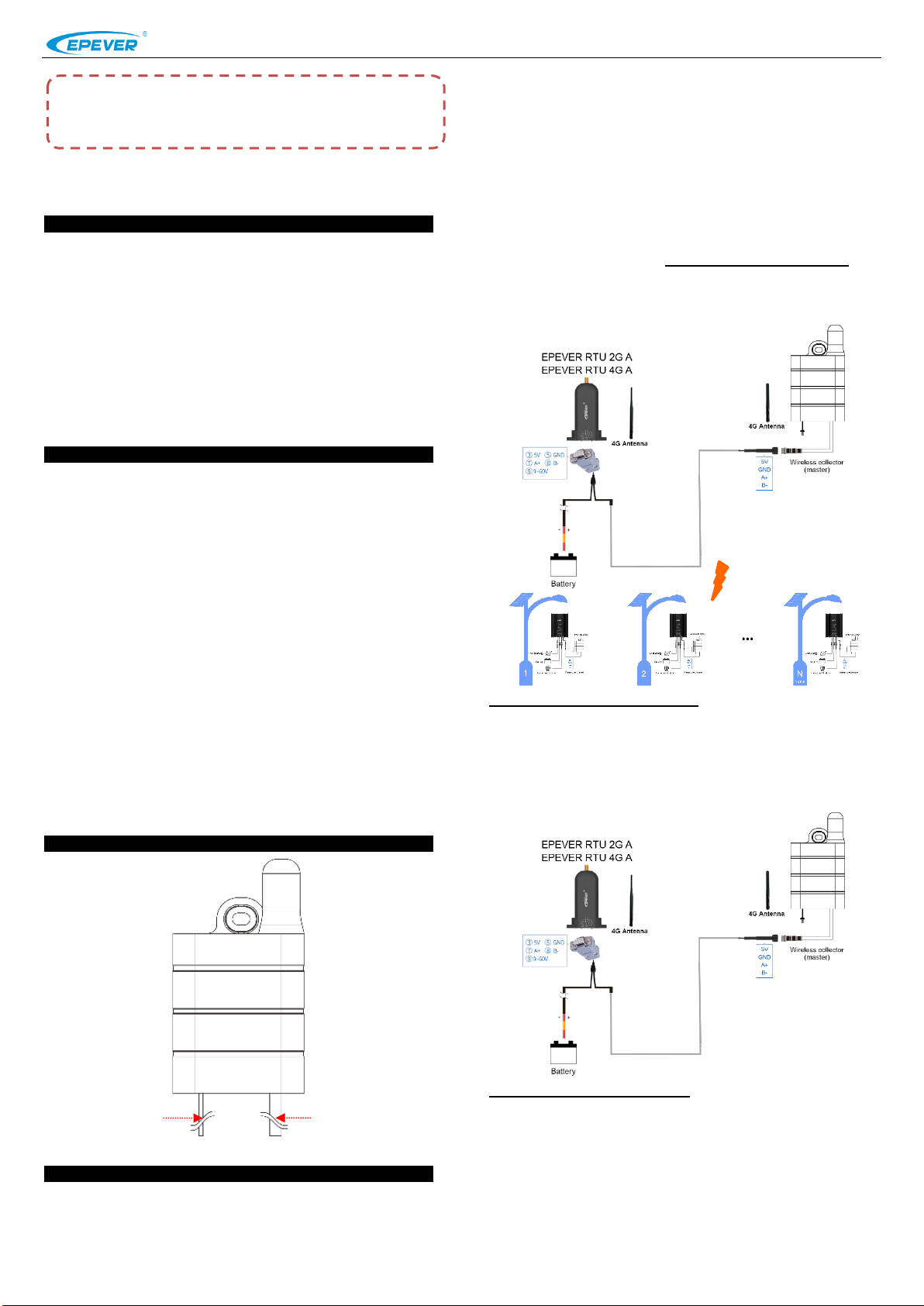
4. System Connection
The EPEVER LORA shall be used to match the cloud monitoring platform,
concentrator, and solar controller. To control multiple street lights over a
longer distance, you can connect a concentrator and multiple EPEVER
LORA devices in the "one-to-more" connection diagram below. The EPEVER
LORA will collect all system data to upload to the server.
Notes:
1. In the "one to more" connection diagram, it is necessary to set one LORA as
the master device and the remaining LORAs as the slave devices. The master-
slave mode setting refers to chapter 5, Configure EPEVER LORA (Optional).
2. The master LORA can connect 100 sets slave LORA at most, and the longest
wireless transmission distance up to 2.3 km.
Step1 Connect master EPEVER LORA
In the "one to more" connection diagram, one LORA will be set as the
master device. Through the Y-type LLT M12-4 cable, it will be connected to
the concentrator directly. The other end of the Y-type LLT M12-4 cable will
be connected with a battery to provide power.
Step2 Connect slave EPEVER LORA
In the "one to more" connection diagram, the slave LORA is connected to
the solar controller through the RS485 com. Cable directly. It shows as the
following figure.
※Thanks for selecting the EPEVER LORA solar wireless collector. Please
read this manual carefully before using the product.
※ Please keep this manual for future reference.
❶Antenna cable
❷RS485 com. cable
HUIZHOU EPEVER TECHNOLOGY CO., LTD TEL: +86-10-82894896/82894112/+86-752-3889706 Website: www.epever.com
34
Step3 Connect antenna
The antenna connector of the EPEVER LORA adopts a 4G glue stick
antenna, which varies with the working frequency. An external antenna
complied with the working frequency is irreplaceable; other mismatched
antennas will affect product performance and damage the product severely.
Working
Frequency
Applicable Antenna
LORA
433/470MHZ
Include
LORA
868/915MHZ
Include
Optional
Caution: As a wireless terminal, keep the antenna away from the human body as
far as possible during the operation process.
5. Configure EPEVER LORA (Optional)
In the "one to more" connection diagram, one LORA needs to be set as the
master mode, and the remaining devices are in slave mode. The frequency
and channel of the slave devices must be consistent with the master device.
Note: The master-slave mode of the EPEVER LORA has been configured at the
factory. Users can quickly distinguish the master and slave devices according to
the master-slave device number provided in the configuration table (shipped with
the EPEVER LORA). This chapter generally does not need to be performed.
Suppose the user needs to change the parameters of the master device and slave
devices. In that case, you can configure them according to the following process.
Configuring process:
Step1: First, transform the communication port of the EPEVER LORA into
the USB port by LLT M12-4 cable, USB adapter, and then connect the USB
port to the PC.
Note: The LLT M12-4 cable and USB adapter are optional accessories. Please
contact the sales in advance for customizing.
Step2: Click to open the EPEVER LORA tools in the PC and connect
EPEVER LORA successfully.
Step3: Click the "Read" button to display the EPEVER LORA's parameters.
Note: The EPEVER LORA tool is a special configuration tool, which is convenient
to configure the parameters of terminals. Customers can apply for it from our
business or technical personnel after purchasing our products.
Step4: Click the "mode" drop-down box and select the "master" to set the
current EPEVER LORA to the master mode (the factory default mode).
Step5: Click the "mode" drop-down box and select the "slave" to set other
LORAs to the slave mode (Note: The frequency and channel of the slave device
must be consistent with the master device).
Step6: Finish the master-slave mode setting.
6. Applications
In the "one to more" connection diagram, one EPEVER concentrator
matched with several LORAs can connect the solar controller flexibly. The
user can remotely control the devices through the cloud platform and monitor
the real-time status.
Login into the cloud platform (https://iot.epsolarpv.com), remotely monitor the
real-time condition, or set the parameters.
Note: For new accounts, devices need to be manually added in the EPEVER cloud
before monitoring.
7. Specifications
Item
Specifications
Working Frequency
433 MHz/470 MHz /868 MHz /915 MHz
Communication channel
Upstream: Sub-1GHz
Downstream: RS485
Antenna connector
50Ω IPX connector
Communication Distance
≤2300m
Power
5VDC
Average power consumption
≤0.3W
Data transformer protocol
Special EPEVER transmission protocol
Environment temperature
-20℃~70℃
Guarantee period
two-year
8. Dimension
Any changes without prior notice! Version number: 3.0
This manual suits for next models
1
Other Epever Solar Panel manuals


