EpiSensor ZHM-20 User manual

User Guide
Wireless M-Bus Interface
Applies to: ZHM-20, ZHM-21
EPI-085-00
© EpiSensor

Table of Contents
Safety Information 4
Electrical Installation 4
Intended Use 6
Related Documents 6
Introduction 6
M-Bus Communications 6
Configuration 7
Scanning 7
Preset Settings 7
Valid Baud Rates 7
Connection 7
Reading Data 7
Valve Control 8
User Interface 9
Status LED 10
Alt LED 11
Mode Button 11
Install Mode 11
Electrical Installation 12
Mechanical 13
Enclosure & Label Material 13
Mounting Instructions 13
Opening the Enclosure 13
Tamper Evident Seals 14
Compliance 14
Wireless Communications 15
Page 2
of 18


Safety Information
Please read these instructions carefully before trying to install, operate, service or maintain the ZHM. The
following special notes may appear throughout the user guide (or on the equipment labels) to warn of potential
hazards or to call attention information that clarifies or simplifies a procedure for users.
Symbol
Description
The addition of either symbol to a “Danger” or “Warning” safety label indicates that an
electrical hazard exists which will result in personal injury if the instructions are not
followed.
This is the safety alert symbol. It is used to alert you to potential personal injury hazards.
Obey all safety messages that follow this symbol to avoid possible injury or death.
Electrical Installation
Electrical equipment should be installed, operated, serviced and maintained only by qualified personnel. No
responsibility is assumed by EpiSensor for any consequences arising out of the use of this material.
A qualified person is one who has skills and knowledge related to the construction, installation, and operation of
electrical equipment and has received safety training to recognize and avoid the hazards involved.
Installation, wiring, testing and service must be performed in accordance with all local and national electrical
codes.
HAZARD OF ELECTRIC SHOCK, EXPLOSION, OR ARC FLASH
➔NEVER work alone.
➔Use appropriate personal protective equipment (PPE) and follow safe electrical work practices.
➔Only qualified electrical workers should install this equipment. Such work should be performed only
after reading the entire set of installation instructions.
➔If the equipment is not used in a manner specified by EpiSensor, the protection provided by the
equipment may be impaired.
Page 4
of 18

➔Before performing visual inspections, tests, or maintenance on this equipment, disconnect all sources
of electric power. Assume that all circuits are live until they have been completely de-energized,
tested, and tagged. Pay particular attention to the design of the power system. Consider all sources of
power, including the possibility of backfeeding.
➔Turn off all power supplying the ZHM and the area in which it is installed before working on it.
➔Always use a properly rated voltage sensing device to confirm that all power is off.
➔Before closing all covers and doors, inspect the work area for tools and objects that may have been
left inside the equipment or panel.
➔When removing or installing metering or other equipment, do not allow it to extend into an energised
bus.
➔The successful operation of this equipment depends upon proper handling,
➔Neglecting fundamental installation requirements may lead to personal injury as well as damage to
electrical equipment or other property.
➔Before performing Dielectric (Hi-Pot) or Megger testing on any equipment in which the energy meter
is installed, disconnect all input and output wires to the ZHM.
➔High voltage testing may damage electronic components contained in the ZHM.
➔Failure to follow these instructions will result in death or serious injury.
Installation & Safety Notes
➔EpiSensor equipment should be installed, operated, serviced and maintained only by qualified
personnel. EpiSensor does not assume any responsibility for any consequences arising out of the use
of this equipment.
➔Fuse for neutral terminal is required if the source neutral connection is not grounded.
➔Clearly label the device’s disconnect circuit mechanism and install it within easy reach of the operator.
➔The fuses / circuit breakers must be rated for the installation voltage and sized for the available fault
current.
➔The ZHM should be installed in a well ventilated location
Page 5
of 18

Intended Use
Do not use this device for critical control or protection applications where human or equipment safety relies on
the operation of the control circuit. Failure to follow these instructions can result in death, serious injury, or
equipment damage.
Related Documents
Related installation and configuration documents are listed in the following table:
Document
Reference No.
EpiSensor ZHM Datasheet
EPI-066-00
Install Sheet for ZHM-21
EPI-086-00
Install Sheet for ZHM-20
EPI-087-00
Gateway API User Guide
ESE-009-08
Introduction
EpiSensor’s ZHM Wireless M-Bus Interface is designed to make it easy to collect data from a wide range of
heating, cooling and other energy meters using the M-Bus wired communications standard. The ZHM-21 also
includes a relay output that can control a valve, allowing remote shut-off via the API on the EpiSensor Gateway.
The ZHM reports report data through the wireless sensor network to the Gateway, which then manages
bi-directional communications to various compatible software and IoT platforms.
M-Bus Communications
For a full description of the M-Bus specification please see http://www.m-bus.com/. Some specific details that
pertain to the ZHM devices are included here.
The ZHM-2x can be configured to either scan for Slave devices or communicate with a particular device (ZHM-21
only). The ZHM devices will then communicate with one Slave only on the M-Bus network. Depending on how
the ZHM is configured, this will be either the first Slave that the ZHM finds through the scan procedure, or the
device that it has been configured for.
Page 6
of 18

Configuration
Scanning
The ZHM-2x node scans for devices at Baud Rate 2400 starting at address 1 and proceeding to address 250. If
none are found, it tries all addresses again at Baud 9600 and finally Baud 300. The process restarts and
continues until a slave device is found.
Preset Settings
The ZHM-21 can be pre-configured through the Gateway if either the Baud or Address of the M-Bus device are
known. If one parameter is provided, the other will be scanned - so if a Baud Rate is provided, the 250 addresses
will be scanned at that baud rate only, or if the address is provided it will be scanned across baud rates 2400,
9600 and 300. When both are provided, no scanning is done.
Valid Baud Rates
When preconfiguring the settings on the ZHM-21, the following Baud Rates can be configured; 300, 600, 1200,
2400, 4800 and 9600. Of these, only 300, 2400 and 9600 are listed as recommended.
PARITY is always EVEN and STOP BITS are always 1 for M-Bus communication.
Connection
The connection to the M-Bus slave is done using a 2-core cable. The bus interfaces of the slaves are polarity
independent: that is, the two bus lines can be interchanged without affecting the operation of the slaves.
Besides protection aspects, this also results in simplified installation of the bus system.
Reading Data
The ZHM requests data from the Slave device using the M-Bus REQ_UD2 (Request for Class 2 Data). When the
RSP_UD (Data Transfer from Slave to Master after Request) has been received is it parsed by the ZHM which
then maps particular M-Bus “Value Information Fields” to EpiSensor Sensor IDs. It also converts from value
specific data types to EpiSensor data types.
The mapping is as follows;
M-Bus VIF
Description
Sensor ID
Description
E000 0nnn
Energy, 10(nnn-3) Wh, 0.001Wh to 10000Wh
370
Energy (KWH)
E010 1nnn
Power, 10(nnn-3) W, 0.001W to 10000W
376
Power (W)
E011 1nnn
Volume Flow, 10(nnn-6) m3/h, 0.001l/h to
10000l/h
377
Volume Flow (Litres per Hour)
E101 10nn
Flow Temperature, 10(nn-3)oC, 0.001oC to 1oC
371
Heat Celsius Out (C)
E101 11nn
Return Temperature, 10(nn-3) oC, 0.001oC to 1oC
372
Heat Celsius In (C)
Page 7
of 18
E110 00nn
Temperature Difference, 10(nn-3) K, 1mK to
1000mK
373
Heat Delta T (Kelvin)
E001 0nnn
Volume, 10(nnn-6) m3, 0.001l to 10000l
374
Volume 1 (litres)
E110 1110
Units for H.C.A. - dimensionless
375
Volume 2
Delta T (Kelvin) is not available from some manufacturers (e.g. Sontex) and is calculated as “Heat Delta T = Heat
Out - Heat In”. Volume 2 is also not available from some manufacturers (e.g. Sontex, Sensus or Kamstrup) and is
ignored.
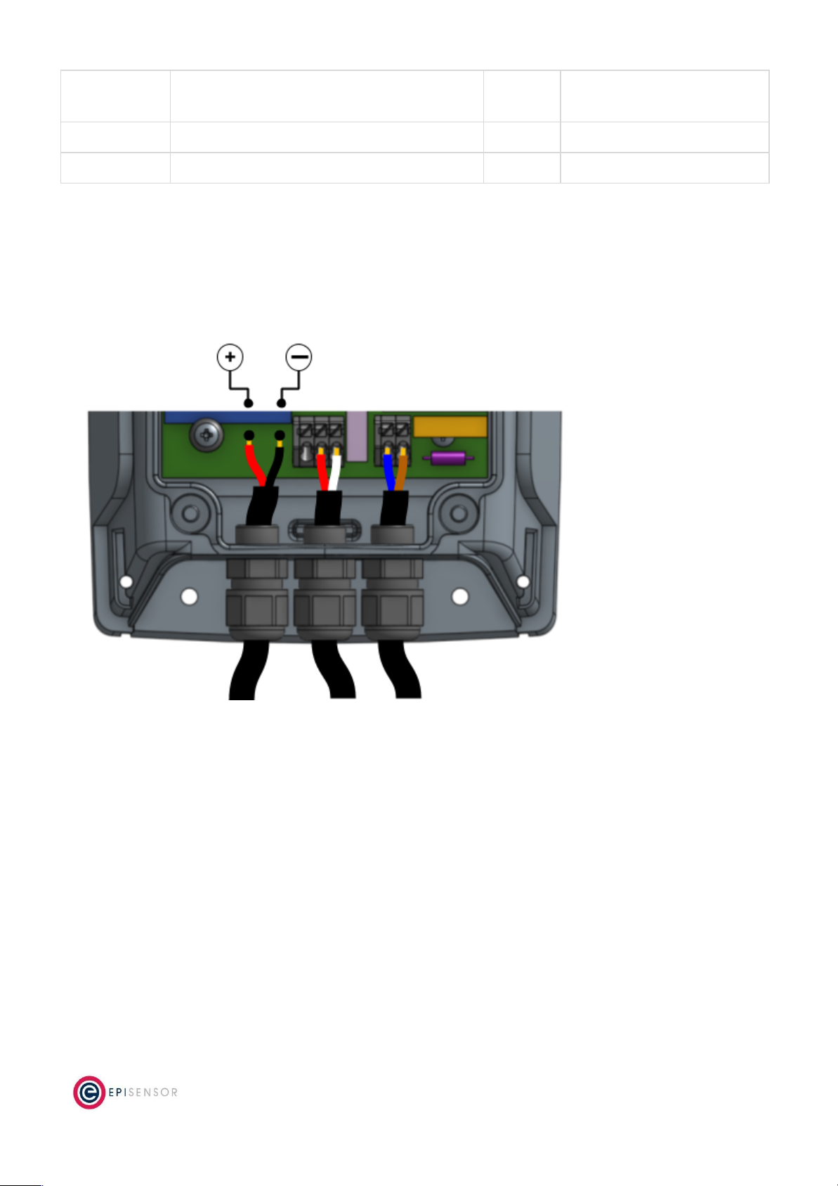
The M-Bus communications terminals and polarity are shown on the following diagram:
Valve Control
This section of the document has information on the switching capability of the ZHM-21. The relay on the
ZHM-21 can be controlled remotely with a command sent from the Gateway’s web interface, or by sending an
API request to the Gateway.
Connecting a Valve to the Relay
There is a single-channel relay output available on the ZHM-21. This output is designed for remotely controlling
a cut-off valve, and is not intended for switching large electrical loads. The location of the valve control
terminals are shown on the diagram below.
Page 8
of 18

The switching capability of the ZHM relay is 0.1A at 250V (~ 25 Watts). There is one ‘normally open’ and one
‘normally closed’ connection option. For additional technical information on the relays, like rated voltages,
currents, and type - please check the ZHM datasheet.
User Interface
There are two LED’s and one button on the front panel of the ZHM product range that are used to show the
status of the product and to issue commands. This section describes how to interact with user interface and
what each state means.
Page 9
of 18
A node must be in “command mode” before users can interact with the product. To put the node in Command
Mode, press and hold the “MODE” button for 2 seconds, then release. At this point, a battery powered node will
switch the LED On Solid, while a mains powered node will flicker the LED and then switch the LED On Solid.
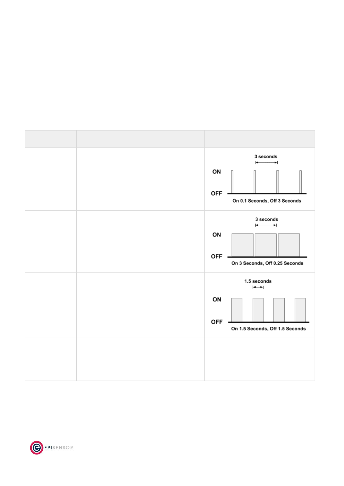
Status LED
The red status LED will flash in different sequences depending on the current state of the ZHM. This table below
lists all possible LED flash sequences and their meaning.
Flash Sequence
Description
Diagram
Heartbeat
The node is operating correctly and has
successfully joined a wireless network.
Inverse Heartbeat
The node is has received valid security keys, but
is not connected to a Gateway.
Square Wave
The node is operating correctly but has lost
contact with the Gateway.
On Solid, or Off
If the LED is On Solid, the node is searching for a
Gateway to join. If it is Off, the node may not be
powered, or there is a problem with the node.
Check the power supply, and if the problem
persists, contact EpiSensor support.
Page 10
of 18

Alt LED
The Alt LED will flash when data is transmitted or received on the ZigBee wireless network. For mains powered
nodes, it will always be active - but for battery powered nodes, it will only be active when in Command Mode.
Mode Button
The following options are available with Command Mode. The button should be pressed and then released to
register a valid button press. If no further button presses are made, the device will terminate “command mode”
4 seconds after the last button press.
Press
Description
0
Send a PING message disable any active Install Mode or Range Test Mode. If the node is not joined,
try and join a network.
1
Send a DATA message to the Gateway for any enabled sensors that are not reporting in
‘snap-to-clock’ mode.
2
Leave the current network. Mains powered Nodes will automatically try and join a new network
once they have left and will periodically retry the join. Battery powered nodes will go to sleep.
4
Start “Install Mode”. Node sends a PING message every 15 seconds, with the LED pulse speed
indicating the wireless signal strength of the reply. Automatically expires after 5 minutes.
6
Reboot the node. Security keys for the wireless network the node is joined to will not be erased, and
all other settings will remain the same.
8
Factory-reset the node and perform a reboot. All settings and security keys will be lost. The node
will be returned to its factory default state.
12
Start “Range Test” mode. Node will send a PING message every 5 seconds. The LED pulse speed
indicates the wireless signal strength of the reply. Automatically expires after 5 minutes.
Install Mode
Issuing a press sequence on the Mode button of a powered node can enable either “Install Mode” or “Site
Survey Mode” on that node. In this mode, the LED will flash at a rate that indicates the wireless signal strength
(Link Quality Indicator) of that node, based on the following table:
Flash Rate
Flashes per Second
Wireless Signal Strength
LQI
Very Fast
10 flashes / second (Light on 50ms, off 50ms)
Very good Signal
> 200
Fast
2 flashes / second (LED on 250ms, off 250ms)
Good Signal
> 150
Slow
1 flash / 2 seconds (LED on 1 sec, off 1 sec)
OK Signal
> 100
Very Slow
1 flash / 6 seconds (LED on 3 sec, off 3 sec)
Poor Signal
< 100
Page 11
of 18

This mode expires after 15 minutes for Install Mode and 5 minutes for Site Survey Mode.
Electrical Installation
The ZHM is a mains powered device. The mains cable is colour coded to conform to European CENELEC
standards. The CENELEC standard insulation colours are as follows:
Live – Brown
N – Blue
Important Note: The ZHM should be connected via a switched junction box and breaker to protect the cable.
Also, please ensure that the live connection is made on the same circuit as the neutral connection where
residual-current devices (RCD’s) are used.
Installation should only be carried out only by personnel qualified in the installation of electrical equipment. All
parts of the circuit within the enclosure must be considered to be at dangerously high mains voltage when the
unit is connected to a mains voltage source.
Page 12
of 18

Mechanical
This section describes how to wall-mount the ZHM enclosure, the enclosure materials and important safety
considerations when connecting the ZHM to external systems.
Enclosure & Label Material
The ZHM is housed in an IP67 water and dust proof enclosure to provide maximum safety, flexibility and
reliability. The enclosure material is polycarbonate plastic, which is resistant to a variety of chemicals, oils and
detergents.
The front label is made from polycarbonate. There will be two or more labels on the back of the enclosure,
depending on the model selected. The compliance label is made from PVC and the serial number label is made
from polyethylene film.
Mounting Instructions
The ZHM product range will have two (ZHM-20) or three (ZHM-21) cable glands at the bottom depending on the
model.
The ZHM requires 2 screws for mounting. These screws can be preinstalled on a vertical surface spaced 122mm
vertically apart. The head of the screw should be less than 8.5mm in diameter and the screw thickness should be
less than 4.5mm. The screws should be left unscrewed by more than 5 mm before installing the enclosure.
Important Safety Note
The enclosure of the ZHM must not be drilled, cut or modified in any way for mounting or
connecting to external systems.
All parts of the circuit within the enclosure must be considered to be at dangerously high
mains voltage when the unit is connected to a mains voltage source. Modifying the
enclosure could expose parts of the system to users, or cause an internal fault or short
circuit.
There are no user-serviceable parts inside the ZHM enclosure, and it should always be
isolated from mains voltages before opening the enclosure lid.
Opening the Enclosure
To make connections to the ZHM, it is necessary to open the lid of the enclosure. This is fastened with four
screws that are accessible from the back of the enclosure. This should only be done by qualified personnel, and
Page 13
of 18
only when the ZHM has been isolated from any high voltage supplies. Please consult the safety notes at the start
of this user guide for more information.
Important Safety Note
EpiSensor equipment should be installed, operated, serviced and maintained only by
qualified personnel.
There are no user-serviceable parts inside the ZHM enclosure, and it should always be
isolated from mains voltages before opening the enclosure lid.
When closing the lid, take care to ensure that no wires or cable ties are obstructing the gasket of the enclosure,
as this could interfere with the waterproof seal. When tightening the screws on the lid, apply pressure to the
enclosure so the gasket is compressed, and tighten each screw gradually and in sequence.
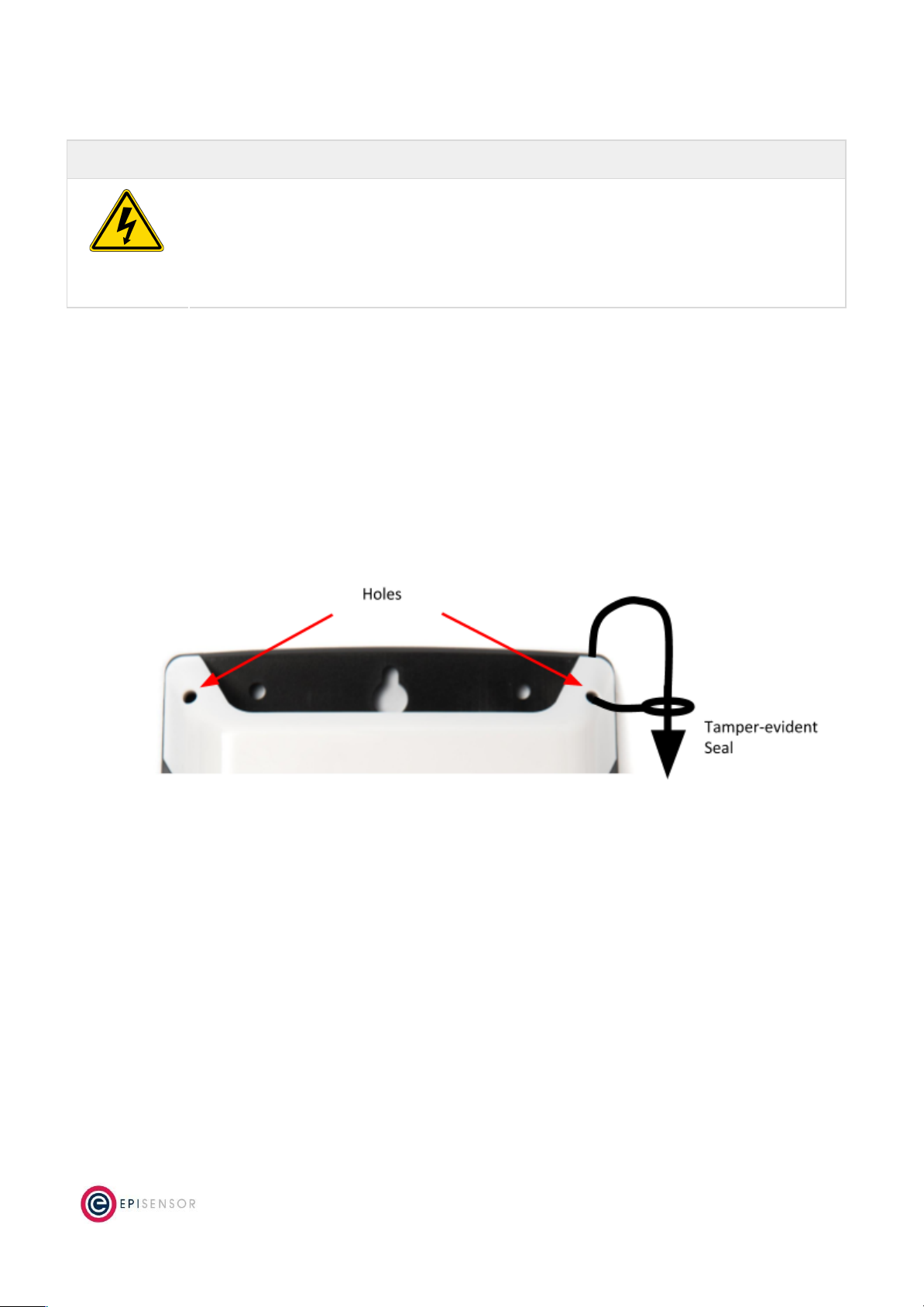
Tamper Evident Seals
Some applications (particularly applications where data is used for billing purposes) will require a tamper
evident seals to be attached to the ZHM enclosure. These seals can be attached to two or more of the corners of
the ZHM enclosure, as shown on the diagram below.
Compliance
There is a compliance label on the back of the ZHM enclosure that has important regulatory and node
identification information.
The label material is gloss white PVC foil with permanent adhesive and gloss overlaminate. The following table
lists the certification and safety symbols that appear on the certification labels of EpiSensor products. Please
refer to it for a definition of each symbol.
Page 14
of 18

Symbol
Name
Description
CE Mark
This marking certifies that a product has met EU consumer safety,
health or environmental requirements.
WEEE Symbol
The directive imposes the responsibility for the disposal of waste
electrical and electronic equipment on the manufacturers of such
equipment.
Class II IEC
Protection
This certifies that this product has been designed in such a way that it
does not require a safety connection to electrical earth/ground.
IP / NEMA Rating
Water and dust ingress protection standard. IP67 / NEMA 4 means
complete protection against contact with dust, and protected from
ingress of water when immersed in up to 1 metre depth for up to 30
minutes. For more information, see IEC 60529.
RoHS Directive
Restriction of Hazardous Substances Directive restricts (with
exceptions) the use of six hazardous materials in the manufacture of
various types of electronic and electrical equipment.
Safety Alert
This is the safety alert symbol. It is used to alert you to potential
personal injury hazards. Obey all safety messages that follow this
symbol to avoid possible injury or death.
Danger / Warning
The addition of either symbol to a “Danger” or “Warning” safety label
indicates that an electrical hazard exists which will result in personal
injury if the instructions are not followed.
EpiSensor products are not suitable or specifically designed, manufactured or licensed for use in military,
aviation, powerplant, medical or in other inherently dangerous or safety critical applications.
Wireless Communications
All EpiSensor products use IEEE 802.15.4 ZigBee Pro for wireless communications operating at 2.4GHz. This is a
secure, scalable mesh networking communications protocol designed for transmitting small amounts of data
reliably, and at low power levels.
There are two types of nodes in the EpiSensor wireless mesh network: powered nodes and battery nodes.
Powered nodes on the wireless sensor network are capable of routing data from any other type of wireless
nodes.
Page 15
of 18

Range extenders are powered nodes where the main function is to route data. Any node with a mains power
supply will act as a routing node in the network. Battery nodes do not route data – they spend most of the time
in a low power mode.
Each powered node can have up to 32 ‘neighbours’ which are nodes with a mains power supply and can Route
data back to the Gateway. They can also have up to 32 ‘children’ which are nodes that are battery powered and
cannot participate in any routing in the network.
The range that can be achieved with ZigBee will depend mainly on two factors: the power level of the ZigBee
radio module and the environment that the device is installed in. There are two types of ZigBee radio module
used across the EpiSensor product range, a power amplified version, and non-power amplified version.
The power output of nodes with a power-amplified module can be configured with an output power level of +20
dBm depending on the region they are deployed in. Non-power amplified nodes have a maximum output power
of +8 dBm.
Module Type
Tx Power
Rx Sensitivity
LoS Range
Region(s)
Normal
+8 dBm
-101dBm
up to 300m (985ft)
Worldwide
Power-amplified
+20 dBm
-106dBm
up to 1600m (5250ft)
North America (FCC / IC)
All communications over the ZigBee wireless network is AES 128-bit encrypted. For more detailed information
on ZigBee security features, contact EpiSensor support.
Sensors
The following is a list of all sensors available on the ZHM. The reporting mode, reporting interval and logging
enabled columns refer to the factory default settings, these settings can be configured from the Gateway.
Page 16
of 18
Sensor ID
Name
Description
Reporting
Mode
Reporting
Interval
Logging
Enabled
359
Switch
Switch Status, 1 = On, 0 = Off (ZHM-21 only)
Delta and
Interval
240
Yes
370
Energy (KWH)
Energy as displayed on M-Bus Meter
Snap to Clock
15
Yes
371
Heat Out
Heat Out as displayed on the Heat meter
Snap to Clock
15
Yes
372
Heat In
Heat In as displayed on the Heat meter
Snap to Clock
15
Yes
373
Delta T
Heat Difference calculated on the Heat meter
Snap to Clock
15
Yes
374
Volume1
Volume Register from the Heat Meter
Snap to Clock
15
Yes
375
Volume2
HCA register from the Heat meter
Snap to Clock
15
Yes
376
Power
Power Register from the Heat Meter
Snap to Clock
15
Yes
377
Volume Flow
Volume Flow Register from the Heat Meter
Snap to Clock
15
Yes
Ordering Information
EpiSensor products are available to order directly or via EpiSensor’s distribution partners. The following table
lists the available ZHM options.
SKU
Description
ZHM-20
Mains powered, M-Bus master, max 1 connected meter
ZHM-21
Mains powered, M-Bus master, max 1 connected meter, with valve control
Troubleshooting & Support
If you are experiencing problems with your ZHM or any other part of your EpiSensor system, or you notice
something unusual - please contact EpiSensor support at the following email address, phone number or via live
chat on our website.
●Email: [email protected]
●Tel: +353 61 512 500
●Website: http://episensor.com
For customers and partners who are deploying systems in business-critical environments, there are a number of
support packages available that offer a higher level of service and response time. For more information on
EpiSensor Premium Support, visit: http://episensor.com/premium-support/
Page 17
of 18

Warranty
All EpiSensor products and provided with a 365 day limited warranty effective from the shipping/invoice date of
an order. During the warranty period, under the conditions of normal use, EpiSensor will repair or replace any
product that has a manufacturing defect.
Warranty can be extended by up to 4 years within 30 days of a purchase. For more information on warranty,
visit: http://episensor.com/warranty/
Glossary
Definitions for terms and abbreviations used in this document are listed in the following table:
Term
Description
Sensor
Describes a feed of data within the EpiSensor system
Node
Used to describe a physical EpiSensor product
Gateway
The central computer that managed the EpiSensor system
ZigBee
IEEE 802.15.4 Wireless communications standard that EpiSensor nodes use
WSN
Wireless Sensor Network
Reporting Mode
Defines how an EpiSensor node should report data to the Gateway
Reporting
Interval
The length of time between each data point produced by a node
Snap to Clock
Reporting mode where data is ‘snapped’ to the nearest 1 minute / 5 minute / 15 minute
interval etc.
Interval and
Delta
Reporting mode where data is produced when the reporting interval has elapsed, unless a
change is detected
Allow join mode
A mode that can be enabled on the Gateway that allows new wireless nodes to join
Page 18
of 18
This manual suits for next models
1
Table of contents
Other EpiSensor Recording Equipment manuals


Popular Recording Equipment manuals by other brands


Subzero
Subzero BASE-2 user manual

Pololu
Pololu Zumo Shield For Arduino user guide

Lexicon
Lexicon PCM 80 - REV 1 Quick reference guide

Panasonic
Panasonic SV-3800 operating instructions

Northern Airborne Technology
Northern Airborne Technology AA224 series Installation and operation manual

Lange
Lange BUHLER 1027 Short manual