EpiSensor ZMB-30 User manual
User Guide
Wireless Modbus Interface
Applies to: ZMB-30, ZMB-31, ZMB-33
EPI-194-00
© EpiSensor

Table of Contents
Safety Information 3
Electrical Installation 3
Intended Use 5
Related Documents 5
Introduction 6
User Interface 6
Status LED 6
Alt LED 7
Mode Button 7
Install Mode 8
Electrical Installation 8
Mechanical 9
Enclosure & Label Material 9
Mounting Instructions 9
Opening the Enclosure 10
Tamper Evident Seals 10
Compliance 11
Communications 12
Configuration 13
Wireless Communications 15
Sensors 16
Reading Data 16
Ordering Information 17
Troubleshooting & Support 17
Warranty 17
Glossary 17
Page 2of 19

Safety Information
Please read these instructions carefully before trying to install, operate, service or maintain the ZMB. The
following special notes may appear throughout the user guide (or on the equipment labels) to warn of potential
hazards or to call attention to information that clarifies or simplifies a procedure for users.
Symbol
Description
The addition of either symbol to a “Danger” or “Warning” safety label indicates that an
electrical hazard exists which will result in personal injury if the instructions are not
followed.
This is the safety alert symbol. It is used to alert you to potential personal injury hazards.
Obey all safety messages that follow this symbol to avoid possible injury or death.
Electrical Installation
Electrical equipment should be installed, operated, serviced and maintained only by qualified personnel. No
responsibility is assumed by EpiSensor for any consequences arising out of the use of this material.
A qualified person is one who has skills and knowledge related to the construction, installation, and operation of
electrical equipment and has received safety training to recognize and avoid the hazards involved.
Installation, wiring, testing and service must be performed in accordance with all local and national electrical
codes.
HAZARD OF ELECTRIC SHOCK, EXPLOSION, OR ARC FLASH
➔NEVER work alone.
➔Use appropriate personal protective equipment (PPE) and follow safe electrical work practices.
➔Only qualified electrical workers should install this equipment. Such work should be performed only
after reading the entire set of installation instructions.
➔If the equipment is not used in a manner specified by EpiSensor, the protection provided by the
equipment may be impaired.
Page 3of 19

➔Before performing visual inspections, tests, or maintenance on this equipment, disconnect all sources
of electric power. Assume that all circuits are live until they have been completely de-energized,
tested, and tagged. Pay particular attention to the design of the power system. Consider all sources of
power, including the possibility of backfeeding.
➔Turn off all power supplying the ZMB and the area in which it is installed before working on it.
➔Always use a properly rated voltage sensing device to confirm that all power is off.
➔Before closing all covers and doors, inspect the work area for tools and objects that may have been
left inside the equipment or panel.
➔When removing or installing metering or other equipment, do not allow it to extend into an energised
bus.
➔The successful operation of this equipment depends upon proper handling,
➔Neglecting fundamental installation requirements may lead to personal injury as well as damage to
electrical equipment or other property.
➔Before performing Dielectric (Hi-Pot) or Megger testing on any equipment in which the energy meter
is installed, disconnect all input and output wires to the ZMB.
➔High voltage testing may damage electronic components contained in the ZMB.
➔Failure to follow these instructions will result in death or serious injury.
Installation & Safety Notes
➔EpiSensor equipment should be installed, operated, serviced and maintained only by qualified
personnel. EpiSensor does not assume any responsibility for any consequences arising out of the use
of this equipment.
➔Fuse for neutral terminal is required if the source neutral connection is not grounded.
➔Clearly label the device’s disconnect circuit mechanism and install it within easy reach of the operator.
➔The fuses / circuit breakers must be rated for the installation voltage and sized for the available fault
current.
➔The ZMB should be installed in a well ventilated location
Page 4of 19

Intended Use
Do not use this device for critical control or protection applications where human or equipment safety relies on
the operation of the control circuit. Failure to follow these instructions can result in death, serious injury, or
equipment damage.
Related Documents
Related installation and configuration documents are listed in the following table:
Document
Reference No.
EpiSensor ZMB Datasheet
EPI-195-00
Install Sheet for ZMB-3X
EPI-090-00
Application Note - ZMB Device Compatibility
EPI-143-00
Application Note - Modifying Node Profiles for ZMB Product Range
EPI-104-00
Gateway API User Guide
ESE-009-08
Page 5of 19
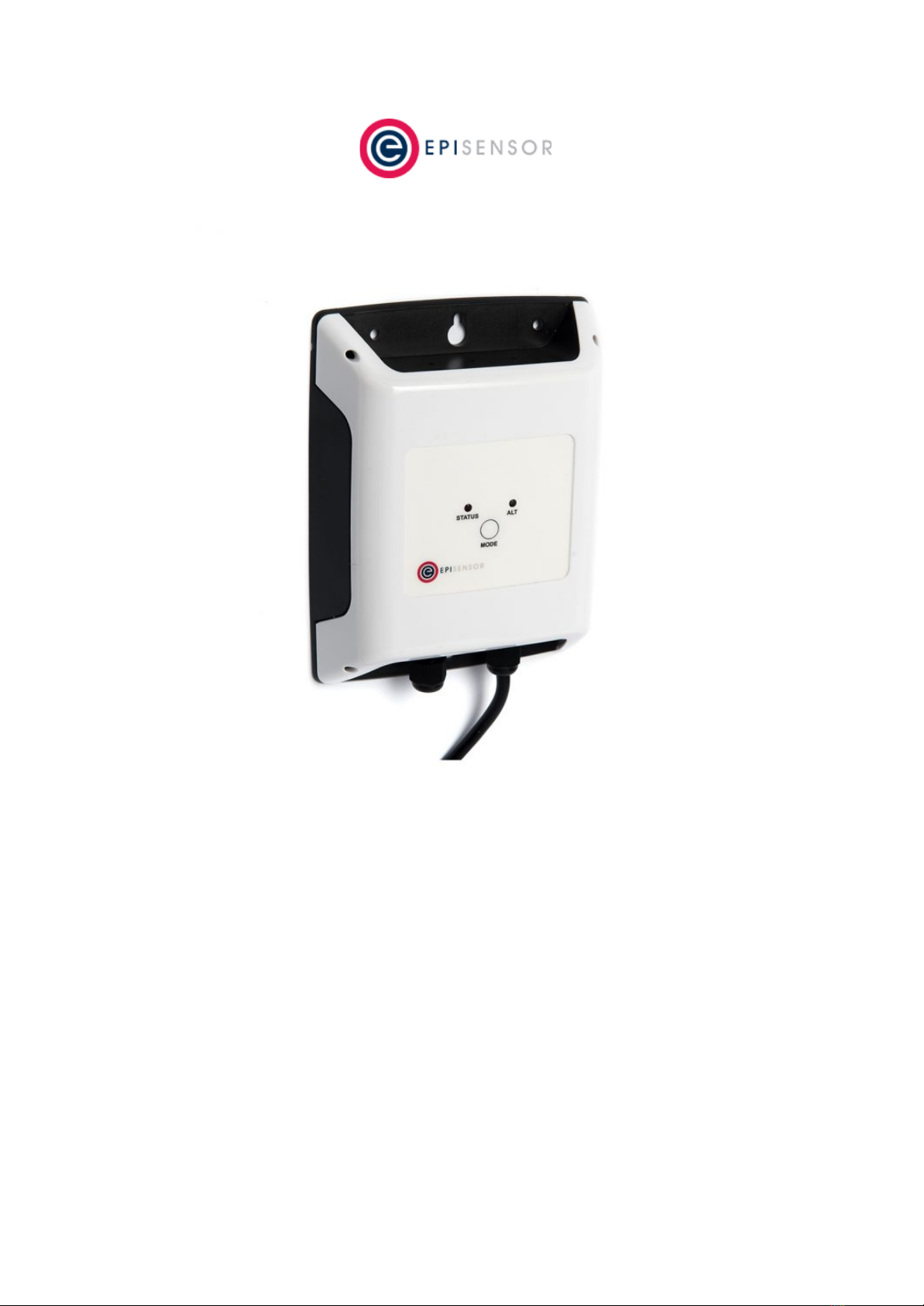
Introduction
EpiSensor’s ZMB Wireless Modbus Interface is designed to make it easy to collect data from a wide range of
heating, cooling and other energy meters using the Modbus RTU (over RS-485) wired communications standard.
The ZMB reports data through the wireless sensor network to the Gateway, which then manages bi-directional
communications to various compatible software and IoT platforms.
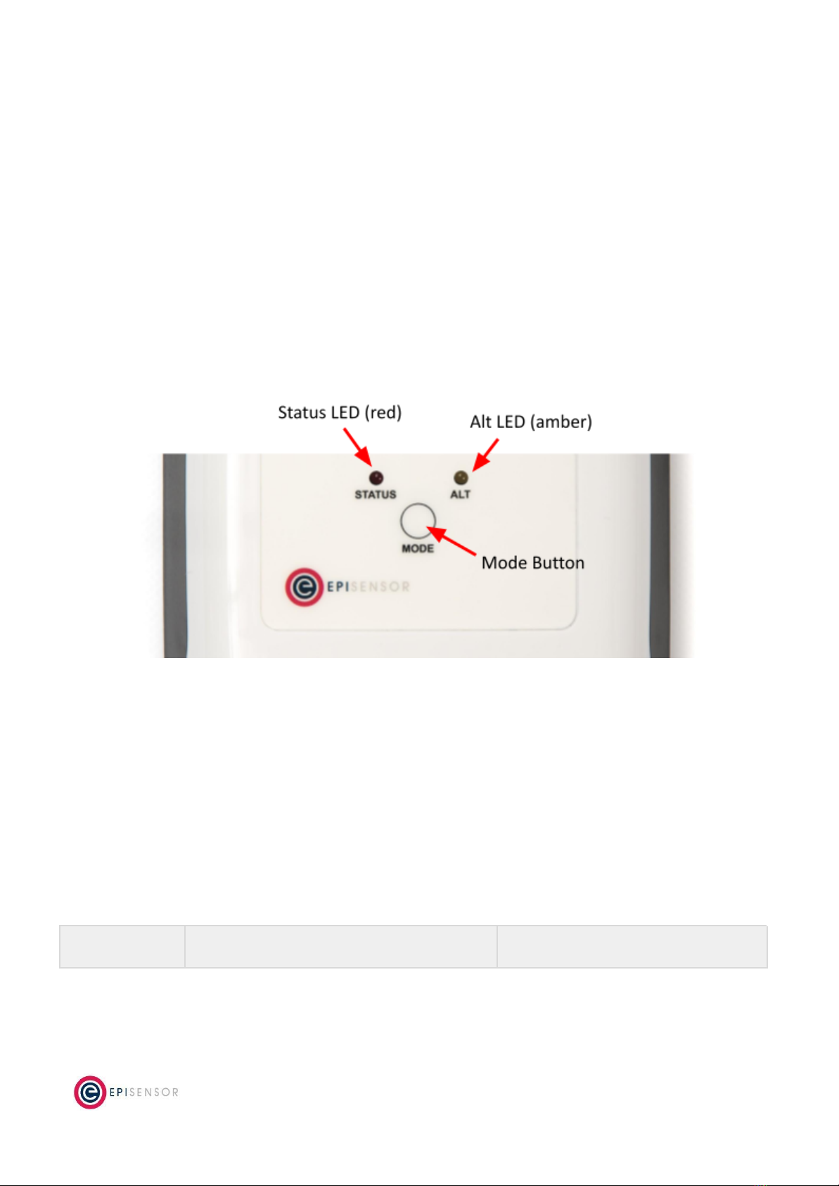
User Interface
There are two LED’s and one button on the front panel of the ZMB product range that are used to show the
status of the product and to issue commands. This section describes how to interact with user interface and
what each state means.
A node must be in “command mode” before users can interact with the product. To put the node in Command
Mode, press and hold the “MODE” button for 2 seconds, then release. At this point, a battery powered node will
switch the LED On Solid, while a mains powered node will flicker the LED and then switch the LED On Solid.
Status LED
The red status LED will flash in different sequences depending on the current state of the ZMB. This table below
lists all possible LED flash sequences and their meaning.
Flash Sequence
Description
Diagram
Page 6of 19

Heartbeat
The node is operating correctly and has
successfully joined a wireless network.
Inverse Heartbeat
The node is has received valid security keys, but
is not connected to a Gateway.
Square Wave
The node is operating correctly but has lost
contact with the Gateway.
On Solid, or Off
If the LED is On Solid, the node is searching for a
Gateway to join. If it is Off, the node may not be
powered, or there is a problem with the node.
Check the power supply, and if the problem
persists, contact EpiSensor support.
Alt LED
The Alt LED will flash when data is transmitted or received on the ZigBee wireless network. For mains powered
nodes, it will always be active - but for battery powered nodes, it will only be active when in Command Mode.
Mode Button
The following options are available with Command Mode. The button should be pressed and then released to
register a valid button press. If no further button presses are made, the device will terminate “command mode”
4 seconds after the last button press.
Press
Description
0
Send a PING message disable any active Install Mode or Range Test Mode. If the node is not joined,
try and join a network.
Page 7of 19

1
Send a DATA message to the Gateway for any enabled sensors that are not reporting in
‘snap-to-clock’ mode.
2
Leave the current network. Mains powered Nodes will automatically try and join a new network
once they have left and will periodically retry the join. Battery powered nodes will go to sleep.
4
Start “Install Mode”. Node sends a PING message every 15 seconds, with the LED pulse speed
indicating the wireless signal strength of the reply. Automatically expires after 5 minutes.
6
Reboot the node. Security keys for the wireless network the node is joined to will not be erased, and
all other settings will remain the same.
8
Factory-reset the node and perform a reboot. All settings and security keys will be lost. The node will
be returned to its factory default state.
12
Start “Range Test” mode. Node will send a PING message every 5 seconds. The LED pulse speed
indicates the wireless signal strength of the reply. Automatically expires after 5 minutes.
Install Mode
Issuing a press sequence on the Mode button of a powered node can enable either “Install Mode” or “Site
Survey Mode” on that node. In this mode, the LED will flash at a rate that indicates the wireless signal strength
(Link Quality Indicator) of that node, based on the following table:
Flash Rate
Flashes per Second
Wireless Signal Strength
LQI
Very Fast
10 flashes / second (Light on 50ms, off 50ms)
Very good Signal
> 200
Fast
2 flashes / second (LED on 250ms, off 250ms)
Good Signal
> 150
Slow
1 flash / 2 seconds (LED on 1 sec, off 1 sec)
OK Signal
> 100
Very Slow
1 flash / 6 seconds (LED on 3 sec, off 3 sec)
Poor Signal
< 100
This mode expires after 15 minutes for Install Mode and 5 minutes for Site Survey Mode.
Electrical Installation
The ZMB is a mains powered device. The mains cable is colour coded to conform to European CENELEC
standards. The CENELEC standard insulation colours are as follows:
Live – Brown
N – Blue
Important Note: The ZMB should be connected via a switched junction box and breaker to protect the cable.
Also, please ensure that the live connection is made on the same circuit as the neutral connection where
residual-current devices (RCD’s) are used.
Page 8of 19

Installation should only be carried out only by personnel qualified in the installation of electrical equipment. All
parts of the circuit within the enclosure must be considered to be at dangerously high mains voltage when the
unit is connected to a mains voltage source.
Mechanical
This section describes how to wall-mount the ZMB enclosure, the enclosure materials and important safety
considerations when connecting the ZMB to external systems.
Enclosure & Label Material
The ZMB is housed in an IP67 water and dust proof enclosure to provide maximum safety, flexibility and
reliability. The enclosure material is polycarbonate plastic, which is resistant to a variety of chemicals, oils and
detergents.
The front label is made from polycarbonate. There will be two or more labels on the back of the enclosure,
depending on the model selected. The compliance label is made from PVC and the serial number label is made
from polyethylene film.
Mounting Instructions
The ZMB product range will have two (ZMB-31, ZMB-33) or three (ZMB-21) cable glands at the bottom
depending on the model.
The ZMB requires 2 screws for mounting. These screws can be preinstalled on a vertical surface spaced 122mm
vertically apart. The head of the screw should be less than 8.5mm in diameter and the screw thickness should be
less than 4.5mm. The screws should be left unscrewed by more than 5 mm before installing the enclosure.
Important Safety Note
The enclosure of the ZMB must not be drilled, cut or modified in any way for mounting or
connecting to external systems.
All parts of the circuit within the enclosure must be considered to be at dangerously high
mains voltage when the unit is connected to a mains voltage source. Modifying the
enclosure could expose parts of the system to users, or cause an internal fault or short
circuit.
There are no user-serviceable parts inside the ZMB enclosure, and it should always be
isolated from mains voltages before opening the enclosure lid.
Page 9of 19
Opening the Enclosure
To make connections to the ZMB, it is necessary to open the lid of the enclosure. This is fastened with four
screws that are accessible from the back of the enclosure. This should only be done by qualified personnel, and
only when the ZMB has been isolated from any high voltage supplies. Please consult the safety notes at the start
of this user guide for more information.
Important Safety Note
EpiSensor equipment should be installed, operated, serviced and maintained only by
qualified personnel.
There are no user-serviceable parts inside the ZMB enclosure, and it should always be
isolated from mains voltages before opening the enclosure lid.
When closing the lid, take care to ensure that no wires or cable ties are obstructing the gasket of the enclosure,
as this could interfere with the waterproof seal. When tightening the screws on the lid, apply pressure to the
enclosure so the gasket is compressed, and tighten each screw gradually and in sequence.
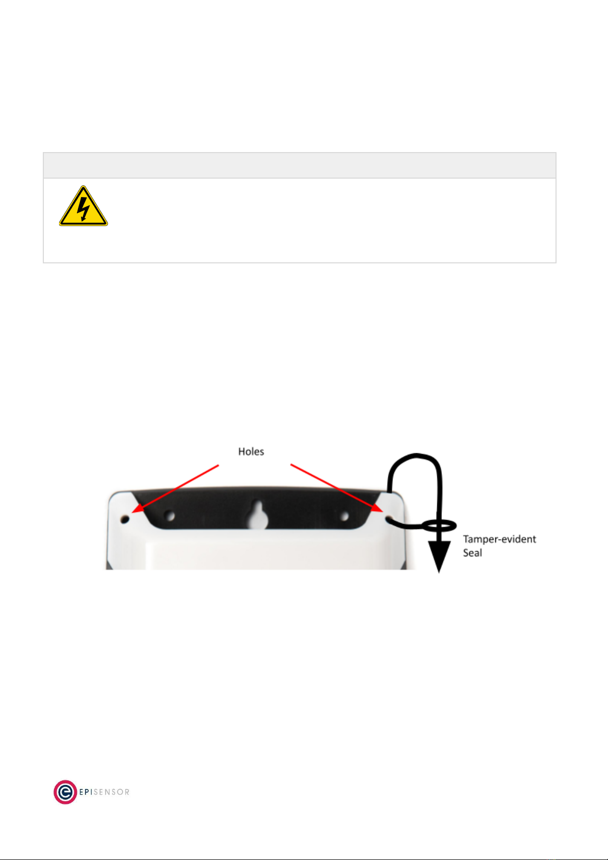
Tamper Evident Seals
Some applications (particularly applications where data is used for billing purposes) will require tamper evident
seals to be attached to the ZMB enclosure. These seals can be attached to two or more of the corners of the
ZMB enclosure, as shown on the diagram below.
Page 10 of 19
Compliance
There is a compliance label on the back of the ZMB enclosure that has important regulatory and node
identification information.
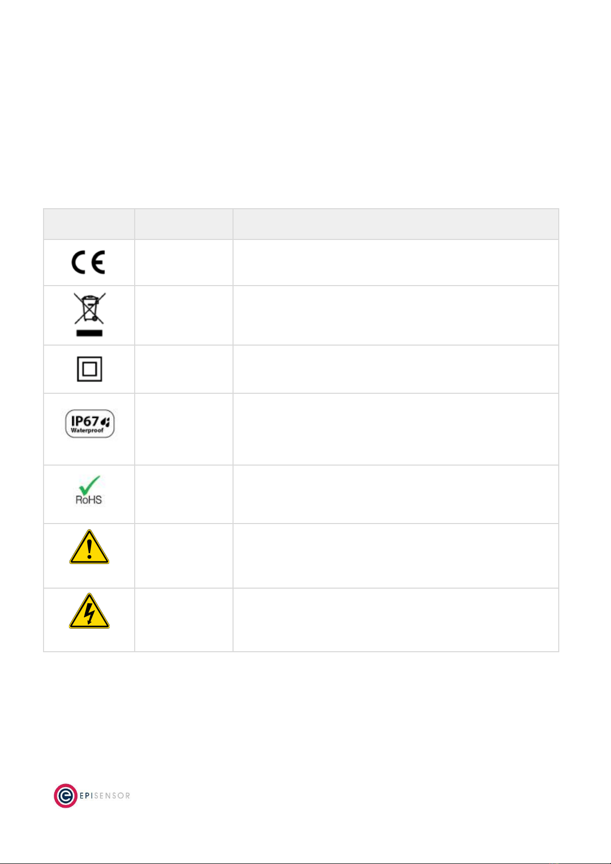
The label material is gloss white PVC foil with permanent adhesive and gloss overlaminate. The following table
lists the certification and safety symbols that appear on the certification labels of EpiSensor products. Please
refer to it for a definition of each symbol.
Symbol
Name
Description
CE Mark
This marking certifies that a product has met EU consumer safety,
health or environmental requirements.
WEEE Symbol
The directive imposes the responsibility for the disposal of waste
electrical and electronic equipment on the manufacturers of such
equipment.
Class II IEC
Protection
This certifies that this product has been designed in such a way that it
does not require a safety connection to electrical earth/ground.
IP / NEMA Rating
Water and dust ingress protection standard. IP67 / NEMA 4 means
complete protection against contact with dust, and protected from
ingress of water when immersed in up to 1 metre depth for up to 30
minutes. For more information, see IEC 60529.
RoHS Directive
Restriction of Hazardous Substances Directive restricts (with
exceptions) the use of six hazardous materials in the manufacture of
various types of electronic and electrical equipment.
Safety Alert
This is the safety alert symbol. It is used to alert you to potential
personal injury hazards. Obey all safety messages that follow this
symbol to avoid possible injury or death.
Danger / Warning
The addition of either symbol to a “Danger” or “Warning” safety label
indicates that an electrical hazard exists which will result in personal
injury if the instructions are not followed.
EpiSensor products are not suitable or specifically designed, manufactured or licensed for use in military,
aviation, powerplant, medical or in other inherently dangerous or safety critical applications.
Page 11 of 19
Communications
There are a variety of communication options on the ZMB that are used to configure settings, stream live sensor
data and poll 3rd party systems for data. This section describes the communications capability of the ZMB, with
information on wiring, configuration and safety considerations.
Modbus communications are possible from the ZMB using an RS485 multidrop network or an RS232 point to
point cable running at TTL levels (3.3Volts).
Only one standard can be used at a time. Internal circuitry switches between the TTL connection and the RS485
connection. Do not connect both at the same time.
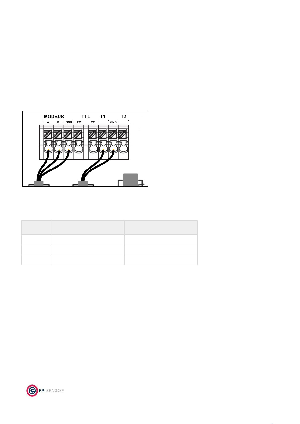
RS-485 Wiring
The ZMB includes a connector for both temperature probes and the Modbus/RS485 cable.
Label
Also Called
Also Called
A
RS485+
D1
B
RS485-
D0
GND
Earth
Ground
On long cable runs, a 120R terminating resistor is required at both ends across the A and B wires. Individual
drops do not need terminating resistors.
The cable should be a shielded twisted pair with the shield at one end connected to Earth / Ground. If the
system is earthed away from the ZMB, then the Shield/GND wire should not be connected to the ZMB.
The RS485 multidrop network is limited to 32 devices per network.
RS485 is popular for inexpensive local networks, multidrop communication links and long haul data transfer over
distances of up to 4,000 feet. However, the achievable distance is a function of the cable. The longer the cable,
Page 12 of 19

the greater the attenuation. Because attenuation increases with frequency, cables also exhibit a lowpass filter
behavior so that achievable distance diminishes with data rate.
The communications parameters are configured using the Gateway UI or the API. Because Modbus is the only
protocol implemented on the RS485 network, and Modbus always uses 8 data bits, the number of databits are
not configurable. The Baud Rate, Stop Bits and Parity are all configurable through the Gateway. All Slaves
connected to the ZMB must use the same communications parameters, and all slaves must use a unique Slave
Address on the Network.
TTL Wiring
The ZMB includes 3 terminals to achieve RS232 communications on the TTL connection. This is a point to point
connection and the Modbus network would be required to include just one Modbus Slave.
Label
Also Called
TX
RS232 Transmit
RX
RS232 Receive
GND
Ground
Modbus
For a full description of the Modbus specification please see https://modbus.org. Some specific details that
pertain to the ZMB devices are included here.
The ZMB implements Modbus RTU on the RS485 network. Modbus RTU allows up to 255 Slave addresses but
because of the RS485 limitation, there should be a max of 32 nodes on the multi-drop network. However, the
address range of 0-255 can still be implemented, provided there are a maximum of 32 physical nodes.
Furthermore, the ZMB has a maximum of 30 Modbus Sensors, which would mean if the maximum number of
physical nodes were connected to the Modbus cable, then two of them would be unreachable by the ZMB.
The ZMB implements Modbus Master. There should only be one Modbus Master (Modbus Client) on the
Modbus RTU network. Therefore all other nodes on the network are Modbus Slaves (or Modbus Servers).
The simplest method to configure a Modbus Slave that is connected to the ZMB is to use a “Node Profile”. Once
a specific set of slave addresses, register addresses, register types, lengths etc have all been configured and are
reporting correctly, the configuration from that node can be saved as a Node Profile. This Node Profile can then
be uploaded to any Gateway and applied to other ZMB nodes.
Configuration
The ZMB-3x must be configured as the only Modbus Master on the RS485 network. All other devices on the
network must be Modbus Slave devices. All Modbus devices on the network must communicate with the same
Page 13 of 19

communications parameters - those being the Baud Rate, Parity and Stop Bits. All Modbus devices must use 8
databits (if it is configurable).
Property ID
Setting
Description
Unit
Resolution
Reporting
Default
Read/Write
6410
Modbus Baud Rate
RS485 Communication Parameter for
Modbus Network
-
-
-
-
Read/Write
6411
Modbus Parity
RS485 Communication Parameter for
Modbus Network
-
-
-
-
Read/Write
6412
Modbus Stop Bits
RS485 Communication Parameter for
Modbus Network
-
-
-
-
Read/Write
The ZMB supports a number of Modbus functions;
●Read Coil 0x01
●Read Discrete Input 0x02
●Read Holding Register 0x03
●Read Input Register 0x04
●Write Coil 0x05
●Write Single Register 0x06
●Write Multiple Coils 0x0F
●Write Multiple Registers 0x10
For each of these functions, the corresponding Properties must be configured allowing the ZMB to interpret and
report the data in a meaningful format. The complete list of Modbus Properties are;
Property ID
Setting
Description
Unit
Resolution
Reporting
Default
Read/Write
6400
Modbus Address
The Slave Address of the unit on the
RS485 Network
-
-
-
0
Read/Write
6401
Register Address
The Register Address on the Slave.
This is zero based so may be 1 less
than the Register address listed in
any Slave device documentation
-
-
-
0000
Read/Write
6408
Read Function
The Modbus Read Fucntion for this
Sensor ID. There may be none!
-
-
-
0x00
Read/Write
6409
Write Function
The Modbus Write Function for this
Sensor ID. There may be none!
-
-
-
0x00
Read/Write
6404
Register Count
1 or 2. 1 Register is 16bits, 2
Registers are 32 bits
-
-
-
1
Read/Write
6407
Register Signed
Type
Is the value returned a signed or
unsigned value
-
-
-
False
Read/Write
6403
Register Float Type
Is the value returned a 32 bit
Floating point number as defined by
IEEE 754
-
-
-
False
Read/Write
6402
Bit Position
The position in the returned register
for “Coil” type reads/writes
-
-
-
0
Read/Write
6405
Register Byte Swap
Swap the Byte order in a 16 or 32 bit
-
-
-
False
Read/Write
Page 14 of 19

value
6406
Register Word
Swap
Swap the Word order in a 32 bit
value
-
-
-
False
Read/Write
Note: Error codes from Modbus are detected by the ZMB but are currently not reported to the Gateway.
Wireless Communications
All EpiSensor products use IEEE 802.15.4 ZigBee Pro for wireless communications operating at 2.4GHz. This is a
secure, scalable mesh networking communications protocol designed for transmitting small amounts of data
reliably, and at low power levels.
There are two types of nodes in the EpiSensor wireless mesh network: powered nodes and battery nodes.
Powered nodes on the wireless sensor network are capable of routing data from any other type of wireless
nodes.
Range extenders are powered nodes where the main function is to route data. Any node with a mains power
supply will act as a routing node in the network. Battery nodes do not route data – they spend most of the time
in a low power mode.
Each powered node can have up to 32 ‘neighbours’ which are nodes with a mains power supply and can Route
data back to the Gateway. They can also have up to 32 ‘children’ which are nodes that are battery powered and
cannot participate in any routing in the network.
The range that can be achieved with ZigBee will depend mainly on two factors: the power level of the ZigBee
radio module and the environment that the device is installed in. There are two types of ZigBee radio module
used across the EpiSensor product range, a power amplified version, and non-power amplified version.
The power output of nodes with a power-amplified module can be configured with an output power level of +20
dBm depending on the region they are deployed in. Non-power amplified nodes have a maximum output power
of +8 dBm.
Page 15 of 19

Module Type
Tx Power
Rx Sensitivity
LoS Range
Region(s)
Normal
+8 dBm
-101dBm
up to 300m (985ft)
Worldwide
Power-amplified
+20 dBm
-106dBm
up to 1600m (5250ft)
North America (FCC / IC)
All communications over the ZigBee wireless network is AES 128-bit encrypted. For more detailed information on
ZigBee security features, contact EpiSensor support.
Sensors
Reading Data
The ZMB reads data by polling each of the Modbus Sensors that have become due to report. The ZMB builds a
“Read Data” Modbus packet using the Sensor Settings parameters for Slave Address, Register Address, Read
Function and Register Count.
When the Modbus Slave replies, that reply is parsed using the Sensor Settings parameters for Signed Type, Float
Type, Bit Position (for Read Coil only), Byte Swap and Word Swap.
Depending on the model of ZMB, a number of generic Modbus sensors are available. They default to being
disabled and are not reporting data as none of the Register settings are available until configured.
Sensor ID
Data Feed
Description
Unit
Resolution
Reporting
Default
Read/Write
1100
Modbus Register 0
Generic Modbus Register that can be
used to interface with any connected
Modbus Slave
-
-
Off
-
Read/Write
….
1129
Modbus Register
29
Generic Modbus Register that can be
used to interface with any connected
Modbus Slave
-
-
Off
-
Read/Write
4097
Link Quality
Link Quality % - measure of
Zigbee signal
Off
60
Yes
4099
RSSI
Channel noise in dbm
Off
60
Yes
4101
Neighbour
Count
The number of mains
powered devices this device
can route messages through
Delta
and
Interval
360
Yes
4102
Child Count
The number of battery power
“child” devices that use this
device to route messages
through
Delta
and
Interval
360
Yes
Page 16 of 19

Additionally, the following sensor is available on ZMB’s that are supplied with a temperature probe:
Sensor ID
Data Feed
Description
Unit
Resolution
Reporting
Default
Read/Write
380
Temperature
Temperature Sensor
C
0.01C
15min
-
Read/Write
Page 17 of 19
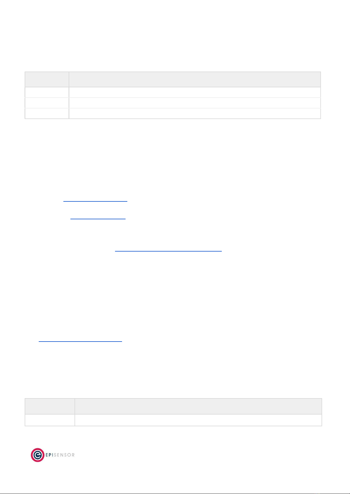
Ordering Information
EpiSensor products are available to order directly or via EpiSensor’s distribution partners. The following table
lists the available ZMB options.
SKU
Description
ZMB-30
Mains powered, single 2.5m waterproof temperature probe, max 4 Modbus registers, live stream mode
ZMB-31
Mains powered, no temperature probes, max 30 Modbus registers
ZMB-33
Mains powered, no temperature probes, max 4 Modbus registers, live stream mode
Troubleshooting & Support
If you are experiencing problems with your ZMB or any other part of your EpiSensor system, or you notice
something unusual - please contact EpiSensor support at the following email address, phone number or via live
chat on our website.
●Email: support@episensor.com
●Tel: +353 61 512 500
●Website: http://episensor.com
For customers and partners who are deploying systems in business-critical environments, there are a number of
support packages available that offer a higher level of service and response time. For more information on
EpiSensor Premium Support, visit: http://episensor.com/premium-support/
Warranty
All EpiSensor products and provided with a 365 day limited warranty effective from the shipping/invoice date of
an order. During the warranty period, under the conditions of normal use, EpiSensor will repair or replace any
product that has a manufacturing defect.
Warranty can be extended by up to 4 years within 30 days of a purchase. For more information on warranty,
visit: http://episensor.com/warranty/
Glossary
Definitions for terms and abbreviations used in this document are listed in the following table:
Term
Description
Sensor
Describes a feed of data within the EpiSensor system
Page 18 of 19

Node
Used to describe a physical EpiSensor product
Gateway
The central computer that managed the EpiSensor system
ZigBee
IEEE 802.15.4 Wireless communications standard that EpiSensor nodes use
WSN
Wireless Sensor Network
Reporting Mode
Defines how an EpiSensor node should report data to the Gateway
Reporting
Interval
The length of time between each data point produced by a node
Snap to Clock
Reporting mode where data is ‘snapped’ to the nearest 1 minute / 5 minute / 15 minute
interval etc.
Interval and
Delta
Reporting mode where data is produced when the reporting interval has elapsed, unless a
change is detected
Allow join mode
A mode that can be enabled on the Gateway that allows new wireless nodes to join
Page 19 of 19
This manual suits for next models
2
Table of contents
Other EpiSensor Recording Equipment manuals


Popular Recording Equipment manuals by other brands

Trinnov Audio
Trinnov Audio ST2-HIFI user guide

Yamaha
Yamaha MDR-1 Handling instructions

Cochlear
Cochlear Baha 5 SuperPower user manual

Daktronics
Daktronics Sportsound SSR-300 Operation manual

Creative
Creative PCB Assembly instructions

Whelen Engineering Company
Whelen Engineering Company CORE CenCom CV2V installation guide


