E+E Elektronik HUMLOG 10 User manual

StatusV2 (12/2003)
HUMLOG 10
Manual

Manual HUMLOG 10
Page 2 of 17
Contents
1 GENERAL 3
2 DISPLAY MODULE 4
3 HUMLOG 10 WITHINTERNALSENSORS 6
4 HUMLOG 10 TSE FOREXTERNALSENSORS 7
5 HUMLOG 10 THC WITHINTERNALSENSORS/WITHOUTDISPLAY 9
6 CHANGINGTHE SENSOR MODULE 13
7 CHANGINGTHE BATTERY 14
8 MOUNTINGTHE HUMLOG 10 15
9 SWITCHINGONTHE HUMLOG 10 16
10 TIPS AND TRICKS 17

Manual HUMLOG 10
Page 3 of 17
1 General
The HUMLOG 10 product family is a newdevelopment fromthe E+E ELEKTRONIK,
which standsout fromthe field due to itsexcellent price / performance ratio.
The compact design with itsmodulartechnologyfacilitatesa multiplicityof
applications.
The measurement valuescan be read very well on the large displayfroma distance
of severalmetres.
HUMLOG 10 family:
HUMLOG 10 =humidity/temperature internal
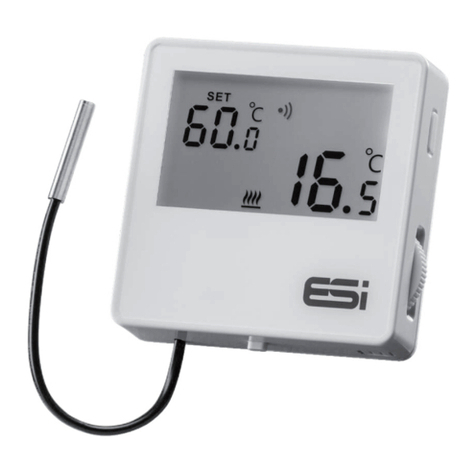
HUMLOG 10 TSE =humidity/temperature external, with 2-channels to which either2
temp. probesor1-2 combined humidity/temp. probe can be connected
HUMLOG 10 THC =humidity/temperature internal(without display)
Due to itsextremelylowenergyconsumption and large memory, the product is
excellentlysuited to long termmeasurement in both mobile and stationery
applications.
The SmartGraph 2 software, which is included with the product, offersthe useran
overviewpresentation and simple data archiving.
With the professionalversion of SmartGraph 2, the valuesfortemperature and dew -
point can be shown on the displayoptionallyin °C or°F, and the humidityin %
(relative humidity) orin g/m³(absolute humidity).
The technicaldata of the HUMLOG 10 can be found on the internet :
http://www.epluse.net

Manual HUMLOG 10
Page 4 of 17
2 Display Module
The HUMLOG 10 generallyconsistsof two modules: a DisplayModule and a
SensorModule.
The memory, realtime clock and the microprocessorcontrollerare located on the
DisplayModule.
Illustration: HUMLOG 10 DisplayElements
AlarmChannel1
AlarmChannel2
SpecialFunctions
Channel1Unit
Channel2Unit
REC: Recording “On“
STOP: Recording “Off“
Display: PreselectionMode: Active
Display: RealTimeClock
Alternative Display of date/timefor thepreselectionor
realtime
Format Date: 12.10
Format Time: 12:10

Manual HUMLOG 10
Page 5 of 17
Explanations concerning the Displayoperation:
When a pre-set limit hasbeen exceeded the alarmsymbolof the corresponding
channelflashes. Once an alarmhasbeen recognised, the alarmsymbolremains
visible on screen in static formeven if the limit is no longerexceeded. The alarm
message can onlybe eliminated byselecting “Memory Readout”on the PC.
If the Pre-Selection mode (start flag)wasselected, the start-date and start-time for
data recording are shown on the Date/Time display. Once the pre-set date/time has
been reached the start flag is eliminated, the realtime clock displaybecomesactive
and data recording begins.
The unitsm/s(Channel1)and ppm/ hPa (Channel2)are reserved forotheroptions.
The specialfunctionsare reserved forotheroptions.

Manual HUMLOG 10
Page 6 of 17
3 HUMLOG10 with Internal Sensors
The sensorsfortemperature and relative humidity, the corresponding sensor
adapters, and the serialinterface (RS232)are located on this module.
Illustration: Module with InternalSensors
Necessary calibration intervals are dependent on the environmentalconditionsand
the requirementsof the permissible tolerance deviations.
Asingle point calibration of the internalsensorscan be carried out using a
comparison standard. The captured offset valuescan be entered in the SmartGraph
software under: Measuring Instrument / Manage Measuring Instrument / Sensor
Electronics.
Two point calibrationscan onlybe carried out in the factory.

Manual HUMLOG 10
Page 7 of 17
4 HUMLOG10 TSE forExternal Sensors
The connectorsforthe externalsensors, the corresponding sensoradaptersand the
serialinterface (RS232)are located on this module.
Illustration: Module forExternalSensors
Eitherone ortwo temperature sensorsorone to two combined
temperature/humiditysensorscan be connected here. (Two sensorsare only
available in connection with the Professionalversion of SmartGraph 2.
If onlyone externalsensoris used this is connected to the left hand sensorsocket.
In orderthat the instrument maycorrectlyrecognise the association of the sensors
to the channels, both sensorsocket positionsmust first be unoccupied. If a sensor
is connected to one of the two sockets, the indication UPLG (Unplug)appearsin the
corresponding line (Line 1=left hand socket, Line 2=right hand socket).

Manual HUMLOG 10
Page 8 of 17
If both socket positionsare free, the indication SENS appearsin the upperline, and
the first sensorcan be connected to the left hand socket position.
There are now10 secondsavailable (Countdown on the display) to connect an
optionalsecond sensorto the right hand socket position.
Necessary calibration intervals are dependent on the environmentalconditionsand
the requirementsof the permissible tolerance deviations.
Asingle point calibration of the externalsensorscan be carried out using a
comparison standard. The captured Offset values can be entered in the SmartGraph
software under: Measuring Instrument / Manage Measuring Instrument / Sensor
Electronics.
Two point calibrationscan onlybe carried out in the factory.
Instructionsforusing additionalextensionsforthe probes:
The probesare adjusted forthe standard cable with a length of 2m.
Byusing extension cablesforthe probesthe accuracyof the measured relative
humiditydegrades.
Using an additionalextension cable with a length of 2mor4m: no change of the
humidityoffset isnecessary.
Using an additionalextension cable with a length of 6m: set an offset value of –0.8%
in the software SmartGraph.
Using an additionalextension cable with a length of 8mor10m: set an offset value
of –1.8%in the software SmartGraph.
Go into software SmartGraph and performfollowing step:
- instrument ->configuration of instrument
- select the instrument
- sensors -> settings(relative humidity)
- enterthe offset asdescribed above

Manual HUMLOG 10
Page 9 of 17
5 HUMLOG10 THC with Internal Sensors/without Display
General: the hardware of the HUMLOG10 compact is almost identicalto the
hardware of the HUMLOG10 with display. Two LEDs(a red and a green one)are
used asa sub-stitute forthe displayto indicate the operation mode and the alarm.
In addition, you will find close to the serialinterface a start / stop button to switch on
/ off the datalogger.
Operation mode / Alarm
Serialinterface
Start-/ Stop button

Manual HUMLOG 10
Page 10 of 17
Start/Stop function: the off / on button enablesthe HUMLOG10 to start and stop
recording. The manualactivation / deactivation of the dataloggerand the
configuration in start/stop orin ring mode are independent.. Bypressing the off / on
button, the HUMLOG10 will start recording ; bypressing it again, the HUMLOG10
will stop etc...
Important: In the start / stop mode, the HUMLOG10 will start recording fromthe
start date on (provided that this date is set in the HUMLOG) no matterif the start /
stop button is being pressed during this time.
Before the HUMLOG startsrecording, it can be activated ordeactivated too via the
on / off button (s. timing diagram).
Button On
Button Off
Logger On
Logger Off
LED Green
LED Red
Timing Diagram: HUMLOG 10 THC inring mode

Manual HUMLOG 10
Page 11 of 17
Button On
Button Off
Logger On
Logger Off
LED Green
LED Red
Timing Diagram: HUMLOG 10 THC instart-/stop mode
The button should be kept pressed forapprox. 1 sec. to start / stop the HUMLOG10.
When activating the HUMLOG10, the green LED remainson during 3 sec. The red
LED remainson during 3 sec. when deactivating the HUMLOG10.
While recording, both LEDson the HUMLOG10 orjust one of themwill flash at 10
secinterval. This time intervalis completelyindependent of the recording and
storage intervals set bythe userin the HUMLOG10.
Programmed start date

Manual HUMLOG 10
Page 12 of 17
Alarmfunction: the dataloggeris equipped with an alarmfunction on both channels
(temperature and humidity) which enablesthe userto set minimumaswell as
maximumlimit values.
The red LED will flash in case of an alarm.
If an alarmoccurswhile the HUMLOG10 is recording, the green LED will switch off
and the red LED will start flashing.
As soon asthe measured valueshave become normalagain, both LEDswill flash to
signalthat an alarmcame up. This can be reset byreading out the memory.
Timing Diagram: HUMLOG 10 THC alarms
Measuring value
Set point
LED Green
LED Red
Readout ofdatamemory

Manual HUMLOG 10
Page 13 of 17
6 Changing the SensorModule
To change the SensorModule please carefullyremove the HUMLOG 10 back-plate
with a screwdriver. The SensorModule can nowbe detached fromthe display
Module.
Place the newSensorModule on the displayModule guide rail and push the two
modulestogetheruntil theyengage.
Illustration: Removing the Back-Plate
Illustration: Assemblyof the Modules

Manual HUMLOG 10
Page 14 of 17
7 Changing the Battery
When the indication BAT flashesin the upperline of the display, the battery must be
changed.
In orderto do this, please first remove the SensorModule (see Changing the Sensor
Module).
Please remove the fourscrewson the rearof the DisplayModule, using a suitable
screwdriver.
Laythe DisplayModule on a flat surface, with the displayfacing upwards, and
carefullyremove the upperpart of the plastic cover.
Nowremove the old battery and fit the newbattery (Type: LS14500/Saft, 3.6V; Order
No: HA03 01 02)into the holder.
Important: Please observe the correct polarityof the battery and read the safetytips
on the battery.
The BAT indication nowdisappearsand the measurement valuesare shown again
on the display.
The battery should be changed annually. Frequent data transferwith the PC and low
sample ratesreducesbattery life.
Illustration: Opening the HUMLOG 10 Illustration: Changing the battery
to change the battery

Manual HUMLOG 10
Page 15 of 17
8 Mounting the HUMLOG10
The HUMLOG 10 can be used asa mobile and stationary data acquisition system.
Forstationary applicationsthe HUMLOG 10 mayonlybe mounted on a flat surface.
In orderto do this, please first remove the SensorModule (see Changing the Sensor
Module).
Two holesforwall mounting are provided in the guide rail of the DisplayModule.
Use these to mount the DisplayModule. Next carefullyjoin the two modules
togetheruntil theyengage.
Illustration: Mounting the HUMLOG10

Manual HUMLOG 10
Page 16 of 17
9 Switching on the HUMLOG10
Just to take care of the battery the HUMLOG 10 the HUMLOG 10 is switched off
during the delivery period.
Commissioning:
install and open the enclosed evaluation software SmartGraph on yourPC
(insert Disk 1/2 and run: setup_humlog10.exe)
Connect the data loggerand the serialinterface of yourPC using the supplied
transfer - cable
Open the menu – selection instrument and chose the command read
configuration
As soon asthe first communication hasbeen successfullythe measuring values
appearon the displayand the HUMLOG is readyforoperation.
Remark:
If difficultiesshould occurduring the communication kindlycheck yourinterface –
settings. (furtherinformation see menu selection help within the SmartGraph
software)

Manual HUMLOG 10
Page 17 of 17
10 Tips and Tricks
Please change the battery annually(Type: LS14500/Saft, 3.6V;
OrderNo: HA03 01 02).
Frequent communication with the PC reducesbattery life.
Please use onlythe cable supplied forPC data transfer.
Please avoid condensation on the sensorelectronics and HUMLOG 10.
Forthe entire information and furtherdetails regarding handling, configuration
and evaluation of the data loggerkindlyhave a lookat the menu – selection
help at the enclosed SmartGraph Software.
Table of contents
