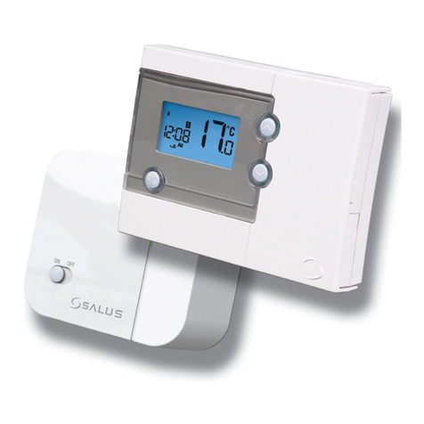
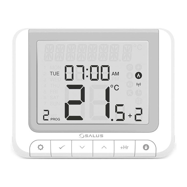
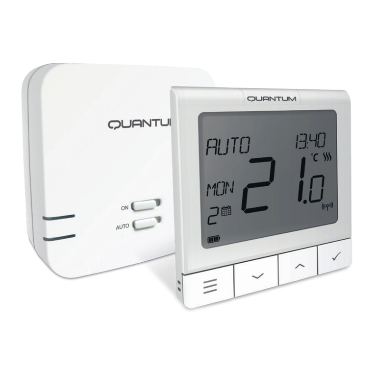
Salus WBNTSQ61024 Quantum User manual

IX 2019
THERMOSTAT 24V
SMART HOME
READY
WIRELESS
CONTROL
24V POWER
SUPPLY
COMFORT
OF A WARM FLOOR
IX 2020
MULTIFUNCTIONALITY
EASY
INSTALLATION
HUMIDITY
SENSOR
5YEAR
WARRANTY

2
UseinaccordancetonationalandEUregulations.Usethedeviceasintended,keepingit in dry condition.Productfor
indoor use only. Installation must be carried out by a qualified person in accordance to national and EU regulations.
Disconnect your equipment before cleaning it with a dry cloth.
Please always ensure the AC 24V mains power is switched off before installing or working on any components.
Safety Information
Warning:
Package Content:
1) WBNTSQ61024 Thermostat
2) Mounting screws
3) Manual instruction
Introduction
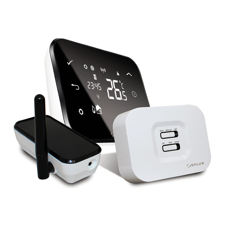
The WBNTSQ61024 Quantum is a ZigBee temperature controller for wireless control of iT600 series devices,
such as the KL08RF wiring centre, miniTRV head, RX10RF boiler control module.
In order to control WBNTSQ61024 over the Internet or via the Smart Home mobile app (ONLINE
mode), it must be installed together with the UGE600 Internet gateway (sold separately). From the application
level, it is possible to pair WBNTSQ61024 with other system elements, e.g. Smart Plug SPE600, Smart Relay
SR600 or window/door sensor OS600/SW600.
WBNTSQ61024 can be used locally without an Internet connection (OFFLINE mode), however, it’s
communication with other devices must be done using the CO10RF coordinator (sold separately).
THERMOSTATWBNTSQ61024QuantumcanworkwithoutUniversalGatewayorCO10RF Coordinatorasastandalone
device.
Full manual in PDF format is available at www.salus-controls.eu site.
Product Compliance
This product complies with the essential requirements and other relevant provisions of Directives 2014/30/ EU,
2014/35/EU, 2014/53/EU and 2011/65/EU. The full text of the EU Declaration of Conformity is available at the
following internet address: www.saluslegal.com 2405-2480MHz; <14dBm
3
Svenska Dansk English
Before you start: Wiring diagram:
Symbols explanation:
S - volt-free contact
T - temperature sensor
L1, L2 - 24V AC pover supply
COM, NO - Voltage free output
S1,S2 Terminals:
- air or floor temperature sensor
- external volt-free contact to connect anyON/
OFF switchor occupancy sensor (Hotel card)
Mounting: to mount thermostat you can use included
accessories (mounting screws). Remove plate from
the back to mount it to the wall. After that just put
thermostat on the plate.
Please note:
The ideal position to thermostat mounting is about 1,5m
under floor level far from heating or cooling sources.
Thermostat can’t be exposed to sunlight or any extreme
conditions like for example draft.
MM
150 cm
min 20 cm
Select correct thermostat location
L
S1 S2
N
T
S
AC 24V
24V AC

4
1. Menu/Settings description + Clock
2. AM/PM
3. Temperature unit
4. Heating indicator (icon is animating when
there is heating demand)
5. Cooling indicator (icon is animating when
there is cooling demand)
6. RF Connection indicator
7. Internet connection indicator
8. Occupancy sensor (hotel card)
9. Key lock function
10. Standby mode icon
11. Current Temperature / Setpoint Temperature
12. Holiday mode
13. Temporary override mode
14. Settings icon
15. External / Floor temp sensor indicator
16. Schedule program number
17. Schedule mode icon
18. Day indicator/ SET information
19. Current Humidity value
2
8
9
10111214
19
18
17
16
15
1
3
4
5
6
7
13
LCD Icon Description

5
Buttons Description
Buttons Description
1) Menu button / Return button.
2) In the MAIN SCREEN: Press and hold for 3 sec to change the thermostat operating mode
(Schedule mode / Permanent mode /Temporary override mode).
3) In the SETTINGS SCREEN:
Press and hold for 3 sec to go back without saving the changes.
4) In the PAIRING SCREEN (in SYSTEMTYPE Menu): Press and hold for 3 sec to see other
pairing options.
+
In the MAIN SCREEN - press and hold these buttons together for 3 seconds to LOCK / UNLOCK
the Thermostat keys).
“Up”Button (Increase parameter value/moving on the menu in‘UP’direction)
„Down”Button (Decrease parameter value/moving on the menu in‘DOWN’direction)
1)“OK /Tick”Button (Confirm parameter value / Go to the next menu / Save settings)
2) In the MAIN SCREEN: Press and hold for 3 seconds to enter Standby mode
3) In the SETTINGS SCREEN: Press and hold for 3 sec to go back to the MAIN SCREEN & SAVE all the changes.
Button Function
Svenska Dansk English

6
COMPATIBILTY WITH OTHER SALUS CONTROLS DEVICES
Quantum Thermostat can work in ONLINE or OFFLINE mode. *
At first step you need to decide in which mode your thermostat will work.
ONLINE MODE OFFLINE MODE
Universal Gateway is
CONNECTED TO THE INTERNET
You canconfigure and useall your
devices in the Smart Home App
Download the Smart Home
App on your iOS or Android
devicefor remoteaccess toyour
SALUSequipment. SALUS
Smart Home
CO10RF Coordinator - You can use
standard ZigBee network coordinator
toinstalland use your devices.
Universal Gateway is NOT
CONNECTED TO THE INTERNET
You can use your devices locally
without the SmartHome App.
Gateway works in this mode as
standard ZigBee coordinator.
Compatibile devices:
KL08RF
Wiring Centre for 8-zone
underfloor heating (UFH).
TRV
(Thermostatic
Radiator Valve) with
wireless communication.
RX10RF
receiver
SR600*
Smart Relay SPE600*
Smart Plug
OR
WBNTSQ61024 Quantum Thermostat can work without coordinators
(ONLINE/OFFLINE MODE) as a standalone device with the wires use.
*Only with Online Mode
GET IT ON
Download on the
Please note:

7
First power up sequence
Topower on theThermostatyou have
toconnect it tothe 24V powerthen...
For easier installation, please make sure you have already added other devices to your ZigBee network, such as
Underfloor Heating Control Box (KL08RF) or Radiator heads (TRV’s) etc.
Please note:
Now, choose your language by
„” or „ ”buttons.Confirm
your language by button.
...display will showall icons... ...then thermostat will display
the software version.
2
1
4
3
5
Thermostat work as a standalone device
for pump, boiler, receivers etc. That is, you
candirectly connectthermostat toselected
device without any network system. You
canadditlateranytime.
NO - STANDALONE.
You can configure your thermostat
with universal gateway or CO10RF
coordinator.Thatis, add it tothe Salus
Smart Home system.
YES - ONLINE, OFFLINE MODE.
Svenska Dansk English

8
Installation in ONLINE mode
AfterLanguage selection followbelowstepsto add yourdevicetothe Smart Home appand pair withother devices:
21
SALUS
SmartHome
Go to SALUS Smart Home app
3
Once your thermostat is added to
the app you will see above screen
on the LCD.
9
7
45 6
8

9
10
13
Afterthatthermostatwillshow
mainscreen.
Congratulations!
Yousuccesfullyconfiguredyour
Quantum Thermostat.
15
14
1211
Name this equipment
QUANTUM Room Thermostat
Connect equipment
Finish
Svenska Dansk English

10
Installation in OFFLINE mode
123
Open the ZigBee network
456
Select system type: UNDERFLOOR,
press button to confirm
Using and buttons select the Control
Box number (press PAIR button on the Control
Box tosee itsaddress number).Press button
to confirm
Use or buttons to select
the zone number and press
button to confirm.
8
7
Now you can pair your thermostat
with additional zones. Select one
more zone or finish the pairing
process by button.
OR
5 sec
5 sec
9
Close the ZigBee network
OR
5 sec.
5 sec
Pairing with Wiring Centre / Control Box (Installthe Wiring Centre / Control Box accordingto the
instructionsincluded with product)

11
7
54
3
6
Open the ZigBee network
Select system type:
RADIATORS
Now hold antenna button for 10
sec. on all TRV’s which you want
to pair with yourTermostat.
Pairing with TRV radiator head (Install the TRV accordingto theinstructions includedwith
product)
On the LCD you will see the number of
pairedTRV’s. Once all TRV’s are paired - press
button to finish the pairing process.
OR
5 sec
5 sec.
10sec
12
98
Close the ZigBee network
OR
5 sec
5 sec
You can pair up to 6 TRV’s with
1 Thermostat. All TRV’s have
to within the same room with
Thermostat.
Svenska Dansk English

12
Wired device
ThermostatWBNTSQ61024 Quantum can work without Universal Gateway or CO10RFCoordinator asa standalone
device.
Please note:
Wiring diagram for volt-free connection (e.g. boiler control):
1
2Wiring diagram for AC 24V connections:
AC 230V
S1
S2
BOILER CONNECTIO
N
S1
S2
AC 230V
COM NO
COM NO *
MAX 3(1)A
S
AC 24V
AC 24V
L1
L1
L2
L2
L1
L1
L2
L2

13
Please note:
3Wiring diagram for control box connection:
Legend:
Boiler connection * - Boiler’s contacts
for ON/OFF thermostat (according to the
boiler’s instructions)
Pump
Boiler
Valve actuator
Heating mat
Self-acting WBNTSQ61024 Quantum Thermostat without application support can be easily
added to the Smart Home app anytime. All settings made before adding to the application are
automatically copied to the Smart Home app.
N
1-8 Zones
SLL
S1
S2
AC 230V
Power
NO
N
L
COM
KL08NSB
S
AC 24V
L1
L1 L2
L2
Svenska Dansk English

14
WBNTSQ61024 Full menu structure
Schedule settings
User settings
Admin settings
Language
TIME/DATE
HOLIDAY MODE
THERMOSTAT CALIBRATION
SHOW/HIDE DISPLAY HUMIDITY
SHOW/HIDE DISPLAY FLOOR
STANDBY TEMP SETPOINT
HEAT/COOL
RESET USER SETTINGS
ENGLISH
DANISH
POLISH
...
DISABLE
MO-FR+SA-SU
MO-SU
SINGLE DAYS
Main menu
TEMPERATURE SCALE
DISPLAYTEMPERATURE RESOLUTION
1.
HEAT CONTROL ALGORITHM
2.
COOL CONTROL ALGORITHM
S1/S2 INPUT
3.
MINIMUM SETPOINT
MAXIMUM SETPOINT
VALVE PROTECTION
4.
INTERNAL RELAY (ENABLE/ DISABLE)
RELAY TYPE (NO / NC)
MINIMUMTURN OFF TIME
6.
OPTIMISATION FEATURE
7.
COMFORTWARM FLOOR
8.
PIN CODE
DEVICE INFORMATION
9.
CONNECTWITH GATEWAY
FACTORY RESET
10.*

15
Short description of some selected functions (all functions are described
inthe fullversion of the WBNTSQ61024 manual):
1. DISPLAY TEMP RESOLUTION: This function determines the resolution of the displayed
temperature ( 0.5°C or 0.1°C ).
2. CONTROL ALGORITHM: This function defines how to control the room temperature. Available
optionsare:ITLC for Underfloor Heating / Radiators / Electrical Heating (that’s advanced algorithm for
precise maintenance of room temperature), hysteresis +/-0.5°C or +/-0.25°C, THB Actuator (option
recommended for systems with THB auto balancing actuators).
3. S1/S2 INPUT: A floor sensor, an external temperature sensor or an occupancy sensor can be
connected to the S1/S2 input of WBNTSQ61024RF. Additionally, by connecting a NO type of ON/OFF
voltage-free contact, you can use this input as a OneTouch rules trigger (programmed in the Salus
Smart Home app) or as a Heat/Cool changeover.
4. VALVE PROTECTION: This function activates all actuators once a week for 5 minutes (in summer,
this function helps to prevent the actuators stuck).
6. MIN TURN OFF TIME: Minimum switch-off time (thermostat will not send the signal for
heating/cooling more often than specified in this parameter).
7. OPTIMISATION FEATURE: Optimum Start and Optimum Stop functions are energy saving feature
that makes thermostat most cost effective (in combination with ITLC control algorithm).
9. DEVICE INFORMATION: In this menu user can check: Software Version, RF range value, Paired
devices or also user can activate Identification mode.
*10.FACTORYRESET:Hereyou can RESET yourdeviceto factory settings. After successfullreset
device will be removed from ZigBee network and you will need to add / pair your device again.
8. COMFORT WARM FLOOR: This function helps to keep the floor warm, even if the room is warm
enough and there is no need to turn on the heating. User can select 3 levels of warm floor feature.
Pleasenoteit is not an economy feature,as your heating system may beON even if there is no heating
demand from the room thermostat. It is COMFORT feature which keeps your floor warm all the time.
5. INTERNAL RELAY (COM/NO): Internal relay activation or deactivation with COM/NO outputs use. Default
is enable.
Svenska Dansk English

16
Intruduktion
Quantum rumtermostaten er en ZigBee-termostat som tradlos arbejde sammen med iT600-serien,
f.eks. KL08RF kontrolboks, miniTRV, RX10RF kedelstyremodul mm. For at kontrollere Quantum termosataten
over internettet eller via SALUS Smart Home-mobilappen (ONLINE-tilstand), skal den installeres sammen med
UGE600 Internet gateway (sælges separat).
Fra appen er det det muligt at parre Quantum rumtermostaten med andre systemelementer, f.eks. Smartstik
SPE600, Smart Relay SR600 eller vindue / dørsensor OS600 / SW600.
Quantum termostaten kan bruges lokalt uden en internetforbindelse
(OFFLINE-tilstand), men det er kommunikation med andre enheder skal udfores ved hjalp af
CO10RFkoordinatoren (sælges separat).
Quantum rumtermostaten kan fungere uden Universal Gateway eller CO10RF-koordinator som en selvstændig
enhed.
Produktoverensstemmelse
Anvend i henhold til bestemmelserne. Anvend udelukkende inde døre. Hold din enhed helt tørt. Afbryd enheden,
før den rengøres med en tør klud.
Sikkerhedsoplysninger
Dette produkt er i overensstemmelse med de grundlæggende krav og andre relevante bestemmelser i
Direktiverne 2014/30/EU, 2014/35/EU, 2014/53/EU and 2011/65/EU. Den komplette tekst, der indeholder
overensstemmelsesdeklaration angående EU-direktiverne, kan findes på følgende internetadresse:
www.saluslegal.com
Pakken indeholder:
1) Quantum Rumtermostat
2) Montage skruer
3) Instruktions manual
Vær opmærksom på at strømmen AC 24V er slå fra ved montering.
Advarsel:

17
Før du starter:
Vælg den korrekte termostat placering
El-diagram:
Symbol Forklaring:
S - voltfri kontakt
T - Temperatursensor
L1, L2 - 24V AC forsyning
COM, NO - Spændingsfri udgang
S1,S2 Terminaler:
- Luf eller gulv sensor
- ekstern voltfri kontakt kan tilslutte en hvilken
som helst ON / OFF switch eller
belægningssensor (Hotel kort),kan tilsluttes
Montering: For at montere rumtermostaten på væggen
kan du bruge de inkluderede monteringsskruer. Fjern
bagpladen for at montere den på væggen. Efter dette
skal du placere rumtermostaten på pladen.
Bemærk venligst:
Den ideelle position til montering af rumtermostat er ca.
1,5 m over gulvniveau langt fra varme- eller kølekilder.
Termostat bør ikke udsættes for sollys eller ekstreme
forhold som f.eks. Træk.
MM
150 cm
min 20 cm
Svenska Dansk English
L
S1 S2
N
T
S
AC 24V
24V AC

18
1. Menu / indstillingen beskrivelse + Ur
2. AM/PM
3. Tempetur enhed
4. Varmeindikator (ikonet er animeres,
når der er et varme kald)
5. Køleindikator (ikonet er animeres,
når der er et køling kald)
6. Ikon for trådløs forbindelse
7. Ikon for internet forbindelse
8. Belægningssensor (hotelkort)
9. Låse funktion til termostaten
10. Standby mode ikon
11. Temperatur indikator
12. Ferie mode
13. Imidlertid overstyring af temperatur
14. Indstillings ikon
15. Extern sensor indikator
16. Program nummer indikator
17. Tidsplan ikon
18. Dag indikator
19. Luftfugtighed
2
8
9
10111214
19
18
17
16
15
1
3
4
5
6
7
13
Beskrivelse af LCD Ikoner

19
Knap beskrivele
Knap beskrivele
1) Menu knap / Retur knap.
2) HOVEDMENU:Tryk og hold nede i 3 sek for at ændre termostatens driftstilstand (Tidsindstilling /
Permanent indstilling / Midlertidig overstyring).
3) Under INDSTILLINGSSKÆRMEN: Tryk og hold nede i 3 sekunder for at gå tilbage uden at gemme
ændringerne.
4) I PAIRING SCREEN (i SYSTEMTYPE-menuen): Tryk og hold nede i 3 sekunder for at se andre
parringsindstillinger.
+
Under temperaturvisning - tryk og hold pil op og pil ned knapperne samtidigt for 3
sekunder for at låse termostaten
„Pil op”Knap (Hæv temperaturen /bevæger sig i menuen i ‹Op› retning)
„Pil ned”Knap (SænkTemperatur /bevæger sig i menuen i‘Ned’retning)
1)“OK / Flueben -knap (Bekræft indstilling / Gå til næste menu / Gem indstillinger)
2) Under temperaturvisningen: Tryk og hold nede i 3 sekunder for at gå ind i standbytilstand
3)Under INDSTILLINGSSKÆRMEN:Trykog hold nede i3 sekunder for atgåtilbage til hovedskærmen og
gemme alle ændringerne.
Svenska Dansk English
Knap Funktion

20
KOMPATIBILITET MED ANDRE SALUS PRODUKTER
Quantum termostaten kan virke med og uden forbindelse til internettet(App)
Som det første trin skal du beslutte er i hvilken mode din termostat skal fungere
ONLINE MODE OFFLINE MODE
Universal Gateway er
TILSLUTTET TIL INTERNETTET
Du kan konfigurere og bruge
alle dine enheder i Smart
Homeappen
DownloadSmartHomeappen
på din iOS - eller Android-
enhed og få adgang til dit
SALUS-udstyr. SALUS
Smart Home
CO10RF-koordinator- Dukanbruge
standardZigBee-netværkskoordinator
tilatinstallere og bruge dine enheder.
Universal Gateway er IKKE
forbundet TIL INTERNETET
Du kan bruge dine enheder lokalt
uden SmartHome-appen. Gateway
fungerer i denne tilstand som
standard ZigBee-koordinator.
Kompatible enheder:
KL08RF
Kontrolboks til 8 zoner
gulvvarme (UFH)
TRV
Trådløs aktuator til
radiator ventil.
RX10RF
Modtager
SR600*
Smart Relæ SPE600*
Smart Plug
OR
Quantum Rumtermostat kan arbejde uden CO10RF eller UGE600
*Only with Online Mode
GET IT ON
Download on the
Bemærk venligst:
7
Opstartssekvens
For at starte rumtermostaten skal du
slutte den til 230V derefter ...
Forden letteste installation skal du sørgefor,at du alleredehar føjet andre enheder til dit ZigBee-netværk, f.eks.
Gulvvarme-kontrolboks (KL08RF) eller radiatorhoveder (TRV’er) osv.
Bemærk venligst:
Vælg nu dit sprog med knapperne
„ ” eller „ ” Bekræft dit
sprog med knappen .
... display viser nu alle ikoner ... ...nu viser rumtermostaten
softwareversionen.
2
1
4
3
5
Rumtermostat fungerer som en
enkeltstående enhed til pumpe, kedel,
modtagere osv. Det vil sige, du kan direkte
forbinde rumtermostaten til den valgte
enhed uden noget netværkssystem. Du
kantilføjedettilnetværketsenere.
YES - ONLINE, OFFLINE MODE.
NEJ - STANDALONE.
Du kan kongurere din rumtermostat
med universal gateway eller CO10RF-
koordinator. Det vil sige føje den til et
Salus Smart Home-system.
Svenska Norsk
Suomaleinen Dansk
Table of contents
Languages:
Other Salus Thermostat manuals

Salus
Salus ST101ZB User manual

Salus
Salus RT500ROF User manual

Salus
Salus ERT30 User manual

Salus
Salus VS20 User manual

Salus
Salus Quantum SQ610 User manual

Salus
Salus FT100 User manual

Salus
Salus ERT20RF User manual

Salus
Salus RT510RF User manual

Salus
Salus Optima S User manual

Salus
Salus RT310SR User manual

Salus
Salus TS600 User manual

Salus
Salus RT510RF User manual

Salus
Salus RT310i User manual

Salus
Salus QUANTUM SQ610RF User manual

Salus
Salus Optima S User manual

Salus
Salus HTR24 User guide

Salus
Salus AWRT10RF User manual

Salus
Salus RT500BC User manual

Salus
Salus HTRS230V(30) User manual

Salus
Salus Quantum SQ610 User manual