EPOX P55-KV User manual

Introduction1-1
Chapter 1
Introduction
The P55-KVmainboard is a high performance system hardware based on
Intel Pentium processor and is equipped with two PCI slots, three standard
ISAslots,SuperMulti-I/OcontrolleranddualportPCI-IDEconnectorsfor
thefutureexpansion.Thehardwaredimensionis220mmx190mmwitha
four-layer-design technology.
Specification
VIAVT82C580VPXPCIsetchipset.
Intel Pentium Processor, AMD K5 & Cyrix M1 operating at75~200MHz
and P55C with 321 ZIF socket 7 and scalability to accept faster Processors
in the future.
Supports up to 128 MegaBytes of DRAM (a minimum of 4 MB) on board
(72PinsSIMMx2). BIOSwillautometicallydetectandconfigureFPDRAM
andEDODRAM(RefertoChapter 2-4SystemMemoryConfiguration).
Supports Onboard Pipelined Burst (synchronous) L2WriteBack Cache.
Thecachememorycombinationcanbe256KB/512KB(32KB*32,64KB*32
SRAM,respectively).
Supports three 16 bit ISA slots, two 32 bit PCI slots, and provides two
independent high performance PCI IDE interfaces capable of supporting
PIOMode3andMode4devices.TheP55-KVsupportstwoPCIBus
Masters and a jumperless PCI INT# control scheme which reduces configu-
rationconfusion whenplugginginPCII/Ocontrollercard(s).
SupportsATAPI(e.g.CD-ROM)devicesonbothIDEinterfaces.
Supports 1 floppy port, 1 parallel port (EPP,ECP port), and 2 serial ports
(16550FastUARTcompatible).
Supports a PS/2 style mouse and standard AT style keyboard connectors.
Supports Award Plug & Play BIOS . The BIOS is stored in Flash EPROM
form. It provides better upgradeability for the system.
Supports CPU Hardware sleep and SMM (System Management Mode).
P55-KVutilizesLithiumbatterywhichprovidesenvironmentalprotection
and longer battery life.
R
R

1-2 P55-KV
82438
PCI#1
PCI#2
<
BIOS
K/B
CONN.
Power Conn.
PRINTER
COM2
P55-KV Layout
COM1
SIMM 1
SIMM 2
Primary IDE
Secondary IDE
FDD CONN.
J1
Socket7
J2
J6
J5
J4
J8
J7
J9
KEY-LOCK SPEAKER RESET SLEEP TB-LED HD-LED G-LED
+++
J10
J11
Figure 1-1
W83877
82C587
82C587
32K*32
32K*32
82C586A
82C585VPX
J3

Hardware Design 2-1
2-1 Mainboard Layout
Chapter 2
Hardware design
TheP55-KVisdesignedwithVIA82C580VPXPCIsetchipsetwhichisdeveloped
by VIA Corporation to fully support Pentium Processor PCI/ISA system. The VIA
82C580VPXPCIsetchipsetprovidesincreasedintegrationandimprovedperformance
designs. The chipset provides an integrated IDE controller with two high perfor-
mance IDE interfaces for up to four IDE devices (hard devices, CD-ROM device, etc).
The Winbond W83877F Super I/O controller provides the standard PC I/O functions
including:floppyinterface,two16ByteFIFOserialportsandEPP/ECPcapable
parallel port. TheP55-KV layout is shown in the previous page (left page) for user's
reference.Caremustbetakenwheninsertingmemorymodules,insertingCPUor
even plugging PCI cards into the associated slots to avoid damaging any circuits or
sockets on board. A cooling fan is strongly recommended when installing P54C/
P54CTB/P55C/K5/6x86processorduetopossibleoverheat.
TheP55-KVsupportsaminimumof4MBofSystemMemoryandamaximumof
128MBwhileL2Cachecanbe256KB/512KBsynchronousSRAMOnboardto
increasesystemperformance(Referto Page2-6CacheMemoryConfigurationfor
thedetails).
The P55-KV supports standard Fast Page and EDO (Extended Data Out or Hyper
Page Mode) .TheP55-KVprovides two 72-pin SIMM for memory expansion. The
socketssupport1Mx32(4MB),2Mx32(8MB),4Mx32(16MB),and8Mx32(32MB)
single-sided or double-sided memory modules. The memory timing requires 70 ns
Fast page devices or 60 ns EDO DRAM. (DRAM Modules may be parity[x 36] or
non-parity[x32].
TheP55-KV supportsOnboardtwoPCIIDEconnectorsandBIOSdetectsIDE
harddisk type automatically.
The P55-KVsupports Award Plug & Play BIOS for ISA and PCI cards. The BIOS
can be located in Flash EPROM which is a technology to easily revise/upqrade BIOS
through software.
R

2-2 P55-KV
2-2 Connectors and Jumpers
This section describes all of the connectors and jumpers built into the mainboard.
Please refer to Figure1-1(page 1-2) for the location of each connector and jumper.
1.Power LED(+)
2.N/C
3.GND
4.Keylock
5.GND
1
5
4
1.Speaker
2.N/C
3.GND
4.GND
J11 1
Power Saving LED indicator - LED ON when system is
in any saving mode
Reset Switch - Closed to restart system
Speaker - connects to the system's speaker for beeping
KeyLock - Keyboard lock switch & Power LED connector
Sleep/Resume switch: Closed to enter sleep mode
(A keystrobe or mouse movement will instantly "wake up".)
Turbo LED indicator - LED ON when higher speed is selected
IDE LED indicator - LED ON when Onboard PCI IDE
Harddisks activate
+
+
+( There is no deturbo function, thus the turbo LED is always ON.)

Hardware Design 2-3
J6 EPROMBIOSSelection
1-2 : 5V Flash EPROM.(Default)
2-3 : 12V Flash EPROM
1
5
J1 PS/2MOUSECONNECTOR
1.RED wire
2.BLUE wire
3.GREEN wire
4.NC
5.YELLOW wire
1
3
1
5
1.VCC
2.NC
3.IRRX
4.GND
5.IRTX
J10 IrDA/ASKIRCONNECTOR

2-4 P55-KV
Clock/CPU Op. J7 J8 J9 J4 J5
2-3 1-2
2-3 2-3
ON OFF
OFF OFF
OFF
OFF OFF
OFF
OFF OFF
OFF
OFF OFF
OFF
ON
ON
ON
ON
1-2 1-2
1-2 2-3
ON
ON
50/75 MHz
60/90 MHz
66/100 MHz
60/120 MHz
66/133 MHz
60/150 MHz
66/200 MHz
60/180 MHz
66/166 MHz
OFF
ON
OFF
ON
OFF
ON
OFF
IntelPentium Processor &withMMX technology
J9 J8 J7
J4
J5
1 3
6x86/L-PR120+
6x86/L-PR133+
6x86/L-PR150+
6x86/L-PR166+ 2-3 1-2
(Reserved) 6x86/L-PR200+
ON
ON
OFF
OFF
OFF
OFF
ON
ON
OFF
OFF
OFF
OFF
OFF
ON
OFF
Cyrix/IBM 6x86/L/MXInstallation
1
3
J2 CPUVcorevoltageselection:ForPentiumProcessorwith
MMXtechnology,AMDK6,Cyrix 6x86L &6x86MX
2-3:2.8VForPentiumMMX&Cyrix6x86L(Default)
1-2:2.9VForK6-PR166/200&Cyrix6x86MX
Open : 3.2V (Reserved)
J3 CPUSelection
1-2:PentiumProcessor,AMDK5&Cyrix6x86
2-3 : Pentium Processor with MMX technology, AMD K6
, Cyrix 6x86L & 6x86MX
CPU TYPE J7 J8 J9 J4 J5
RTM
R
TM
AMDK5,K6Installation
1 3
66MHz*2 6x86MX-PR166
75MHz*2 6x86MX-PR200
60MHz * 2.5 6x86MX-PR166 2-3 2-3
OFF
OFF
OFF
OFF
OFF OFF
ON
ON
ON

Hardware Design 2-5
SIMM 2 SIMM 1 Total Size
4MB 4MB 8MB
8MB 8MB 16MB
16MB 16MB 32MB
32MB 32MB 64MB
64MB 64MB 128MB
MemoryConfigurationTable
NOTE : 1. P55-KV supports both Fast Page DRAM and EDO DRAM SIMMs, but
they cannot be used in different SIMM at the same time.
2-3 System Memory Configuration
The P55-KV supports different type of settings for the system memory. The
following table provides all possible memory combinations.
SIMM1
SIMM2
Note 1 : If the Cyrix M1(6x86) is installed on the P55-KV mainboard, one of
the two types of cooling fans(Model NO. 20750 is a normal /standard fan/
heatsink. Model NO. 20832 is a 90 degree rotated fan.) must be selected
correctly to match the regulator heatsink direction. The P55-KV requires the
use of Model NO : 20832.(Customer should request a NMB-B50 fan). Please
Contact the Cyrix CPU suppliers for the details.
Note 2 : If the Cyrix 6x86L-P200+ is installed on the P55-KV mainboard,
there is a limitation : It cannot work properly with the PCI 2.0 SCSI card,such
as Adaptec AHA-2940/3940. For instance, the system will hang up or the data
in the harddisk winn be damage. However, you may use PCI 2.1 SCSI card, such
as AHA-2940AU/UW, because it work well with the CPU.

2-6 P55-KV
2-4 Cache Memory Configuration
The second level (L2) of cache is installed in the mainboard to increase the system
performance. The P55-KV supports two types of combinations for the cache
installation. Please refer to the following configurations for the details.
U34
U37
U41
SYN.CACHE On Board
256KB 32K*32 x 2
512KB 64K*32 x 2
Size (U7,U9)
32K*32
32K*32
U9
U7
DATA SRAM
TAG SRAM
U13

Hardware Design 2-7
2-5IntegratedPCIBridge
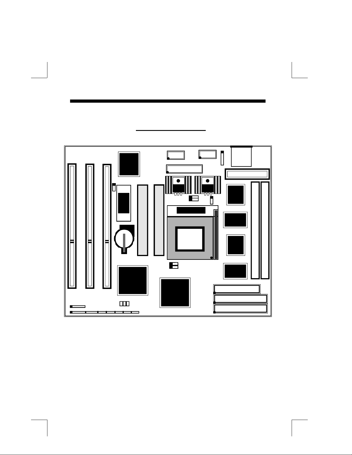
TheP55-KV utilizesVIA82C580VPXPCIsetchipset to supportIntelPentium
Processor PCI/ISA system. The VIA 82C580VPX PCIset chipset consists of one
82C585VPXsystemcontroller(TSC),two82C587VPDataPath(TDP)devices,and
one82C586APCIISA/IDE Acceleratorbridgechip.Itprovides aninterfacewhich
translates CPU cycle into PCI bus cycle and PCI burst read/write capability. In
addition, it provides high performance PCI arbitor to support two PCI Masters,
RotatingPriorityMechanism,andHiddenArbitrationSchemeMinimizesArbitration
Overhead.
Therearefourinterruptsin eachPCIslot:INTA#,INTB#, INTC#,andINTD#.Since
the P55-KV adapts the PCI auto-configuration with the system BIOS Setup utility.
When the system is turned on after adding a PCI add-in card, the BIOS automatically
configure interrupts, DMA channels, I/O space, and other paramaters. You do not
have to configure jumpers or worry potential resource conflicts. Because PCI cards
use the same interrupt resource as ISA cards, you must specify the interrupt used by
ISA add-in cards in the BIOS Setup utility.
However, if a "Legacy card" (such as plug paddle card and cable into the ISA slot.)
ispluggedinthesystem,thefollowingmodificationsintheROMSETUPUTILITY
becomenecessary.First,youmustenter PCICONFIGURATIONSETUPutilityfrom
ROMSETUPUTILITYmainmenutosetthe"PCIIDEIRQMAPTO:ISA".
Then,youmustenterCHIPSETFEATURESSETUPUTILITYfromROMSETUP
UTILITYmainmenuandsetthe"OnboardPrimaryPCIIDE:DisabledandOnboard
SecondaryPCIIDE:Disabled."WhenyouplugthePCI/ISAIDEcardintothe
system,Youshould DisableOnboardPrimaryandSecondaryPCIIDEfrom
CHIPSETFEATURESSETUPUTILITYtoo.
you can set the system interrupt request (IRQ) on some "Legacy cards" which have
no paddle card and cable (refer to user's manual of the card) to a proper system IRQ
level (In general, the card's Primary is assigned to INTA and Secondary is assigned
to INTB). If the card is plugged into slot 1(marked PCI#1), you cannot use second
slot (marked PCI#2) because the Secondary INT signal takes INTB from the slot
(refertoPage3-12forcircuitdiagram).TheuserthenentersPCICONFIGURATION
SETUPutilityfromROMSETUPUTILITYmainmenuandsetsthe"PCIIDEIRQ
MAP TO :PCI-Slot 1" (depend on the slot # where the Legacy card is plugged).
.
R

AWARD BIOS 3-1
CHAPTER 3
AWARD BIOS SETUP
Award'sROMBIOSprovidesabuilt-inSetupprogramwhichallowsusertomodifythe
basicsystemconfigurationandhardware parameters. The modified data will be stored
inabattery-backedCMOSRAMsodatawillberetainedevenwhenthepoweristurned
off.Ingeneral,theinformationsavedintheCMOSRAMstaysunchangedunlessthere
isa configuration change in the system, such as a hard drive replacement or a device is
added.
ItispossiblefortheCMOS batterytofail,thiswillcausedataloseinCMOSonly.Ifthis
does happen you will need to reconfigure your configuration parameter.
To enter Setup Propgram
Poweronthecomputerandpress<Del>keyimmediately,thiswillbringyouintoBIOS
CMOSSETUPUTILITY.
ROMPCI/ISABIOS(2A5LDPAD)
CMOSSETUPUTILITY
AWARDSOFTWARE,INC.
STANDARD CMOS SETUP SUPERVISOR PASSWORD
BIOS FEATURES SETUP USER PASSWORD
CHIPSET FEATURES SETUP IDE HDD AUTO DETECTION
POWER MANAGEMENT SETUP HDD LOW LEVEL FORMAT
PNP/PCI CONFIGURATION SAVE & EXIT SETUP
INTEGRATED PERIPHERALS EXIT WITHOUT SAVING
LOAD SETUP DEFAULTS
ESC : QUIT : SELECT ITEM
F10 : Save & Exit Setup (Shift)F2 : Change Color
Time, Date, Hard Disk Type...
Figure 3-1 CMOS SETUP UTILITY
The menu displays all the major selection items. Select the item you need to
reconfigure. The selection is made by moving cursor (press any direction key ) to the
item and press the 'Enter' key. An on-line help message is displayed at the bottom of
the screen as the cursor is moving to various items which provides a better under-
standing of each function. When a selection is made, the menu of selected item will
appear so the user can modify associated configuration parameters.

3-2 CHAPTER 3
3-1 STANDARD CMOS SETUP
Choose "STANDARD CMOS SETUP" in the CMOS SETUP UTILITY Menu
(Fig.3-1). The STANDARD CMOS SETUP allows user to configure system setting
suchasthecurrent dateandtime,typeofhard diskdriveinstalledfloppydrivetype, and
displaytype. Memorysizeisauto-detectedbytheBIOSanddisplayedforyourreference.
Whenafieldishighlighted(usedirectionkeystomovecursorand<Enter>keytoselect),
theentriesin the field will be changed bypressing <PgDn> or <PgUp> keys or usercan
enter new data directly from the keyboard.
Figure 3-2 STANDARD CMOS SETUP
Selecting the "BIOS FEATURES SETUP" option in the CMOS SETUP UTILITY
menu allows user to change system related parameters in the displayed menu. This
menu shows all of the manufacturer's default values of P55-KV. Again, user can move
the cursor by pressing direction keys and <PgDn> or <PgUp> keys to modify the
parameters. Pressing [F1] key to display help message of the selected item.
This setup program also provides 2 convinent ways to load the default parameter data
fromBIOS[F6]orCMOS[F7]areaifshowndata iscorrupted.Thisprovides thesystem
a capability to recover from any possible error.
3-2 BIOS FEATURES SETUP
NOTE: The "Halt On :" field is to determine when to halt the system by the BIOS if error
occurrs.
NOTE: If hard disk Primary Master/Slave and Secondary Master/Slave are set "Auto",
then the hard disk size and model will be auto-detected.
ROM PCI/ISA BIOS(2A5LDPAD)
STANDARD CMOS SETUP
AWARD SOFTWARE, INC.
ESC : Quit : Select Item PU/PD/+/- : Modify
F1 : Help (Shift) F2 : Change Color
Date (mm:dd:yy) : Wed, Apr 17 1996
Time (hh:mm:ss) : 14 : 30 : 50
HARD DISKS TYPE SIZE CYLS HEAD PRECOMP LANDZONE SECTORS MODE
Primary Master :Auto 0 00 0 0 0 Auto
Primary Slave :Auto 0 00 0 0 0 Auto
Secondary Master : Auto 0 00 0 0 0 Auto
Secondary Slave : Auto 0 00 0 0 0 Auto
Drive A : 1.44M,3.5 in.
Drive B : None
Floppy 3 mode Support:Disable
Video : EGA/VGA
Halt On : All Errors
Base Memory : 640K
Extended Memory: 15360K
Other Memory : 384K
Total Memory : 16384K

AWARD BIOS 3-3
Note: The Security Option contians "setup" and "system". The "setup" indicates
that the password setting is for CMOS only while the "system" indicates the
password setting is for both CMOS and system boot up.
CPU Internal Cache / External Cache:These two categories speed up memory
access. However, it depends on CPU/chipset design. The default value is Enable.
If your CPU is without Internal Cache then this item "CPU Internal Cache" will not
be shown.
Enabled:Enable cache.
Disable : Disable cache.
Virus Warning: This category flashes on the screen. During and after the system
boots up, any attempt to write to the boot sector or partition table of the hard disk
drive will halt the system and an error message will appear. You should then run an
anti-virus program to locate the virus. Keep in mind that this feature protects only the
boot sector, not the entire hard drive. Default value is Disabled
Enabled : Activates automatically when the system boots up causing a warning
message to appear when any attempt to access the boot sector or
harddiskpartitiontable.
Disabled:No warning message to appear when any attempt to access the boot
sector or hard disk partition table.
ROM PCI/ISA BIOS(2A5LDPAD)
BIOS FEATURES SETUP
AWARD SOFTWARE, INC.
Esc : Quit : Select Item
F1 : Help PU/PD/+/- : Modify
F5 : Old Values (Shift)F2 : Color
F7 : Load Setup Defaults
Figure 3-3 BIOS FEATURES SETUP
Virus Warning :Disabled Video BIOS Shadow :Enabled
CPU Internal Cache : Enabled C8000-CBFFF Shadow :Disabled
External Cache : Enabled CC000-CFFFF Shadow :Disabled
Boot Sequence : A, C D0000-D3FFF Shadow :Disabled
Swap Floppy Drive : Disabled D4000-D7FFF Shadow :Disabled
Boot Up Floppy Seek : Enabled D8000-DBFFF Shadow :Disabled
Boot Up NumLock Status : On DC000-DFFFF Shadow :Disabled
Boot Up System Speed : High
IDE HDD Block Mode : Enabled
Gate a20 Option : Fast
Memory Parity Check : Disabled
Typematic Rate Setting : Disabled
Typematic Rate (Chars/Sec) : 6
Type matic Delay (Msec) : 250
Security Option : Setup
IDE Second Channel Control : Enabled
PCI/VGA Palette Snoop : Disabled
OS Select For DRAM > 64MB : Non-OS2

3-4 CHAPTER 3
Quick Power On Self Test:This category speeds up Power On Self Test (POST)
after you power on the computer. If it is set to Enable, BIOS will shorten or skip
some check items during POST.
Enabled : Enable quick POST.
Disabled: Normal POST.
BootSequence:This categorydetermines which drive is searched first for
theO/S(OperatingSystem).DefaultvalueisA,C.
A,C :System will search for floppy disk drive first then hard disk drive.
C,A :System will search for hard disk drive first then floppy disk drive.
Swap Floppy Drive:ThiswillswapyourphysicaldrivelettersA&Bif youareusing
two floppy disks. Default value is Disabled.
Enabled :Floppy A & B will be swapped under the O/S.
Disabled :Floppy A & B will be not swapped.
BootUpFloppySeek:DuringPower-On-Self-Test(POST),BIOSwilldetermineifthe
floppydiskdriveinstalledis40or80tracks.Only360Ktypeis40trackswhile 760K,
1.2Mand1.44Mareall80tracks.ThedefaultvalueisEnabled.
Enabled :BIOS searches for floppy disk drive to determine if it is 40 or 80 tracks.
NotethatBIOScannottellfrom 720K, 1.2M or 1.44M drive type as they are
all80tracks.
Disabled: BIOS will not search for the type of floppy disk drive by track number.
Note that there will not be any warning message if the drive installed
is 360K.
Boot Up NumLock Status: The default value is On.
On : Keypad is number keys.
Off : Keypad is arrow keys.
BootUP System Speed: Select default system speed. The system will run at the
selected speed after the system boots.
High: Set the speed to high.
Low : Set the speed to low.
Gate A20 Option:This refers to the way the system addresses memory above 1MB
(extendedmemory).ThedefaultvalueisFast.
Normal: The A20 signal is controlled by keyboard controller or chipset hardware.
Fast : The A20 signal is controlled by Port 92 or chipset specific method.

AWARD BIOS 3-5
Typematic Rate Setting: This determines the typematic rate.
Enabled : Enable typematic rate and typematic delay programming.
Disabled: Disable typematic rate and typematic delay programming. The system
BIOS will use default value of this 2 items and the default is controlled
by keyboard.
Typematic Rate(Chars/Sec):
6 : 6 characters per second. 8 : 8 characters per second.
10: 10 characters per second. 12: 12 characters per second.
15: 15 characters per second. 20: 20 characters per second.
24: 24 characters per second. 30: 30 characters per second.
Typematic Delay(Msec): When holding a key, the time between the first and
second character displayed.
250 : 250msec.
500 : 500 msec.
750 : 750 msec.
1000: 1000 msec.
Security Option: This category allows you to limit access to the system and Setup,
or just to Setup. The default value is Setup.
System:The system will not boot and the access to Setup will be denied if the
correct password is not entered at the prompt.
Setup : The system will boot, but the access to Setup will be denied if the correct
password is not entered at the prompt.
PCI/VGA Palette Snoop: This filed controls the ability of a primary PCI VGA
controller to share a common palette(When a snoop write cycles) with an ISA
video card. The default value is Disabled.
Enabled: If an ISA card connects to a PCI VGA card via the VESA connector
and the ISA card connects to VGA monitor and uses the RAMDAC of
PCIcard,thePCI/VGAPaletteSnoopisenabled.
Disabled: Disable the VGA card Palette snoop function.
VideoBIOSShadow:ItdetermineswhethervideoBIOSwillbecopiedtoRAM,
however it is optional from chipset design. Video Shadow will increase the video
speed.
Enabled :Video shadow is enabled.
Disabled:Video shadow is disabled.

3-6 CHAPTER 3
3-3 CHIPSET FEATURES SETUP
Choose the "CHIPSET FEATURES SETUP"in the CMOS SETUP UTILITY
menu to display the following menu.
ROM PCI/ISA BIOS(2A5LDPAD)
CHIPSET FEATURES SETUP
AWARD SOFTWARE, INC.
C8000 - CBFFF Shadow :
CC000 - CFFFF Shadow:
D0000 - D3FFF Shadow:
D4000 - D7FFF Shadow:
D8000 - DBFFF Shadow:
DC000 - DFFFF Shadow:
These categories determine whether optional ROM will be copied to RAM by 16K
byte or 32K byte per/unit and the size depends on chipset.
Enabled : Optional shadow is enabled.
Disabled: Optional shadow is disabled.
Auto Configuration : 70 ns
Video BIOS Cacheable : Enabled
System BIOS Cacheable : Disabled
Memory Hole At 15Mb Addr. : Disabled
Sustained 3T Write : Disabled
PBSRAM : 3-1-1-1
Read Pipeline : Enabled
Write Pipeline : Enabled
DRAM Timing Control : Auto
Reduce DRAM leadoff cycle : Disabled
Esc : Quit : Select Item
F1 : Help PU/PD/+/- : Modify
F5 : Old Values (Shift)F2 : Color
F7 : Load Setup Defaults
Note:When you insert slower memery modules in the system and set a faster
timing,maybethesystemwillhangup.
Figure 3-4 CHIPSET FEATURES SETUP

AWARD BIOS 3-7
DRAM Timing: The default value is 60ns.
60ns :2 (faster) Burst Wait State, for 60~70ns Fast Page Mode/EDO DRAM.
70ns : 3 (slower) Burst Wait State, for 70ns Fast Page Mode/EDO DRAM.
Video BIOS Cacheable: The default value is Enabled.
Enabled :Enabled the Video BIOS Cacheable to speed up the VGA
Performance.
Disabled: Disabled the Video BIOS Cacheable function.
Memory Hole at 15M-16M: The default value is Disabled.
Disabled:Normal Setting.
Enabled : This field enableds the main memory (15~16MB) remap to ISA BUS.

3-8 CHAPTER 3
3-4 POWER MANAGEMENT SETUP
Choose the "POWER MANAGEMENT SETUP" in the CMOS SETUP
UTILITYtodisplaythefollowingscreen.Thismenuallowstheusertomodifythe
power management parameters and IRQ signals. In general, these parameters
should not be changed unless it is absolutely necessary.
Figure 3-5 POWER MANAGEMENT SETUP
ROM PCI/ISA BIOS
POWER MANAGEMENT SETUP
AWARD SOFTWARE, INC.
Again, user can move the cursor by pressing direction keys to the field needed to be
modified and press <PgDn> or <PgUp> to alter item selection. You can only change
the content of Doze Mode, Standby Mode, and Suspend Mode when the Power
Management is set to 'User Define'.
3-4-1 The Description of the Power Management
A. PowerManagementmodeselection:
Disabled :ThesystemoperatesinNORMALconditions(Non-GREEN)
and the Power Management function is disabled.
Max.saving: This mode will maximize the power saving capability.
Min.saving: This mode will minimize the power saving capability.
Userdefine: Allowusertodefinetimeoutparameterstocontrolpowersavingmode.
Refer to item B shown below.
Esc : Quit : Select Item
F1 : Help PU/PD/+/- : Modify
F5 : Old Values (Shift)F2 : Color
F7 : Load Setup Defaults
Power Management : User Define ** Power Down & Resume Events **
PM Control by APM : Yes IRQ5 (LPT 2) : Primary
Video off Option : Suspend -> Off IRQ6 (Floppy Disk) : Primary
Video off Method : V/H SYNC+Blank IRQ7 (LPT 1) : Primary
Conserve Mode : Disabled IRQ8 (RTC Alarm) : Disabled
Modem Use IRO : 3 IRQ9 (IRQ2 Redir) : Secondary
** PM Timers ** IRQ10 (Reserved) : Secondary
HDD Power Down : 15 Min IRQ12 (PS/2 Mouse) : Primary
Doze Mode : 4 Min IRQ13 (Coprocessor) : Disabled
Suspend Mode : 10 Min IRQ14 (Hard Disk) : Primary
IRQ15 (Reserved0 : Primary
** PM Events **
VGA : ON
LPT & COM : LPT /COM
HDD & FDD : ON
DMA /master : OFF
Primary INTR : ON
IRQ3 (COM 2) : Primary
IRQ4 (COM 1) : Primary

AWARD BIOS 3-9
B. Time-outparameters:
HDDStandby
HDDStandbytimercan be set from 1 to 15 minute(s).
System Doze
The "System Doze" mode timer starts to count when there is no "PM events"
occurred. The valid time-out setting is from 1 minute up to 1 hour.
System Suspend
This function works only when the Pentium Procssor is installed. The timer starts
to count when "System Standby" mode timer is timed out and no "PM Events"
occurred. Valid range is from 1 minute up to 1 hour.
3-4-2 Description of the Green Functions
The P55-KV supports HDD Power Down, Doze & Suspend power saving functions.
In addition, the hardware suspend function is supported when the J11-SLEEP (Refer
to Figure1-1) is closed to enter the Suspend function.
The detailed description of these functions is provided in the next page.
HDD Standby Mode
When system stop reading or wiriting HDD, the timer starts to count. The system will
cut off the HDD power when timer runs out of time. The system will not resume
operation until either a read from or a wirte to HDD command is executed again.
Doze Mode
The system hardware will drop down CPU clock from nomal working speed
when Doze mode time-out occurs.
Suspend Mode
When the system suspend timer times out, the system will enter the suspend mode
andthe chipset will stop CPU clock immediately. The power consumption in
Suspend Mode is lower than in standby mode. The screen is also blanked out.

3-10 CHAPTER 3
PM Events:
AWARDBIOSdefines 15 PM Events in the power managementmode(Doze &
suspend). The user can initialize any PM Events to be "Enable" or "Disable".
When the system detects all of the enabled events, do not have any activity. It will
start the system Doze timer first if the "Power Management" is not "Disabled". Once
the system Doze timer is timed out, it will process doze power saving procedure
bystartingthesystemsuspendtimer.Whenthesuspendtimertimesout,alloftheCPU
clock will stop by dropping system clock down to zero and remains this way
until any one of the "Enabled" event occurrs.
3-5 PNP/PCI CONFIGURATION
The PNP/PCI configuration program is for the user to modify the PCI/ISA IRQ signals
when various PCI/ISA cards are inserted in the PCI or ISA slots.
WARNING : Any misplacing IRQ could cause system can't pick out the rescouces.
ROM PCI/ISA BIOS(2A5LDPAD)
PNP/PCI CONFIGURATION
AWARD SOFTWARE, INC.
Figure 3-6 PCI CONFIGURATION SETUP
ESC : Quit : Select Item
F1 : Help PU/PD/+/- : Modify
F5 : No Change (Shift) F2 : Color
F7 : Load Setup Defaults
Resources Controlled By : Manual CPU to PCI Write Buffer : Enabled
Reset Configuration Data : Disabled PCI Dynamic Bursting : Enabled
PCI Master 0 WS Write : Enabled
IRQ-3 assigned to : Legacy ISA Quick Frame Generation : Enabled
IRQ-4 assigned to : Legacy ISA PCI Arbitration Mode : Req-Base
IRQ-5 assigned to : PCI/ISA PnP
IRQ-7 assigned to : Legacy ISA PCI IRQ Actived By : Level
IRQ-9 assigned to : PCI/ISA PnP PCI IDE IRQ Map To : PCI-AUTO
IRQ-10 assigned to : PCI/ISA PnP Primary IDE INT# : A
IRQ-11 assigned to : PCI/ISA PnP Secondary IDE INT# : B
IRQ-12 assigned to : PCI/ISA PnP
IRQ-14 assigned to : Legacy ISA
IRQ-15 assigned to : Legacy ISA
DMA-0 assigned to : PCI/ISA PnP
DMA-1 assigned to : PCI/ISA PnP
DMA-3 assigned to : PCI/ISA PnP
DMA-5 assigned to : PCI/ISA PnP
DMA-6 assigned to : PCI/ISA PnP
DMA-7 assigned to : PCI/ISA PnP

AWARD BIOS 3-11
Resource Controlled By:The default value is Manual.
Manual:The field defines that the PNP Card's resource is controlled by manual.
You can set which IRQ-X and DMA-X assigned to PCI/ISA PNP or
Legacy ISA Cards.
Auto: If your ISA card and PCI card are all PNP cards. To set this field Auto.
The BIOS will be assigned the interrupt resource automatically.
Reset Configuration Data:The default value is Disabled
Disabled:Normal Setting
Enabled:If you plug some Legacuy cards in the system and there is record into
ESCD(ExtendedSystemConfigurationData).Youcansetthisfieldto
Enable and to clear ESCD at one time, when some Legacy cards are removed.
PCI IDE IRQ Map To:The default value is PCI-AUTO
When you have true PCI card(s) plugged into the system, you will not need
to change any thing here in the SETUP program. However, if you do not
know whether you have true PCI card or not, please refer to your PCI card
user's manual for the details.
When you have a Legacy card (describbed in section 2-5) to be plugged
into the system,a proper setting is extremely important or it may cause the
system hung up. The diagram shown below tells you how the Rotating
Priority Mechanism is designed.
Figure 3-7 The Combination of PCI INT# lines
PCI
Chipset
INTA
INTD
PCI#1PCI#2 INTA
INTD
INTD
INTC
INTB
INTBINTA
INTC
INTCINTB
Table of contents
Other EPOX Motherboard manuals