Epple Maschinen SBS 32 400 V User manual

26.01.07, SBS 32, Drills Page 1 from 33
User manual
Drill SBS 32 400 V
Keep for future reference!

26.01.07, SBS 32, Drills Page 2 from 33
Table of contents
1SAFETY.............................................................................................................. 5
1.1 Safety notes (warning notes).............................................................................6
1.1.1 Classification of hazards........................................................................... 6
1.1.2 More, used pictograms.............................................................................. 7
1.2 Proper use...........................................................................................................7
1.3 Danger, which can emanate from drill ..............................................................8
1.4 Qualification of personnel..................................................................................9
1.4.1 Target group............................................................................................... 9
1.4.2 Authorised personnel................................................................................ 9
1.4.3 The operator must.....................................................................................10
1.4.4 The user must ...........................................................................................10
1.4.5 Special claims to the qualification...........................................................11
1.5 Operator position..............................................................................................11
1.6 Safety equipment..............................................................................................11
1.6.1 Main switch lockable ................................................................................12
1.6.2 Chip protection .........................................................................................12
1.6.3 Safe belt cover ..........................................................................................12
1.6.4 Prohibition, instruction and warning signs.............................................12
1.7 Safety check at the machine............................................................................13
1.8 Personal protective equipment for special work............................................14
1.9 Safety during the use of the machine .............................................................15
1.10 Safety during general maintenance work .......................................................16
1.10.1 Breaking and assuring the machine........................................................16
1.10.2 Use of hoisting devices for attendance work..........................................16
1.10.3 Mechanic attendance work at the machine.............................................17
1.11 Accident report.................................................................................................17
1.12 Electricity ..........................................................................................................17
2TECHNICAL DATA .......................................................................................... 18
2.1 Electrical connection data ...............................................................................18
2.2 Machine data.....................................................................................................18
2.3 Dimensions.......................................................................................................18
2.4 Necessary working room .................................................................................18
2.5 Environmental conditions................................................................................18
2.6 Emissions..........................................................................................................18
3ASSEMBLY...................................................................................................... 19
3.1 Delivery volume................................................................................................19
3.2 Transport...........................................................................................................19
3.3 Storage..............................................................................................................19
3.4 Positioning and assembly................................................................................20
3.4.1 Claims to installation location..................................................................20
3.4.2 Assembly...................................................................................................20

26.01.07, SBS 32, Drills Page 3 from 33
3.4.3 Anchor - free assembly ............................................................................20
3.4.4 Anchor free assembly...............................................................................20
3.4.5 Positioning ................................................................................................20
3.5 First initiation....................................................................................................21
3.5.1 Cleaning.....................................................................................................21
3.5.2 Sight check/ mnaual function check........................................................21
3.5.3 Electrical connection................................................................................21
3.5.4 Function check..........................................................................................21
4HANDLING....................................................................................................... 22
4.1 Safety.................................................................................................................22
4.2 Control and inidcator elements .......................................................................23
4.2.1 Control elements electrical ......................................................................23
4.2.2 Control elements mechanical ..................................................................23
4.3 Activating the machine.....................................................................................24
4.3.1 Release EMERGENCY STOP control.......................................................24
4.3.2 Main switch ...............................................................................................24
4.3.3 Turning direction choice ..........................................................................24
4.3.4 Driving speed choice................................................................................24
4.3.5 Close chip protection ...............................................................................24
4.3.6 Close belt cover ........................................................................................24
4.3.7 Activating ..................................................................................................25
4.3.8 Deactivating...............................................................................................25
4.4 Hand drive.........................................................................................................25
4.5 Adjust depth arrester........................................................................................25
4.6 Table height adjustment...................................................................................25
4.7 Turn, swivel, tilt table .......................................................................................25
4.8 Machine light.....................................................................................................25
4.9 Centre sleeve fetching......................................................................................26
4.10 Working notes...................................................................................................26
4.10.1 General notes............................................................................................26
4.10.2 Fixing the work part in the vice................................................................26
4.10.3 Eject a tool.................................................................................................26
5MAINTENANCE ............................................................................................... 27
5.1 Safety.................................................................................................................27
5.1.1 Preparation................................................................................................27
5.1.2 Recommissioning.....................................................................................27
5.2 Inspection and attendance...............................................................................28
5.2.1 Daily work..................................................................................................28
5.2.2 Weekly work..............................................................................................28
5.2.3 Monthly work.............................................................................................28
5.2.4 Semi –yearly work....................................................................................28
5.3 Maintenance......................................................................................................28
6FAILURES........................................................................................................ 29
7APPENDIX........................................................................................................ 30


26.01.07, SBS 32, Drills Page 5 from 33
1 Safety
Glossary of symbols
Symbol
account
Reference to another
page
Calls on you to get in
action
enumerations
This first part of the operating manual:
Explains the meaning and use of the warning references contained in the
operating manual
Highlights the dangers that might arise for you and others if these instructions are
not followed
Explains how to use the machine properly
Tells you how to avoid dangers
In addition to this operating manual please observe:
Legal regulations for accident prevention
Applicable laws and regulations
The prohibition, warning and mandatory lables as well as the warning notes
You are liable to follow the european norms by installation, operation, maintenance and
reparation of the machine.
If european norms still are outstanding you are liable to use the country –specific
effectual norms.
If necessary you have to take some in –company actions before the use of the machine
to follow the country –specific instructions.
Always keep this document close to the machine.
Support / Information
If you are unable to solve a problem using this manual, please contact us for advice:
Epple Maschinen GmbH
Service und Support
Auf der Breite 2-14
D-73349 Wiesensteig
26.01.07, SBS 32, Drills Page 6 from 33
1.1 Safety notes (warning notes)
1.1.1 Classification of hazards
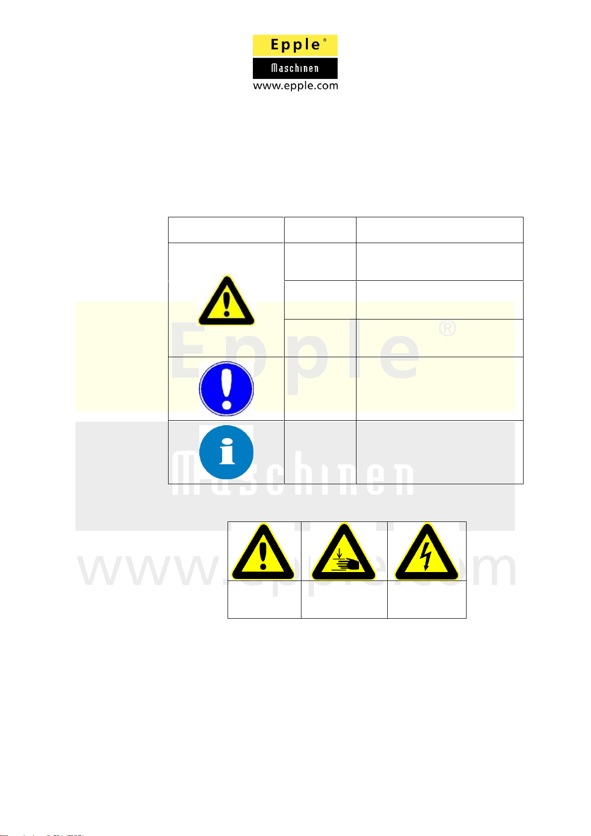
We classify the safety warnings into various levels. The table below
gives an overview of the classification on symbols (pictograms) and
warning labels fort he specific danger and is (possible) consequences.
Symbol
Warning
alert
Definition/ Consequences
Danger!
Imminent danger that will cause
serious injury or death to
personnel.
Warning!
Risk: a danger that might cause
serious injury of death to
personnel.
Caution!
Risk: a danger that might cause
serious injury of death to
personnel.
Attention!
Situation that could cause
damage to the machine or
products and other types of
damage. No risk of injury
personnel.
Information!
Application tips and other
important or useful information
and notes. No dangerous or
harmful consequences for
personal or objects.
In case of specific dangers, we replace the pictogram by
General
danger
Injuries to hand
Dangerous,
electrical
tension

26.01.07, SBS 32, Drills Page 7 from 33
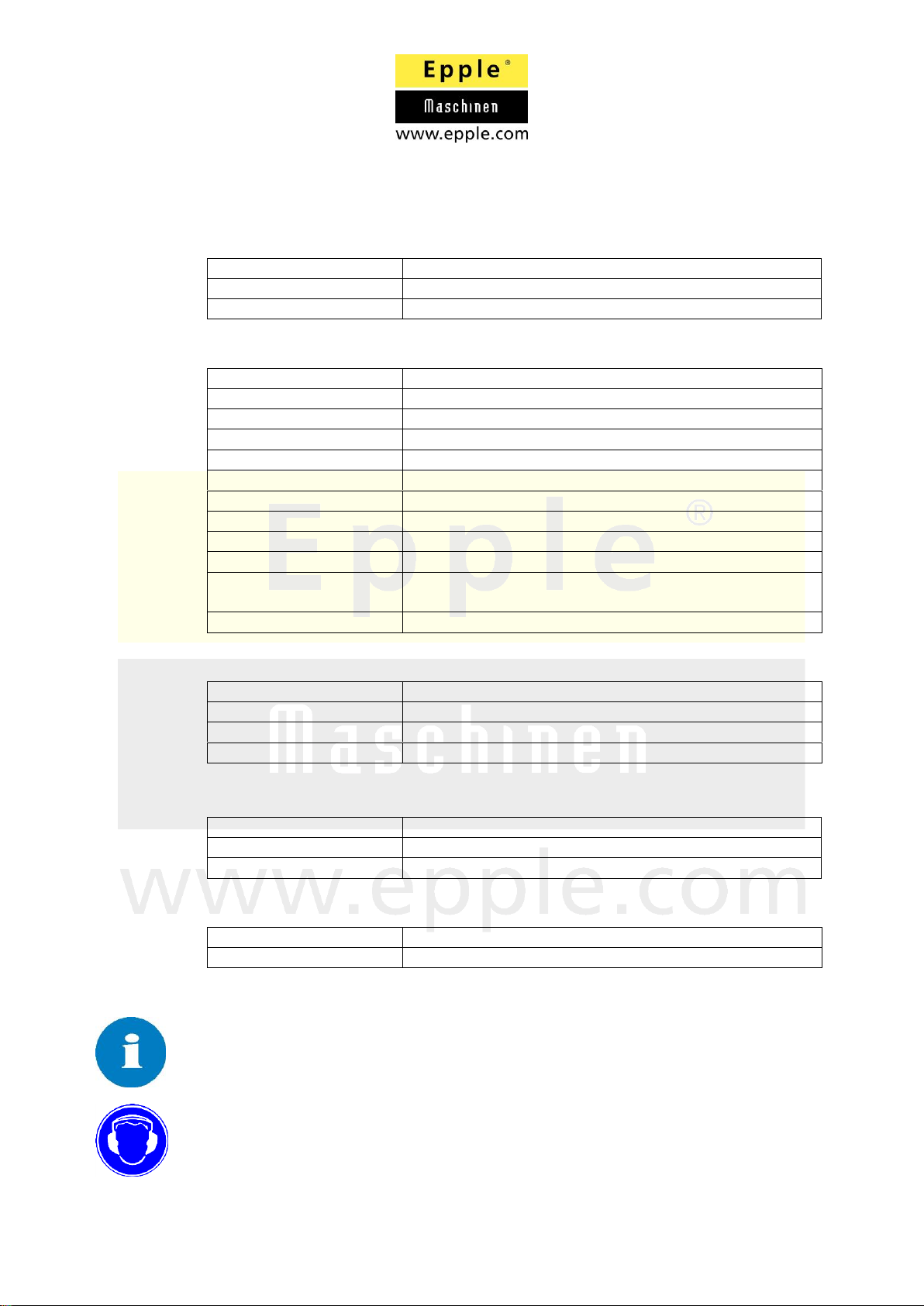
1.1.2 More, used pictograms
Engaging
forbidden
Draft mains
plug
Wear
protection
gloves
Wear
protection
glasses
Wear ear
protection
Wear
protective
suit
Wear safety
shoes
Mind the
environment
Your contact
person
1.2 Bestimmungsgemässe Verwendung der Maschine
Warning!
In the event of improper use, the machine
Will endanger employees,
Will endanger the machine and other material property of the operator,
may affect proper operation of the machine
The machine may not be in an explosive environment.
The machine was built and construed for the following utilisations
This drill only is for working with metal, wood and plastic.
Working with flammable materials is forbidden.
Any other use is improper.
The use and positioning of the machine only is allowed in dry and well aired
rooms
If the machine is used in any way other than as described above, modified
without authorisation of Epple Maschinen GmbH or operated with different
process data, then it is being used improperly.
We do not take any liabilities for damage caused by improper use. We would like
to point out that any modifications to the construction, or technical or
technological modifications that have not been authorised by Epple Maschinen
GmbH will also render the guarantee null and void.
It is also part of proper use that
For an optimal efficiency, you have to observe the following:
The correct choice of the tool, according to the material

26.01.07, SBS 32, Drills Page 8 from 33
The correct clamping of the tool
The correct clamping of the work part
The correct cutting pressure and cutting speed
The adequate coolant lubricant
Warning!
An improper use can lead to heaviest injuries.
The rebuilding or the change of the performance data is forbidden and
endangers personnel and machine.
1.3 Danger, which can emanate from drill
Construction and building of the machine equate to level of technique. The
machine was checked of operating safety.
However there exist risks and dangers by the use:
Improper use and non –observance of safety instructions can cause
extensive injuries like bruises, crops, fractures or separation of members
Risk of injury by kickback or derailing of work parts and/ or tool
Danger of electric shock by damaged and electric units
Risk of stumbling by about lying work parts or work part rests
A cant of work parts can cause heavy injuries
Danger for ears by loud noise (from 85 dB(A))
The running drill can capture work wear or long hair insert
Danger of cutting by arris work parts
Danger of accidents by damaged tool (f. e. stump, loose, chapped etc.)
During use of coolant lubricant exists the danger of skin diseases
By the maintenance and use of the machine dangers because of false use or
improper maintenance may encounter you.
Information
To avoid errors and dangers, all users who are assigned with the
assembly, the use and maintenance have to be qualified and read plus
understand the operating manual.
By improper use of the machine may:
Danger for body and life exist
The machine and other property can be endangered
The safe function of the machine can be affected
It is very important that you disconnect the machine for cleaning and maintenance
work.
Warning!
The machine only can be used with functioning safety equipment. The machine
must be disconnected directly if you notice damaged or failure safety equipment.
All special units that are mounted from the operator have to include the
accordant safety units. You are not allowed to derogate or avoid the safety units
of machine. The responsibility therefore is the operators.

26.01.07, SBS 32, Drills Page 9 from 33
1.4 Qualification of personnel
1.4.1 Target group
This manual is addressed to the operators, users and maintenance staff.
The warning notes therefore refer to both operation and maintenance of
the machine.
Determine clearly and irrevocably who will be responsible for the
different activities on the machine (operation, maintenance and repair).
1.4.2 Authorised personnel
Warning!
Incorrect use and maintenance of the machine constitutes a danger for
personnel, objects and environment.
Only authorized personnel may operate the machine.
Authorised personnel for the use and maintenance are:
Trained and instructed operators
Trained and instructed experts of the retaile

26.01.07, SBS 32, Drills Page 10 from 33
1.4.3 The operator must
The operator is bound to instruct the personnel in regular intervals (at
least once a year) on
Monitoring all safety standards that apply to the machine
Maintaining the operation
Obtaining accredited technical guide lines
Furthermore the operator is bound to:
Document training/ instructions
Require the staff to confirm participation in training/ instruction by
means of a signature
Control whether the personnel observes the operation manual
and whether it is close to the machine
Check that the staff is aware of safety and dangers in the
workplace and that they observe the operating manual
1.4.4 The user must
Observe commands of superiors and sentinels
Do not remove safety equipment during work
Avoid contact with tool
Use personal protective equipment (incl. Skin protection)
Wear close work wear
Remove chips with equipment and not by hand
Do not use damaged thread, wood, HSS drills
Work parts have to be clamped safe and feast
Assure order and cleanness at the work place
Never work with damaged machine parts
Announce defects directly to your superior
Read and understood the user manual
To be familiar with all safety regulations and safety arrangements
Use the machine

26.01.07, SBS 32, Drills Page 11 from 33
1.4.5 Special claims to the qualification
For the work with electric units or operating materials more claims to the
qualification are efficient.
Only electronic experts are allowed to do work at electric units. If the
instruct and oversee you, you are allowed, too.
Before you accomplish work at electric units or operating material you
have to keep the following instructions in this order:
Disconnection
Assure against resetting
The unit must be de - energized
Please observe the effective regulations of the insurance association
and the accident prevention.
1.5 Operator position
The operator position is straight standing in front of the profile roll. Every other
position can lead to danger of personnel.
1.6 Safety equipment
The use of the machine is only allowed with correct functioning safety devices.
The machine is to decommission directly if a safety device is deficient or
effectless. Therefore you are responsible as an operator/ user. After response,
defect or falling out of a safety device, the profile roll may not be in use until:
The failure/ cause of the failure is abolished
You have checked the machine and fell confident that there is no danger
for personnel or property values
Warning!
If you remove the destined safety devices or abrogate them by bridging you
endanger yourself and other personnel working at the machine.
Consequences can be heavy injuries until death.
The drill includes the following safety devices:
Main switch lockable with EMERGENCY STOP function
Chip protection
Belt protection cover with safety switch

26.01.07, SBS 32, Drills Page 12 from 33
1.6.1 Main switch lockable
At the front side of the machine is a lockable
switch with an optional u –lock.
Release a used emergency Stop control
by pushing the button in direction of
arrow to jump out of the catch
mechanism to let it open and
consequently it is possible to activate
the machine again.
1.6.2 Chip protection
You can fold up the chip protection. Additionally the
chip protection is height adjustable. Springs keep it
in its particular position. The chip protection has no
control function. During drilling you have to click the
chip protection in front of the tool.
1.6.3 Safe belt cover
The safe belt cover has a safety switch. In opened position the current entry to the motor
is break.
1.6.4 Prohibition, instruction and warning signs
Observe additionally to the user manual the safety and warning notes at the
machine. Warning notes that only are to find in the user manual and not at the
machine have additionally absolute validation and are to observe implicitly.

26.01.07, SBS 32, Drills Page 13 from 33
1.7 Safety check at the machine
You are bound to check the machine at least once pro shift. Announce scarcities
and defects directly. You have to check alle arrangements
Before every shift
By disconnected use before every use
After every maintenance
Check that all warning notes and signs are complete and good readable at the
machine.
Document your security check in an adequate way.
Checking in general
Safety equipment
Operation
OK
Chip protection
Fixed mounted, flap smooth
Safety notes
All safety notes are located and undamaged at
the machine
Function check of the safety elements
Element
Operation
OK
EMERGENCY
STOP control
Stop the machine directly after use of the
emergency Stop control.
Belt protection
cover
If you open the belt cover the motor
disconnects or rather the motor does not start
with opened cover.

26.01.07, SBS 32, Drills Page 14 from 33
1.8 Personal protective equipment for special work
Use for your work always the necessary personal protective.
Protect your face and your ears: Wear a safety helmet with a face guard for
every work, especially for any kind of work where your face and eyes are
exposed to hazards.
Use protective gloves when lifting or handling pieces with sharp edges.
CAUTION!
Do not wear protective gloves, if you have to hold work parts with the hands.
Hooking work parts can cause heaviest injuries that can lead to constrictions and/
or breaks.
Wear safety shoes when fitting, dismanteling or transporting heavy components.
Use ear protection over 80dB
Wear closely safety suit.
Do not wear long hair open, wear hairnet or cap
Check before start of work whether the required protective is complete and intact.
Broken protective has to be modernized. Always announce missing protective
and only begin to work if the protective is complete.
CAUTION!
Contaminated, defiled protectives can release indispositions. Clear them up after
every use and at least once a week.

26.01.07, SBS 32, Drills Page 15 from 33
1.9 Safety during the use of the machine
Warning!
Assure before activating the machine that no person or property value is
endangered.
Do not accomplish work at the machine that is dangerous:
Assure that other people are not endangered by you
Observe the maximum drilling cap of the machine
Clamp the work parts before connection correct and feast
Do not try to break the run –down drill chuck with the hand
Always break the machine for control measures at the work part
Wear adequate protective equipment
Do not wear long hair open, work with hairnet or cap
Wear close wear, no cravats, jewellery, rings etc.
Do not remove chips with hands, use adequate means of work
Never work at the machine if your concentration is limited (f. e. through
medicaments)
Follow the using, attendance and maintenance instructions of this user
manual
Observe the accident prevention regulations that are effective for your
business
Announce damages directly to your superior
Only leave the machine after deactivating if it stopped completely

26.01.07, SBS 32, Drills Page 16 from 33
1.10 Safety during general maintenance work
Before you begin with maintenance work at the machine you are bound to inform
the operating personnel.
Announce and document changes which are safety relevant. Do not execute
changes without consultation with the manufacturer. Refresh the operation
manual only in consultation with the manufacturer. Only instruct the operation
personnel if all changes are approved.
Document the instruction in an adequate way.
1.10.1 Breaking and assuring the machine
Deactivate the machine before the beginning of attendance and maintenance
work with the main switch. Assure the main switch with a u –lock and retain the
key. If applicable brew the mains plug.
Mark and assure the machine clearly against unauthorised resetting.
After unplug of the mains plug all dangerous tensions are disabled.
Excluded are areas at the machine that are marked with the adjoining symbol. At
these areas dangerous tensions can be possible although a deactivated main
switch (f. e. connecting line).
Warning!
Moves of machine parts and electric machine parts can hurt you and
others heavy. Act very careful if it is not necessary to unplug the
machine because of working. Inform personnel around you about your
cycle and the possible dangers.
1.10.2 Use of hoisting devices for attendance work
Warning!
If the lifting tool is not stable enough it can burst what may cause heavy
or deadly injuries.
Check before working with lifting tool whether it is admitted for the load
and undamaged. Assure that the load is fixed correctly. Never step
under lifted loads. Please observe the effective accident prevention
regulations for your business.

26.01.07, SBS 32, Drills Page 17 from 33
1.10.3 Mechanic attendance work at the machine
Before or after attendance work:
Replace all protection and safety units that are especially for attendance
work and activate the machine with the machine –own protection and
safety units. Check the protection and safety units after every
attendance or maintenance work about completeness and correct
function.
1.11 Accident report
Inform your superior directly about accidents or “nearly accidents”.
So –called „nearly accidents“ can have different causes and need an detailed
analysis.
1.12 Electricity
You are bound to let the electrical equipment of the machine check regularly.
We advise you at least a checking every 6 months. Deficiencies like damaged
cables or not fixed connections you have to correct always immediately
underneath observance of the safety measures. During work at live parts a
second person always has to be attendant who can switch –off the machine in
an emergency.
The machine must be out off gear immediately by failure in the electrical supply.
You will find more information in chapter maintenance.
26.01.07, SBS 32, Drills Page 18 from 33
2 Technical data
2.1 Electrical connection data
Connection
400V 50Hz 16A CEE
Connection power
1,1kW
Main motor
1,1kW
2.2 Machine data
Drilling cap in steel
32 mm
Centre sleeve hub
120 mm
Spindle taper
MT3
Driving speed range
150 –2.700 U/min
DRiving speed steps
12
Drehrichtungsumkehr
yes
Working range
255 mm
Table size
470 x 420 mm
Table swiveling range
+/- 90°
Table tilting range
+/- 45°
Table travelling
distance
850 mm
Column diameter
90 mm
2.3 Dimensions
Width
500 mm
Depth
700 mm
Height
1.750 mm
Weight
120 kg
2.4 Necessary working room
Width
1.500 mm
Depth
1.500 mm
Height
2.500 mm
2.5 Environmental conditions
Temperature range
5 –45°C
Air humidity
Up to max. 75%
2.6 Emissions
The noise emission of the machine is accordant to work.
If you use more machines at one time it is possible that the acoustic emissions
cross the allowed extreme value (over 80 db(A)). Constancy of the emissions,
character of the working place and more machines influence the noise level at
the working place.
Therefore we advise to wear always ear protection.

26.01.07, SBS 32, Drills Page 19 from 33
3 Assembly
3.1 Delivery volume
After receipt of the delivery you have to check directly of shortfalls. Compare the
scope of delivery with the information at the packing slip.
Check whether the machine has damages in transit
3.2 Transport
Warning!
If the lifting tool is not stable enough it can burst what may cause heavy or deadly
injuries. Please observe the following instructions for the carrier box/ palette:
Rope stops
Weight
Balance point
Prescribed means of transport
Warning!
If the lifting tool is not stable enough it can burst what may cause heavy or deadly
injuries. Check before working with lifting tool whether it is admitted for the load
and undamaged. Observe the effective accident prevention regulations for your
business. Never step under lifted loads for your own safety. See that the load is
fixed correctly.
3.3 Storage
By an improper storage the machine or machine parts can be damaged. Never
store the machine under other environmental conditions than in the operation
manual denoted. The warranty claim declines by improper storage.

26.01.07, SBS 32, Drills Page 20 from 33
3.4 Positioning and assembly
3.4.1 Claims to installation location
The machine may not be in an explosive area. The machine is therefore
not construed. The acceptable environmental conditions have to be
followed at the installation location. Organise the installation location
according to the safety regulations for the use of this machine. See that
the installation location is not limited for the use, attendance and
maintenance.
Guarantee a boundless and free amenability of the mains plug and all
operation unit of the machine.
3.4.2 Assembly
Install the stand
Install the column in the stand and screw both parts
Lay in the gear rack into the table adjustment
Impose on the beam with gear rack about the column
Mount the end ring of the gear rack at the column
Mount the table and adjust it
Mount the head at the column and screw both parts
Mount the chip protection at the centre sleeve
3.4.3 Anchor - free assembly
Attention!
An anchor –free positioning is not allowed because of safety causes
and therefore it is forbidden!
3.4.4 Anchor free assembly
Observe that the machine is anchored safe and correctly. Assure that you respect
the internal safety regulations.
Attract the anchor screws across balanced and not too feast, to avoid a break of
the stand. Adjust the machine perpendicular.
3.4.5 Positioning
See that the bottom/ ceiling at the installation location are stable enough. If the
rigidity is not enough, it can come to oscillation between machine and ground.
This can lead to failures at the machine or at the adjoining equipment.
See during positioning of the machine that the working place is designed
ergonomic.
Observe during position the machine the accident prevention regulations for your
business. The use, attendance and maintenance may not be limited. Bethink: A
cramped work place retrieves accident risks.
Table of contents
Other Epple Maschinen Drill manuals


Popular Drill manuals by other brands


Hilti
Hilti SF 6H-A22 Original operating instructions

Narex
Narex EVP 13 H-2C Original operating manual

Makita
Makita 8270D instruction manual

Bosch
Bosch PSB 1080 LI-2 Original instructions

Milwaukee
Milwaukee 14.4V HAMMER/DRIVER DRILL Operator's manual

Parkside
Parkside PSBM 500 A1 - 3 Operation and safety notes