Ergo Desktop The Electric Elite User manual
The elecTric eliTe - Assembly Instructions
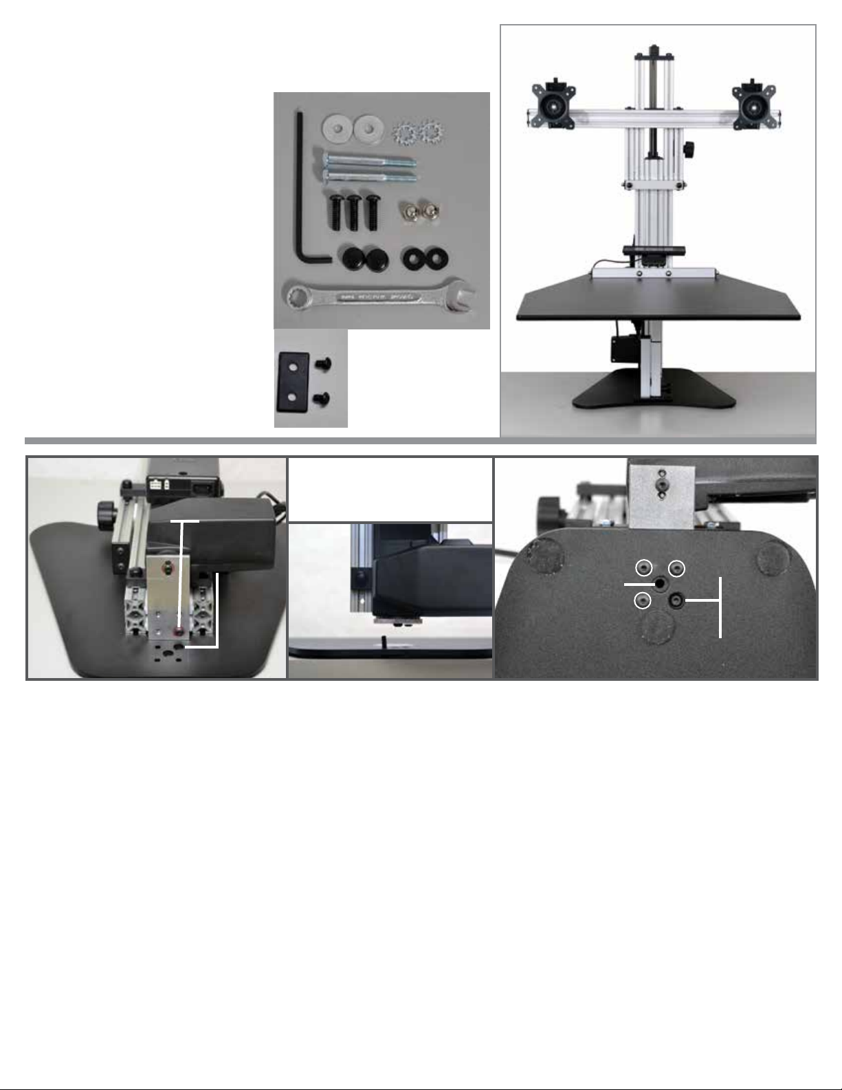
Assembly Parts list
A. (4) Black Screw Covers
B. (2) 1/4-20 x 3.50 Hex Head Bolts
C. (1) 5/32 Allen Wrench
D. (2) Fender Washers
E. (2) Acorn Nuts
F. (3) 1/4-20 x 7/8 BHCS (THESE 3
ARE ALREADY THREADED IN THE
LIFT ASSEMBLY)
G. (2) Thick Black Washers
H. (1) 7/16 Wrench
I. (2) Locking Star Washers
J. 1 x 2 plastic cap
K. (2) 1/4-20 x 3/8 BHCS
A
B
CD
E
F
G
H
I
J
K
(2) (2)
Steps 1-4 attaching the steel base plate to the lifting assembly
Step 1: Lay the lifting assembly on a solid surface with the back side up as shown. Notice the circled Button Head
Bolt in the assembly union plate. DO NOT LOOSEN THE SINGLE BUTTON HEAD BOLT THAT IS NOTATED.
LOOSEN AND REMOVE THE 3 OTHER BOLTS TO ADD THE LIFTING ASSEMBLY TO THE BASE PLATE.
Step 2: Notice the (2) oversized holes in the Base Plate. The Single Button Head Bolt will go into the oversized hole
on the top right, while the other 3 holes should line up with the base. The center oversized hole is not used with
this unit.
Step 3: With the Base Plate over hanging the table about 2 inches, hold the Lifting Assembly above the Base Plate
and align the Single Button Bolt into the oversized hole. Place (1) 1/4-20 x 7/8 BHCS{F} through the base plate to
screw in the lifting assembly. *DO NOT OVER TIGHTEN AT THIS POINT, WAIT UNTIL ALL BUTTON HEADS HAVE
BEEN ADDED.
Step 4: Insert and thread the other (2) 1/4-20 x 7/8 BHCS{F} through the Base Plate and into the Lifting Assembly.
Once all (3) bolts are threaded in, tighten securely with the 5/32 allen wrench{C}. Lifting Assembly should be at
against the Base and all three bolts should look like the picture above.
Step 1, 2 Step 3 Step 4
lifting
assembly
top of steel base plate
not used
image shows back side of
lifting assembly lining up the button
head bolts
single
button
head
oversized
hole to
match with
button
head
screw
bottom of lifting assembly
three button heads that need
screwed in and tightened
oversized hole
matched
up with already
installed
button head
bottom of base plate

The elecTric eliTe - Assembly Instructions Raise the lifting assembly to attach the
shelf button and work surface
Step 8: Put (1) Locking Star Washer{I} on each of the 1/4 –20 x 3.50
Hex Head Bolts{B}.
Step 9: Insert the (2) 1/4-20 x 3.50 Hex Head Bolts{B} through the
holes in the Vertical Rail.
Step 10: Put (1) Fender Washer{D} on each of the 1/4-20 x 3.50
Hex Head Bolts{B} on the other side of the Vertical Rail.
Step 11: Lift the Work Surface up and align the holes in the Hor-
izontal Rail with the (2) 1/4-20 x 3.50 Hex Head Bolts{B}. Push the
Work Surface onto the Hex Head Bolts until the threads of the
bolts come through the Horizontal Rail.
Step 12: Put (1) Black Washer{G} and (1) Acorn
Nut{E} on the end of each of the Hex Head
Bolts. Using the 7/16 wrench{H} tighten the
Acorn Nuts securely.
Acorn Nuts
Step 5: Connecting the
power for the lifting
assembly. Go to the back
side of the lifting assem-
bly and turn the power
box to the left. Push the
plug securely into the
power box. Tilt back to a
vertical position.
Step 6: Connecting the controller from the shelf and cable to
the actuator/motor. Connect the cable from the controler into
port “A1“ on the power box. Then connect the loose cable from
the motor to the provided extension cable. Plug the other end
into the control box on the back into port 1 on the far right.
Step 7: Installing the electric switch
(DPG1C) and phone tray. After the base has been
attched, prep the tray by unscrewing the e-nuts
until they are on the end of the bolt. Slide the tray
on using the vertical channels of the lifting assem-
bly as shown. Slide the tray up about 2 inches (this
can be changed at any time), and lightly tighten
the two bolts with the provided allen wrench.
Once you have con-
nected your cables,
plug the unit into an
outlet and press up
against the bottom
of the button, you
will feel a ‘click’.
Raise the unit 3/4 of
the way up like the
picture to the left.
STEP 11
Fender
Washers
horizontal
rail
Work
Surface
We suggest keeping
the lifting assembly
raised up, to step 12.
Once step 12 is
completed the unit
can be lowered to
the complete sitting
position.
Provided
Extension Cable
STEP 8,9,10
Fender
Washer
1/4-20 x 3.50
Hex Head Bolt
Locking Star
Washer
Locking Star
Washer
STEP 12
Black Washers
Acorn Nuts
Shelf and controller
button
STEP 5
STEP 6
STEP 7
STEP 5

STEP 13 Adding the Horizontal Monitor Arm
The elecTric eliTe - Assembly Instructions
Step 13: Identify the e-nuts(pictured above) that will hold the monitor bar. Loosen each
e-nut to about one thread to slide onto the rails.
Step 14: Slide on the monitor rail by using the bottom rail pictured above. Line up the
monitor rail to the desired location(usually centered).
Step 15: Identify the two hex head bolts holding the monitor rail pictured above
(located on the back of the unit). Once you have the monitor bar to your desired
location, tighten each bolt with the provided 7/16 wrench to a snug position.
Step 16: Adding the end-cap to your horizontal bar. On the exposed side of the rail
you will need to place the provided 1x2” rectangular black plastic cap{J}. Secure the
cap by adding (2) 3/8” button head bolts{K} with the provided allen wrench.
Step 17: Place black caps over any exposed hex head bolts. Follow the instructions
below to mount your monitor.
STEP 13 STEP 14 STEP 15 STEP 16
e-nuts to
loosen
hex head bolts
need tightened
J. 1x2”
end cap
K. button
head bolts
back side
Raise the lifting assembly to attach the
shelf button and work surface
Fender
Washer

The STabilizaTion leg
Your adjustable height desk top unit comes with an adjustable leg that can be used to give you maxi-
mum stability when you are using “The Kangaroo” in the standing position.
Raise the Kangaroo work surface to your desired standing height and tighten the work surface brake.
Place the adjustable leg under the work surface and loosen the adjustable leg brake. Only loosen the
brake by a turn or two, too much and the brake will disengage from the slot.
Extend the adjustable leg until it engages the bottom of the work surface and then tighten the adjust-
able leg brake.
The leg is shipped with the extension section installed to give you additional height adjustment. If this
is too tall for your application, simply unscrew the extension selection.
If you have the taller version of the leg there is no top extension selection.
A. Extension selection
B. Extension selection screws into this location
AlwAys remove the stAbilizAtion leg before
lowering the unit
The elecTric eliTe - IN USE INSTRUCTIONS The Electric Elite is designed to hold (2)
monitors on the VESA 75 x 75 or 100 x
100mm compatible brackets and your
keyboard and mouse on the main work
surface. The Electric Elite has a spring that
assists in raising/lowering your monitors and
works best when your monitors are in place.
This reduces the amount of pressure needed
to lower the monitors.
The main work surface is powered by an
electric motor and can lift up to 150lbs.
When raising and lowering the unit, please
be aware of your surroundings and cable
lengths. When lowering be sure to remove
the leg and make sure no objects are
obstructing the down travel.
To move the mount
horizontally closer
or farther apart, simply
loosen the bolt
attached to the hori-
zontal monitor rail (B)
by a single turn with
a 5/32 allen wrench.
Once you have
reached the desired
position re-tighten
the bolt.
Raise and lower the monitor rail by
loosening the monitor brake(A) and either
lift up or push down on the monitor rail(B).
Once the monitors reach your desired level,
tighten the monitor brake.
Raise and lower the main work surface by
pressing up and down respectably on the
button surface.
B. horizontal
monitor rail
A. monitor
brake
C. control
button
The conTrol buTTon
The controller button now has expanded features including bluetooth, memory settings, digital display, sit/stand
reminders, and auto-drive. To learn the programming functions, faqs, and troubleshooting of the control button
please visit the orange link below or scan the qr code to the right. For basic operation simply press down on the
controller to lower and lift the controller to raise. Your unit is pre-programmed
to only auto-drive when favorite heights are set. If there are no favorites the unit
will only move continuously while holding the button down. !!!!ALERT when using
autodrive you accept full responsibility when operating the desk and understand
the danger that can occur. Make sure no items are between the work surface and
base plate when lowering or above the unit when raising!!!
hTTpS://www.ergodeSkTop.com/SiTeS/defaulT/fileS/ergo-conTrol-manual.pdf
THE
KANGAROO ELITE
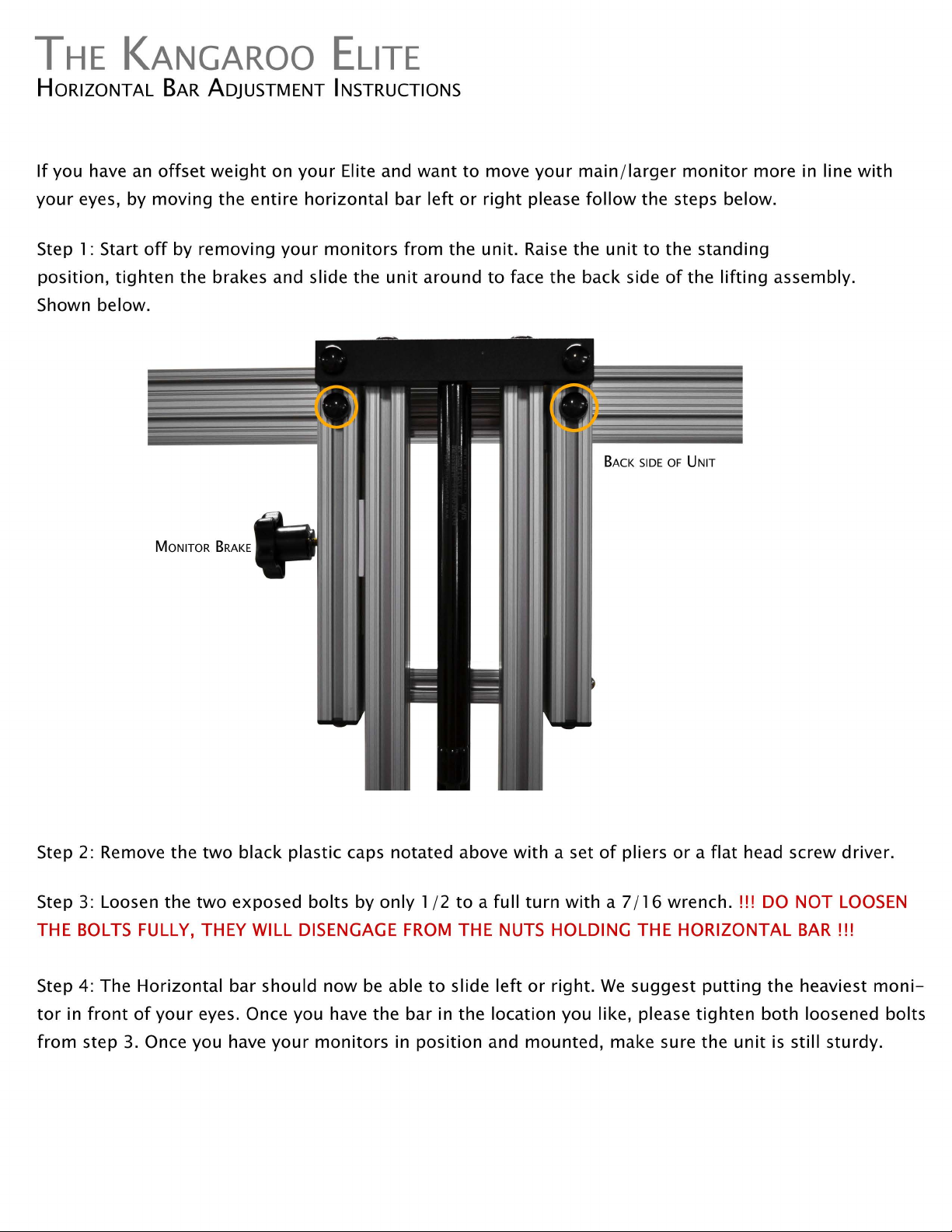
HORIZONTAL BAR ADJUSTMENT INSTRUCTIONS
If
you have
an
offset
weight
on
your
Elite and want
to
move
your
main/larger
monitor
more in line
with
your
eyes, by moving the entire
horizontal
bar
left
or
right
please
follow
the steps below.
Step 1: Start
off
by removing
your
monitors
from
the unit.
Raise
the
unit
to
the standing
position,
tighten
the brakes and slide the
unit
around
to
face the back side
of
the
lifting
assembly.
Shown below.
BACK
SIDE
OF
UNIT
MONITOR
BRAKE
Step 2: Remove the
two
black plastic caps notated above
with
a set
of
pliers
or
a
flat
head screw driver.
Step 3: Loosen the
two
exposed bolts by
only
1/2
to
a
full
turn
with
a 7/ 16 wrench. !!!
DO
NOT
LOOSEN
THE
BOLTS
FULLY, THEY WILL DISENGAGE
FROM
THE
NUTS
HOLDING THE HORIZONTAL
BAR!!!
Step 4: The Horizontal bar should
now
be
able
to
slide
left
or
right.
We
suggest
putting
the heaviest
moni-
tor
in
front
of
your
eyes. Once you have the bar in the location you like, please
tighten
both
loosened bolts
from
step
3.
Once you have
your
monitors
in position and
mounted,
make sure the
unit
is
still sturdy.
Other manuals for The Electric Elite
1
Table of contents
Other Ergo Desktop Indoor Furnishing manuals


Popular Indoor Furnishing manuals by other brands

Regency
Regency LWMS3015 Assembly instructions

Furniture of America
Furniture of America CM7751C Assembly instructions

Safavieh Furniture
Safavieh Furniture Estella CNS5731 manual

PLACES OF STYLE
PLACES OF STYLE Ovalfuss Assembly instruction

Trasman
Trasman 1138 Bo1 Assembly manual

Costway
Costway JV10856 manual


