Ericsson GE PCS 136-174 MHz User manual
Mobile Communications
PCS
136-174 MHz
Synthesized Portable Radio
LBI-38956
Maintenace Manual
Table of Contents
Front Assembly (Front Cap Assembly &
Audio Logic Board) . . . . . . . . . . . . . . . . . . . . . . . . LBI-38975
Rear Assembly (RF Board) . . . . . . . . . . . . . . . . . . . . LBI-38275
Service Section . . . . . . . . . . . . . . . . . . . . . . . . . . LBI-38623

Copyright © April 1994, Ericsson GE Mobile Communications Inc.
TABLE OF CONTENTS
Page
PACKAGE NOMENCLATURE . . . . . . . . . . . . . . . . . . . . . . . . . . . . . . . . . . . . . . . . . . . 3
SPECIFICATIONS . . . . . . . . . . . . . . . . . . . . . . . . . . . . . . . . . . . . . . . . . . . . . . . . . . 4
FCC Filing Data . . . . . . . . . . . . . . . . . . . . . . . . . . . . . . . . . . . . . . . . . . . . . . . . . 4
General . . . . . . . . . . . . . . . . . . . . . . . . . . . . . . . . . . . . . . . . . . . . . . . . . . . . . 4
Transmitter . . . . . . . . . . . . . . . . . . . . . . . . . . . . . . . . . . . . . . . . . . . . . . . . . . . . 5
Receiver . . . . . . . . . . . . . . . . . . . . . . . . . . . . . . . . . . . . . . . . . . . . . . . . . . . . . 5
OPTIONSANDACCESSORIES . . . . . . . . . . . . . . . . . . . . . . . . . . . . . . . . . . . . . . . . . . . 6
DESCRIPTION . . . . . . . . . . . . . . . . . . . . . . . . . . . . . . . . . . . . . . . . . . . . . . . . . . . . 9
Radio Programming . . . . . . . . . . . . . . . . . . . . . . . . . . . . . . . . . . . . . . . . . . . . . . . 9
Assembly . . . . . . . . . . . . . . . . . . . . . . . . . . . . . . . . . . . . . . . . . . . . . . . . . . . . 9
Standard Features . . . . . . . . . . . . . . . . . . . . . . . . . . . . . . . . . . . . . . . . . . . . . . . . 10
CONTROLS AND INDICATORS . . . . . . . . . . . . . . . . . . . . . . . . . . . . . . . . . . . . . . . . . . 12
Controls . . . . . . . . . . . . . . . . . . . . . . . . . . . . . . . . . . . . . . . . . . . . . . . . . . . . . 12
Indicators . . . . . . . . . . . . . . . . . . . . . . . . . . . . . . . . . . . . . . . . . . . . . . . . . . . . 13
Transmit Mode . . . . . . . . . . . . . . . . . . . . . . . . . . . . . . . . . . . . . . . . . . . . . 13
Receive Mode . . . . . . . . . . . . . . . . . . . . . . . . . . . . . . . . . . . . . . . . . . . . . 13
Alert Tones . . . . . . . . . . . . . . . . . . . . . . . . . . . . . . . . . . . . . . . . . . . . . . . 14
RADIO OPERATION . . . . . . . . . . . . . . . . . . . . . . . . . . . . . . . . . . . . . . . . . . . . . . . . . 14
To Receive AMessage . . . . . . . . . . . . . . . . . . . . . . . . . . . . . . . . . . . . . . . . . . . . . . 14
To Send AMessage . . . . . . . . . . . . . . . . . . . . . . . . . . . . . . . . . . . . . . . . . . . . . . . 14
To Place ADTMF Call . . . . . . . . . . . . . . . . . . . . . . . . . . . . . . . . . . . . . . . . . . . . . 15
OPERATIONAL FEATURES . . . . . . . . . . . . . . . . . . . . . . . . . . . . . . . . . . . . . . . . . . 15
Automatic Number Identification . . . . . . . . . . . . . . . . . . . . . . . . . . . . . . . . . . . 15
Type 99 Tone . . . . . . . . . . . . . . . . . . . . . . . . . . . . . . . . . . . . . . . . . . . . . . 17
Channel Busy Lock-Out . . . . . . . . . . . . . . . . . . . . . . . . . . . . . . . . . . . . . . . . 17
SCAN OPERATION . . . . . . . . . . . . . . . . . . . . . . . . . . . . . . . . . . . . . . . . . . . . . . . . . 17
Scan Vocabulary . . . . . . . . . . . . . . . . . . . . . . . . . . . . . . . . . . . . . . . . . . . . . . . . . 17
Pre-Scan Operation . . . . . . . . . . . . . . . . . . . . . . . . . . . . . . . . . . . . . . . . . . . . . . . 18
Scan Operating Modes . . . . . . . . . . . . . . . . . . . . . . . . . . . . . . . . . . . . . . . . . . . . . 19
Simple SCAN . . . . . . . . . . . . . . . . . . . . . . . . . . . . . . . . . . . . . . . . . . . . . 19
Priority SCAN . . . . . . . . . . . . . . . . . . . . . . . . . . . . . . . . . . . . . . . . . . . . . 19
Scanning for Channel Guard . . . . . . . . . . . . . . . . . . . . . . . . . . . . . . . . . . . . . 20
TONE PROGRAMMING . . . . . . . . . . . . . . . . . . . . . . . . . . . . . . . . . . . . . . . . . . . . . . 20
GE Type 99 Format . . . . . . . . . . . . . . . . . . . . . . . . . . . . . . . . . . . . . . . . . . . . . . . 21
Motorola Format . . . . . . . . . . . . . . . . . . . . . . . . . . . . . . . . . . . . . . . . . . . . . . . . . 21
Individual Call . . . . . . . . . . . . . . . . . . . . . . . . . . . . . . . . . . . . . . . . . . . . . 22
Group Call (Quick Call Format) . . . . . . . . . . . . . . . . . . . . . . . . . . . . . . . . . . . . 22
Channel Guard . . . . . . . . . . . . . . . . . . . . . . . . . . . . . . . . . . . . . . . . . . . . . . . . . . 23
Replacement Of Battery Pack . . . . . . . . . . . . . . . . . . . . . . . . . . . . . . . . . . . . . . . . . . 24
To Remove the Battery Pack from the Radio . . . . . . . . . . . . . . . . . . . . . . . . . . . . . 25
To Re-Connect the Battery Pack to the Radio . . . . . . . . . . . . . . . . . . . . . . . . . . . . 25
RECHARGING THE BATTERY PACKS . . . . . . . . . . . . . . . . . . . . . . . . . . . . . . . . . . . 25
INTRINSICALLY SAFE USAGE . . . . . . . . . . . . . . . . . . . . . . . . . . . . . . . . . . . . . . . 25
Reduced Capacity in Nickel/Cadmium Batteries . . . . . . . . . . . . . . . . . . . . . . . . . . . 25
Disposal . . . . . . . . . . . . . . . . . . . . . . . . . . . . . . . . . . . . . . . . . . . . . . . . 26
MECHANICALPARTS BREAKDOWN . . . . . . . . . . . . . . . . . . . . . . . . . . . . . . . . . . . . . . 27
MECHANICALPARTS LIST . . . . . . . . . . . . . . . . . . . . . . . . . . . . . . . . . . . . . . . . . . . . 28
LBI-38956
2

PACKAGE NOMENCLATURE
Digits 1 & 2 Digit 3 Digits 4 & 5
Digit 6
Product
Code Frequency
Range Number of
Channels
Package
S
SCAN
1
136-153
MHz
02
2 Channels
PC
2
150-174
MHz
08
8 Channels
D
DTMF
16
16 Channels
LBI-38956
3

SPECIFICATIONS*
FCC FILING DATA
FCC Identifier
136-153 MHz AXA9Z-PCSH1
150-174 MHz AXA9Z-PCSH2
FCC Part Numbers
136-153 MHz Parts 20 & 90
150-174 MHz Parts 22, 74, 80, & 90
GENERAL
Frequency Range 136-174 MHz
RF Power Range 1-5 Watts
Input Voltage 6.0 to 9.0 Volts
Channel Capacity 2, 8, or 16 Channels
Frequency Spread (Full Performance)
136-153 MHz 17 MHz
150-174 MHz 24 MHz
Frequency Stability ±5 PPM
Channel Spacing 30/25 kHz
Dimensions (less antenna) H x W x D
with 1200 mAh Battery 7.4 x 2.8 x 1.57 inches (18.8 x 7.11 x 4.0 cm)
with 1700 mAh Battery 8.8 x 2.8 x 1.57 inches (22.35 x 7.11 x 4.0 cm)
Weight
Radio (less battery) 11 ounces
1200 mAh Battery 9 ounces
1700 mAh Battery 13.5 ounces
Ambient Temperature Range -30° to +60°C (-22° to +140°F)
Vibration Meets EIA, U.S. Forest Service, and MIL 810 specifications
Battery Drain (7.5 VDC)
Receiver Standby 60 milliamperes
Receiver Full Audio 250 milliamperes
Transmit (@5 watts) 1.8 amperes
Transmit (@2 watts) 1.3 amperes
Battery Life (between charges) 1200 mAh 1700 mAh
Hi Power (5-5-90% duty cycle) 8.0 hours 11.3 hours
Lo Power (5-5-90% duty cycle) 9.5 hours 13.4 hours
LBI-38956
4

TRANSMITTER
Power Output
Hi Power 5 watts
Lo Power 2 watts (adjustable to 1 watt)
Conducted Spurious -65 dB
Modulation Deviation ±5.0 kHz (maximum)
Audio Response Within 1 dB and -3 dB of a standard 6 dB/octave pre-emphasis
from 300 to 3000 Hz per EIA.
FM Noise (companion receiver method) -45 dB
Power Adjust Range 1 to 5 Watts
Distortion 5% (maximum)
Deviation Symmetry 0.1 kHz
RF Output Impedance 50 Ohms
Carrier Attack Time 35 milliseconds
Audio Attack Time 35 milliseconds
RECEIVER
Audio Output (EIA) 0.5 Watts (<5% distortion)
Sensitivity
12 dB SINAD (EIA) -119 dBm (0.25 µV)
Selectivity
(EIA 2-signal method) -70 dBm @ ±30 kHz
Spurious Response -70 dB (Half IF spurious -60 dB from 150 MHz to 160 MHz)
Intermodulation -70 dB
Hum and Noise
Squelched -80 dB
Unsquelched -48 dB
Modulation Acceptance ±7 kHz
Frequency Response Within +2 dB and -8 dB of a standard 6 dB/octave
de-emphasis curve from 300 to 3000 Hz (EIA).
RF Input Impedance 50 Ohms
* These specifications are intended primarily for use by service personnel. Refer to the appropriate Specification Sheet for
complete specifications.
The software contained in this device is copyrighted by the Ericsson GE Mobile Communications Inc. Unpub-
lished rights are reserved under the copyright laws of the United States.
NOTICE
LBI-38956
5

OPTIONSAND ACCESSORIES
BATTERYPACKS
DESK CHARGERS
PCPA1J
1200 mAh
(19A705293P1)
PCPA1K
1700 mAh PCPA1L
1700 mAh
(19A705293P3)
Factory Mutual
Standard
CHISS1 (120 VAC)
CHISS2 (230 VAC)
ANTENNA
PCNC1P
(19B801620P10)
136-174 MHz
Rapid
CHIRS1 (120 VAC)
CHIRS2 (230 VAC)
LBI-38956
6

OPTIONSAND ACCESSORIES
(continued)
CARRYINGACCESSORIES
Belt Clip
PCHC1C
(Option Package 19B233241G1)
(Modification Kit 19A144704G1)
Swivel Plate
PCHC1D
(Belt Loop 19B226627G2)
(Swivel Option 19B233243G1)
Earpiece Kit
PCZM1A
Incudes PCPA1C
Accessories Connector
PCAC1C (19C851752P7)
Speaker/Microphone
PCAE1X
LBI-38956
7

OPTIONSAND ACCESSORIES
(continued)
CARRYING CASES
PCHC5S
1200 mAh Battery Pack
Full Cover 19D902456P15
PCHC5T
1200 mAh Battery Pack
Retaining Strap 19D902456P7
PCHC5U
1700 mAh Battery Pack
Full Cover 19D902456P18
PCHC5V
1700 mAh Battery Pack
Retaining Strap 19D902456P7
LBI-38956
8

DESCRIPTION
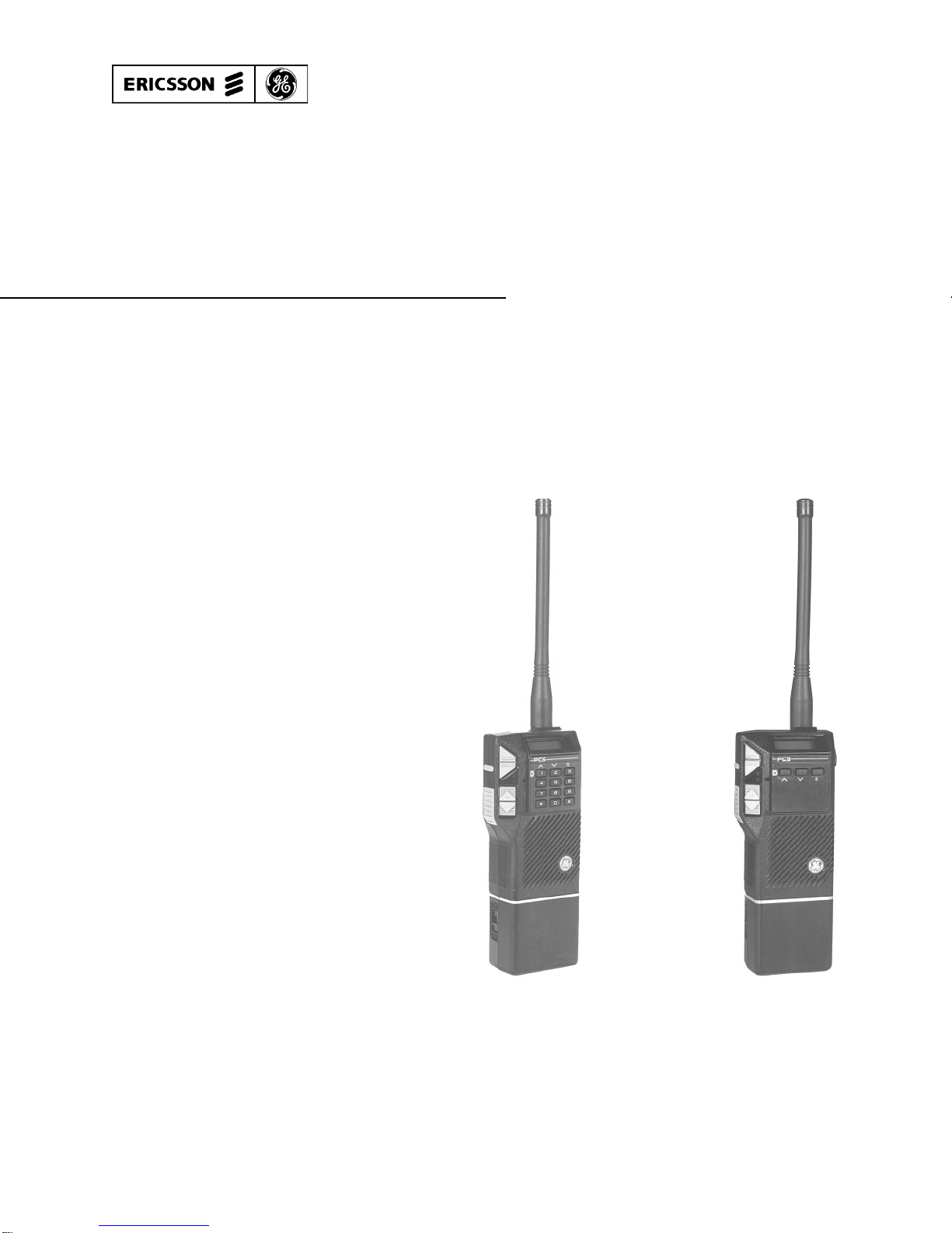
The PCS Standard and DTMF Portable radios are small,
ruggedly constructed, two-way FM radios, housed in an alu-
minum and LEXAN case. The VHF synthesized radios op-
erate in the 136-174 MHz range and they can be purchased
with 2, 8, or 16 channel operation.
Operating controls for the radio are provided through a
rubber keypad on the side and front of the radio (a three-
button keypad on the Standard version and a twelve-button
keypad on the DTMF). All keypad switches have a good
tactile feel and are sealed to provide weather protection.
When turned "ON," the radio powers-up on the last channel
used and at the last volume setting. The operating controls,
UDC, and battery pack are shown in Figure 1.
All the PCS radios are equipped with a Universal De-
vice Connector (UDC) for connecting external options and
for programming the radios. The radios are programmed
using a personal computer and programming interface box
that connects to the UDC. The UDC is covered with a rub-
ber cover for improved weather protection.
The PCS uses a BNC antenna connector. The antenna
base is overmolded to fit flush against the housing for added
weather protection.
The radio battery pack securely latches in place at the
bottom of the radio. The radio ON/OFF switch is located
on the battery pack.
A Liquid Crystal Display (LCD) on the front of the ra-
dio shows the selected channel, volume level, SCAN mode
(SCN)*, and priority level (P1, P2, or S). The 2-channel ra-
dio uses the P1 and P2 pixels for high and low transmit
power indicators, respectively. In addition, the "S" pixel is
used to indicate "Talkaround" mode. The LCD also has a
transmit (TX) indicator, a low battery voltage indicator
(BAT), and a Type 99 paging (PG) indicator. There are
eight (8) levels of volume represented by the four (4) bars in
the LCD. Each bar represents two (2) volume levels. The
LCD module is backlit for night viewing and is mounted in
a rubber seal for weather protection.
The radio is shipped from the factory with the high
power level set to 5 watts and the low power level set to 2
watts.
*SCAN applies to the 8 and 16 channel PCS radios.
RADIO PROGRAMMING
Each of the 8 or 16 channel radios can be programmed
for SCAN operation, and Home Channel or Emergency
Channel, in addition to the Tone or Digital Channel Guard,
Squelch Tail Elimination (STE), Type 99 Tone Decoding,
Automatic Number Identification (ANI), channel busy lock-
out, and HI/LO transmit power level available on the con-
ventional 2-channel radio. These options can be
programmed on a channel-to-channel basis. Two different
T99 Tone tables can be programmed into the PCS. Each
channel is capable of Individual Group or Super Group De-
code.
Other programmable features include Carrier Control
Timer (CCT), display backlighting, and alert beep options.
These features can be programmed, as desired, to meet sys-
tem requirements.
Refer to the programming manual (TQ3366) for com-
plete programming instructions.
ASSEMBLY
The PCS personal radio consists of an RF board
mounted in the rear assembly, an audio/logic board mounted
in the front assembly, and a control frame assembly.
The RF board contains all transmit, receive, and synthe-
sizer circuits. The audio/logic board contains all transmit
audio and receive audio circuits along with all logic and
control circuits. A microprocessor on the audio/logic board
generates and decodes all tones used in Channel Guard or
Type 99 tone signalling.
The control frame assembly mounts in the radio front
cover and provides the following functions:
•Audio/Logic board interface.
•Microphone and speaker connections.
•Houses the channel up/down, volume up/down,
monitor, and PTT switches.
When the battery is low, the low battery indicator
(BAT) is displayed on the LCD and an audio alert is
sounded every 7.5 minutes. When the battery is suf-
ficiently low to cause improper operation, the radio
microprocessor terminates all operation.
NOTE
LBI-38956
9

•UDC interface to the outside of the radio for external
options and customer programming.
•Houses the LCD module for status display.
Refer to the Interconnection diagram (listed in theTable
of Contents of the Service Section of this manual) for all
circuit board and control frame connections.
STANDARD FEATURES
In addition to dual-priority SCAN (in 8 and 16 channel
operation), DTMF dialing, Channel Guard, Digital channel
Guard, STE, ANI, Type 99 Decode, and transmitter power
level settings, the PCS radio includes the following standard
features:
1. Monitor Allows the operator to monitor channel
activity before transmitting by disabling
either Channel Guard or the squelch cir-
cuit.
2. Carrier
Control
Timer
The carrier Control Timer is program-
mable from 15 to 225 seconds in 15 sec-
ond increments or it can be disabled.
3. Channel
Busy
Lock-out
This feature prevents the transmitting of
a message on a busy channel.
4. Radio
Memory The radio memory remembers the radio
status such as the last volume level,
channel selected, and SCAN status.
These settings are stored in memory
while the radio is turned off.
5. Surveillance
Feature The earphone, external microphone in-
put, and PTT options are available for
surveillance purposes.
6. TalkAround Each channel in the 2-channel radio can
be put into Talk Around mode. The 8
and 16 channel radios can be pro-
grammed for a Talk Around channel.
7. Power Set The TX power set on the 2-channel ra-
dio can be toggled between 1 and 5
watts. Power can be set by the PC pro-
grammer for all radios.
8. Audio Alert
Beep Usual alert beeps will not be sounded
when this feature is disabled. However,
the T-99, P1 priority, and ANI end beeps
will be sounded.
9. LCD
Backlight On the 2-channel radio, the backlight
can be turned on by pressing the ∧but-
ton. The backlight will remain illumi-
nated as long as the button is pressed
and will remain illuminated for 5 sec-
onds after the button has been released
(provided the button was pressed for at
least 1 second). Backlight will not be
turned on when this feature is disabled.
In the 8 and 16 channel radios, LCD
backlighting is turned on every time a
control button is pressed (channel se-
lect, volume up/down, and monitor) and
remains on for another 5 seconds after
the control button is released (provided
the control button was pressed for at
least one second). Backlighting is
turned off while transmitting and will il-
luminate again for 5 seconds after the
PTT is released.
10. Self-Test The PCS radio is equipped with a self-
test feature that is performed during
power-up of the unit. A good self-test is
indicated by a series of three (3) beeps,
if enabled, followed by the last radio
status on the LCD. All of the display
segments are turned on during the three
beeps. A bad self-test will cause all dis-
play segments to remain on and no
beeps will be sounded.
11. Battery
Voltage Level The BAT display is illuminated any
time the battery voltage level drops be-
low the low level (6.3 volts). BAT is
displayed and continues to be displayed
on the LCD until the battery is charged
or a fresh battery pack is connected. An
audio alert is also sounded every 7.5
minutes while the BAT display is illu-
minated.
When the battery voltage goes low while transmitting,
BAT will be displayed and will continue to be displayed af-
ter returning to the receive mode. BAT will be turned off af-
ter 5 seconds unless the battery voltage level is also low in
the receive mode.
Below 6.3 volts, BAT will continue to be displayed.
End of battery is considered to be 5.8 volts. This level will
allow at least one hour of EIA operation. The radio will
continue to operate at reduced power levels below 5.8 volts.
Below 5 volts, radio operation is completely disabled to pre-
vent corruption of the radio personality.
LBI-38956
10

Figure 1 - PCS Operating Controls
LBI-38956
11

The simultaneous flashing of the BAT indicator and the
sounding of alert beeps, if programmed, indicates the radio
has failed to lock on frequency. Transmission will be termi-
nated any time the radio is in the transmit mode and the syn-
thesizer fails to lock on frequency.
CONTROLS AND INDICATORS
CONTROLS
The radio controls consist of an ON/OFF switch, a
MONitor and PTT switch, volume and channel select but-
tons, SCAN/Talk Around buttons (∧), DELete/Power Set
buttons (∨), and ADD/HOME/BACKLIGHT controls (S).
ON/OFF The ON/OFF slide switch on the battery pack,
controls power from the battery pack to the radio.
When turned "ON," an audible click is heard and
a yellow square is visible beneath the switch.
The radio assumes the last operating state (i.e.,
channel volume, etc.). This status will be dis-
played in the LCD window, indicating power is
applied. BE SURE the power switch is fully ON
(or fully OFF).
MON The MONitor switch can be programmed for 2
different modes of operation: Channel Guard or
Squelch.
Mode 1 (Channel Guard) - Receive Channel
Guard can be disabled at any time by briefly
pressing (for less than 1 second) and releasing
the MONitor/Channel Guard button. The Chan-
nel Guard disabled condition is indicated by the
flashing volume level bars on the display. After
holding the button for more than 1 second, the
button becomes a true monitor switch and opens
the receiver.
Mode 2 (Squelch) - All channel activity can be
monitored by pressing and holding the MONitor
button for up to three seconds. After three sec-
onds, Channel Guard is disabled as indicated by
the flashing volume bars on the display.
Channel Guard Disable Reset
Common to both CG and Squelch modes, Chan-
nel Guard disable reset can also be programmed
for either manual or auto operation.
Manual: Once the Receive Channel Guard is dis-
abled, it remains disabled in receive mode
regardless of the channel change or PTT.
Auto: Receive Channel Guard will automat-
ically be re-enabled after the PTT is acti-
vated.
Channel Guard is always enabled when transmit-
ting, regardless of the Channel Guard switch set-
ting in receive mode.
Type 99 Reset
When the radio is inType 99 Monitor mode, press-
ing and holding the MONitor button for any length
of time reverts the radio to Selective mode. See
Type 99 section for details.
PTT The radio is keyed by pressing and holding the
PTT (Push-to-Talk) button. Regardless of the
Channel Guard switch setting (disabled or en-
abled), Channel Guard is always enabled during
transmission (see Channel Guard switch section).
This button is also used for selecting the monitor
mode on T99 channel (see Type 99 section).
"S" This button turns the SCAN mode on and off in the
8 and 16 channel radios. It must also be pressed
while adding or deleting channels from the Scan
list (see ∧ and ∨ sections). On the 2-channel radio,
this button puts the radio in Talk Around mode.
∧This control button is used for three different func-
tions in the 8 and 16 channel radios.
ADD - While the "S" button is pressed, pressing
the ∧button will "add" the selected channel to the
Scan list or increase the channel’s priority status in
the Scan list (e.g., Non-SCAN to Non-Priority,
Non-Priority to Priority 2, and Priority 2 to Priority
1). This procedure can only be accomplished
when the SCAN mode is off.
HOME - When activated alone (without the
SCAN button), this button is used to revert the se-
lected channel to a pre-programmed HOME chan-
nel. If SCAN mode is "ON" prior to pressing this
key, scanning will stop. However, the radio will
resume scanning if the channel, volume, or PTT
button is not pressed within 5 seconds.
EMERGENCY - If programmed as an EMER-
GENCY button and no HOME channel is pro-
grammed, press and hold the button for at least
one second to transmit the emergency ANI code on
the selected channel. If the radio is programmed
with a HOME channel, the emergency ANI code
LBI-38956
12

will be transmitted on the HOME channel instead
of the elected channel.
If the radio is scanning when the ∧ button is
pressed and no HOME channel is programmed, the
radio will stop scanning, transmit the emergency
ANI code on the selected channel, and resume
scanning. If the radio is scanning when the button
is pressed and a HOME channel is programmed,
the radio will stop scanning, transmit the emer-
gency ANI code on the HOME channel, switch the
receive operation to the HOME channel, and re-
sume scanning.
Emergency transmissions can only be disabled by
turning the radio off and then back on.
BACKLIGHT - In 2-channel radio operation, this
button illuminates the backlight. BACKLIGHT
will be illuminated when the button is pressed and
will remain on for 5 seconds after the button is re-
leased (provided the button was pressed for at least
one second).
∨In 8 and 16 channel radios, while the "S" button is
being pressed, activating the ∨ button will remove
(delete) the selected channel from the Scan list.
Radio operating status is not altered when this but-
ton is activated alone.
In the 2-channel radio, this button toggles the TX
power between 2 and 5 watts.
CHAN
UP/
DOWN
The CHAN UP/DOWN button selects the trans-
mit/receive channel. Communications channels
are selected one at a time or progressively by
pressing and holding the CHAN UP/DOWN but-
tons. The next higher channel is always selected
(channel 1 follows channel 2, 8, or 16 for 2-, 8-, or
16-channel radios respectively).
VOL
ume The VOLume buttons set the receive audio to the
desired level while pressing the UP or DOWN but-
ton. Changing the volume level while the radio is
squelched causes the radio to beep, if programmed,
at the new selected level. No beep will sound
when the radio is already unsquelched. The rela-
tive volume level is indicated by the number of
bars illuminated in the LCD. There are eight (8)
levels of volume indicated by the four (4) bars on
the LCD; each bar represents two levels of volume.
Pressing and holding the volume buttons continues
to increment the volume in the direction indicated
on the button.
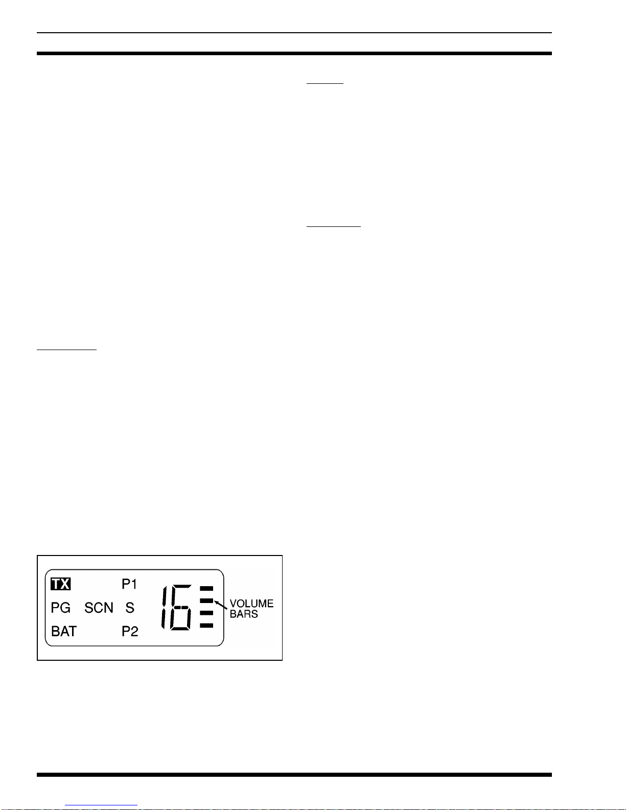
INDICATORS
The LCD shows the SCAN mode (for 8 and 16 channel
radios only); P1, P2, and S (Scan list) indicators; channel
number; volume level; battery condition; Type 99 Tone de-
code status; and transmit indicator (see Figure 2). With re-
gards to 8 and 16 channel operation, the LCD is backlit
anytime a control button is pressed. Backlighting is always
turned ON during transmit and remains on for 5 seconds af-
ter the PTT or control button is released, if programmed.
In the 2-channel radio, the high and low power are indi-
cated by the "P1" and "P2" pixels, respectively, and the "S"
pixel indicates the radio is in "Talkaround" mode.
The LCD indicators are shown below in the transmit and
receive mode.
Transmit Mode
TX TX indicates transmit mode when the PTT button
is pressed.
BAT BAT indicates battery voltage is low and the bat-
tery pack requires charging. when the battery pack
voltage reaches the low level while in the transmit
mode, BAT is illuminated and stays illuminated for
another 5 seconds after the radio is returned to the
receive mode. BA is turned off after five seconds
unless the battery pack voltage level is also low in
the receive mode.
Receive Mode
VOL The volume level (eight different levels) is indi-
cated by 4 bars on the LCD; each bar represents 2
volume levels.
PG This display indicates the selected channel pro-
grammed to receive Type 99 calls. Upon receipt of
a Type 99 call, the PG flag flashes until the Type
99 call decoder is reset.
The short beep indicator on volume change will
not be sounded when the speaker is already on.
NOTE
These options must be enabled by the PC Program-
mer before indicating status for the 2-channel radio.
NOTE
LBI-38956
13
SCN Indicates the SCAN mode is active in the 8- and
16-channel radios. This is not used in the 2-chan-
nel radios.
P1 Priority 1 enabled is represented by this display (in
8 and 16 channel radios). Represents high transmit
power on 2-channel radios.
P2 Priority 2 enabled is represented by this display (in
8 and 16 channel radios). Represents low transmit
power on 2-channel radios.
S This display indicates that non-priority is enabled
in 8 and 16 channel radios. Indicates "Talkaround"
mode is active on the 2-channel radios.
CHAN The transmit/receive channel is indicated by a
number in the LCD window.
BAT This is displayed in the LCD when the battery volt-
age is low.
Alert Tones
1. Series of 3 beeps: Self-test OK on Power-up.
2. Single beep: Channel or Volume change.
3. Series of beeps:
•Synthesizer out of lock.
•No transmit frequency when trying to transmit.
•Expired CCT.
•Channel busy indicator when the option is
enabled.
•T99 decode alert. (Service note: This is a
change from standard radios.)
Self-Test The radio performs a self-test at power-
up each time the radio is turned on. A
good (passed) self-test will be indicated
by three beeps, if programmed, fol-
lowed by the last radio status (channel
number, volume level, SCAN status,
etc.) being displayed in the LCD win-
dow. All segments of the display are
shown during the three beeps. If the
self-test fails, all segments will be illu-
minated but no beeps will be sounded.
BAT/ALERT Simultaneous flashing of BAT in the
LCD and the sounding of alert beeps, if
programmed, indicates failure of the
synthesizer to lock on frequency. If this
happens during transmission, the trans-
mitter will become inhibited and no
transmission will be made. The opera-
tor should select another channel, re-
charge the battery pack, or have the unit
checked.
RADIO OPERATION
This manual provides only elementary information re-
garding operation of the PCS personal radio. Refer to Op-
erator’s Manual (LBI-38955) for complete operating
instructions.
TO RECEIVE AMESSAGE
1. To turn the radio ON, slide the ON/OFF switch on
the battery pack to the ON position. A yellow-col-
ored area will be visible beneath the switch.
2. After the radio has passed the self-test, press and
hold the VOL UP or VOL DOWN button while lis-
tening to the beeps (if this feature is programmed).
Watch the LCD for the volume level indicators
(four bar lines) to select the desired listening level.
3. Press the CHAN UP or CHAN DOWN button to
select the operating channel.
4. The radio is now ready to receive messages.
TO SEND AMESSAGE
1. Turn the radio ON and select an operating channel
as instructed above in To Receive a Message. The
current status of the radio is displayed in the LCD
window.
Figure 2 - Liquid Crystal Display (LCD)
LBI-38956
14

2. Press the MONitor button to determine if the chan-
nel is in use. Never interrupt another conversation.
3. While holding the radio so that the antenna is verti-
cal, press the PTT switch and speak directly into
the grill or across the face of the radio or external
microphone. Speak in a normal voice. Release the
PTT switch as soon as the message is finished.
Messages (responses) cannot be received when the
PTT is being pressed.
4. When transmission is desired on a paging channel,
the PTT switch must be pressed twice. Press the
PTT switch the first time to take the radio out of
the paging mode. Press the PTT switch a second
time for normal PTT operation. Remember that a
PG flag flashes in the LCD window and the radio
beeps on the first press of the PTT switch.
The radio can be returned to the Type 99 paging
mode by pressing the MONitor button.
TO PLACE ADTMF CALL
Specific procedures for placing a telephone call from a
PCS DTMF radio are determined by the operating system
where the radio is used. Consult a system representative for
the exact operating procedures for the system.
The keypad on the PCS DTMF radio is not active until
the PTT switch is operated. Therefore, the PTT switch must
be pressed at all times when operating any button on the
DTMF keypad.
OPERATIONAL FEATURES
The radio is PC programmable to power-up in either Se-
lective (paging) or Monitor mode for channels programmed
for paging.
When Selective mode is chosen, the radio operates as a
tone and voice receiver, and allows only those calls that are
tone coded for the radio to be heard. Selecting Monitor
mode allows all calls with the correct Channel Guard (if
programmed) on the channel to be heard.
In either mode, when a correct T99 and Channel Guard
(if programmed and enabled) have been decoded, a series of
intermittent beeps will be heard to alert the operator of an
incoming call. A slow flashing PG flag will be illuminated
on the display to indicate that a call has been received.
When Selective mode is chosen, the radio switches auto-
matically to Monitor mode.
At the end of the message, if Selective mode is desired,
press and release the MONitor button to reset the Type 99
tone signalling function. The PG pixel on the display will
stop flashing at this time.
While in Selective mode, the radio can be put in Moni-
tor mode by pressing and releasing the PTT switch. Aseries
of beeps is sounded while the PTT is pressed, to indicate
that no transmission has occurred and the Monitor mode has
been selected as indicated by the flashing PG indicator.
However, any additional PTT activation will key the trans-
mitter.
The radio is programmable to decode any GE or Mo-
torola decode combinations from any one of two T99 tone
tables on a per-channel basis. TX and/or RX Channel
Guard can be programmed to any channel with T99.
Type 99 Receive Channel Guard (if programmed) can be
disabled, any time, by the procedure explained in the Moni-
tor/Channel Guard section. The volume level bars will
flash, indicating that Channel Guard has been disabled.
Automatic Number Identification
Automatic Number Identification (GESTAR) is a 320-
millisecond burst of code that is generated at the beginning
of each transmission to identify the PCS radio to the base.
If programmed, a beep is sounded at the end of ANI trans-
mission to indicate when conversation can begin as the mi-
crophone is disabled until the ANI transmission is
completed.
Systems with Channel Guard require the ANI be delayed
long enough for the system to respond before ANI can be
decoded. A programmable delay (0 to 2 seconds) is pro-
vided to meet this requirement. A delay of 350 millisec-
onds, for example, requires the operator to wait for 670
milliseconds after pressing the PTT switch before conversa-
tion can be started. The ID message can be programmed to
be sent at the end of a transmission, if desired.
Re-setting Type 99 from Monitor mode to Selective
mode does not affect the Channel Guard switch set-
ting.
NOTE
LBI-38956
15

FUNCTION PROGRAMMING DESCRIPTION
MONITOR Button Programmed for Channel Guard
Programmed for Squelch
Momentary Hold Down
DIS/ENABLE CG MONITOR
MONITOR DIS/ENABLE CG
Channel Guard Enable Manual
Auto
Must re-enable CG with MON button after transmitting
PTT will re-enable CG
ANI Front
End
ANI side tone
Delay
Sent at front of message
Sent at end of message
YES/NO: Tells operator when it is OK to talk. (Only
happens when front of message programmed.)
Independent of alert beep.
Delay for repeater to decode Channel Guard.
SCAN SCAN for CG
SCAN for TX channel
YES/NO:
Sel Ch (TX on select channel)
RX Ch (TX on received channel)
SCAN Hang time Time receiver remains locked on channel after carrier
drops (programmable).
Hang after PTT release YES/NO: If Yes, receiver stays on channel for
programmed hang time before SCAN resumes.
Beep on P1 YES/NO: Short beep after receiving P1 call.
(Independent of audio alert beep.)
SCAN Prog Mode Front- all channels programmed from keypad.
Fixed - P1 fixed by PC. Other channels keypad
programmed.
Selected - P1 follows selected channel. Other channels
keypad programmed.
T-99 Alert Beep
Alert Beep VOL
YES/NO: Alert beep rec PG
VOL MAX
DTMF Auto Dial Talk Number
Start Gap
Digit Length
Gap Length
Number to be dialed with or without *.
Delay between * and number.
Length of digits.
Gap between length.
Table 1 - PCS Function Guide
LBI-38956
16

ANI is enabled on a per-channel basis.
In summary, ANI variables are:
ID Number (0 to 8192)
Start Delay (0 to 2 seconds in 100 msec incre-
ments)
Beginning or End of transmission
Alert Beep ON/OFF
Per-channel basis selection (Channel 1 to 16)
Emergency ID
Type 99 Tone
1. Select the appropriate channel to receive Type 99
tone signalling. The PG flag will be displayed on
this channel.
2. When receiving a Type 99 call, answer in one of
the following two ways:
a. To reply to a message - After hearing theType
99 paging tone, press the PTT switch and an-
swer the call. After completing the communi-
cation, press the MONitor button to reset the
radio for the next call.
b. To avoid listening to a call - After hearing the
Type 99 paging tone, press the MONitor but-
ton to reset the radio for the next call.
3. Type 99 operation can be disabled by pressing the
PTT switch when the radio is in Selective mode.
While the switch is pressed, the radio beeps to in-
dicate that no transmission is occurring.
After releasing the PTT switch, the PG flag flashes
in the LCD window to indicate the radio is now in
the Monitor mode (CG or Squelch operation only).
Pressing the PTT switch results in a normal trans-
mission.
If the Scan list includes a Type 99 channel and is SCAN
enabled, the Type 99 tones will be ignored. SCAN operates
on a carrier and Channel Guard basis only.
Channel Busy Lock-Out
This feature is programmable on a per-channel basis. If
programmed, the transmit function is inhibited if the carrier
is being received with the incorrect Channel Guard. If the
correct Channel Guard is being received, transmission will
be allowed. If Channel Guard is disabled and a carrier with
the incorrect Channel Guard is received, the message will
be heard but transmission will still be inhibited. If no Chan-
nel Guard is programmed, Channel Busy Lock-Out is made
on carrier presence only. Type 99 cannot be programmed on
a channel with Channel Busy Lock-Out.
SCAN OPERATION
The SCAN function allows monitoring of up to 8 or 16
receive channels. The scanned channels can be any fre-
quency within the frequency band limits of the radio and
can be Channel Guard-protected (tone or digital).
Any channel can be scanned with or without a priority
level. One channel can be programmed for Priority 1 (P1)
and another for Priority 2 (P2) with any or all remaining
channels programmed as Non-Priority channels.
SCAN VOCABULARY
The following are terms frequently used when SCAN is
used:
Simple SCAN - Simple SCAN describes the condi-
tion that exists when there is no activity on any
channel in the Scan list.
Priority SCAN - Priority SCAN describes the con-
dition that exists when SCAN locks on a non-pri-
ority channel while sampling the Priority channels.
If a Type 99 channel is in the Scan list and
SCAN is enabled, the Type 99 tones are ig-
nored.
Scanning is provided on a carrier and Chan-
nel Guard basis only!
NOTE
Please note that all reference to SCAN, Scan
list, etc. applies only to the 8- and 16-channel
radios.
The 2-channel radios are not equipped with the
SCAN function.
NOTE
LBI-38956
17

Channel Guard SCAN - This is the scanning con-
dition where tone or digital Channel Guard must
also be detected before locking on any channel.
Selected Channel - This is the last channel that the
operator selected with the Channel Select buttons.
The channel selection can be done either with
SCAN active or inactive. This channel is also
shown in the display window in SCAN mode un-
less activity is detected on another channel being
scanned.
Received Channel - The received channel is a
channel that has been identified to have the correct
carrier and correct Channel Guard (if enabled).
The received channel number is shown in the dis-
play window.
HOME Channel - This channel is a high priority
channel that can be programmed for easy access.
This HOME channel is selected by pressing the ∧
button. Pressing this button changes the selected
channel to the HOME channel regardless of the
current selected channel. If SCAN mode is "on"
prior to pressing this key, scanning will stop.
However, if no control button is pressed (channel,
volume, or PTT) within 5 seconds, scanning will
resume.
Scan List - This is an internal list that is made of
channel numbers including their status, that will be
scanned when the SCAN mode is turned on. This
list is selected by the process explained in the
PRE-SCAN OPERATION section of this manual.
Non-SCAN Channel - A non-SCAN channel is a
channel that is not in the Scan list determined by
the operator. This channel is not normally
scanned.
Non-Priority Channel - This channel is on the Scan
list as established by the operator. Activity on this
channel will be interrupted by activity on either the
Priority 1 (P1) or Priority 2 (P2) channel.
Priority 2 Channel (P2) - This channel is also on
the Scan list. Activity on this channel will inter-
rupt activity on any non-priority channel. How-
ever, activity on this channel will be interrupted
only by activity on the Priority 1 (P1) channel.
Priority 1 Channel (P1) - This channel is included
on the Scan list and activity on this channel will in-
terrupt and supersede any other channel activity.
Channel Activity - Channel activity is established
with the presence of a carrier modulated with a
correct Channel Guard (if programmed).
Hang time - Hang time is the time interval that the
channel remains locked to a frequency even though
no channel activity is present. This condition
arises after channel activity has stopped or the PTT
has been released. This interval is programmable
from 0.3 to 5.0 seconds.
PRE-SCAN OPERATION
A Scan list must be created before SCAN can be used.
The Scan list can be established in three (3) different ways.
Service Note: The radio will not go into the SCAN mode
when no channels are programmed.
1. Front Programmable Option - When programmed,
this option allows the operator to modify the Scan
list from the front panel of the radio.
a. "S" and ∧Keys - When SCAN is off, holding
the "S" button down and pressing the button
increases the Priority status in the Scan list for
the displayed channel. This means that a pre-
vious non-SCAN channel will become a non-
priority channel, a non-priority channel will
become a Priority 2 (P2) channel, and a Prior-
ity 2 channel will become a Priority 1 (P1)
channel. Changing the SCAN status of any
channel to Priority 1 or 2 status removes the
previous channel with that status to a non-pri-
ority status.
b. "S" and ∨Keys - When SCAN is off, holding
the "S" button down and pressing the ∨button
removes the selected channel from the Scan
list regardless of the priority level of that
channel.
2. Field Programmable Option - When selected, this
option allows the operator to determine only the
non-priority and Priority 2 channels as described
above. The Priority 1 (P1) channel can only be se-
lected with a PC programmer.
3. Selected Channel Option - When selected, this op-
tion allows the operator to determine the non-prior-
ity and Priority 2 channels as above. The Priority
1 channel becomes whatever channel is selected.
LBI-38956
18

SCAN OPERATING MODES
Simple SCAN
Once SCAN is activated, the radio will perform a Sim-
ple SCAN routine. This routine is performed when there is
no activity on any of the channels that are in the Scan list.
The scanning list at
right, is an example of
the routine performed
when there are more
than four (4) channels
in the Scan list.
np6...np5...np4...np3...P1...P2
...np2...np1...np6...np5...P1...
P2...np4...np3...np2...np1...
P1...P2, etc.
(The abbreviation "np" indicates a non-priority channel,
and P1 and P2 indicate Priority 1 and Priority 2, respec-
tively.)
The scanning list at
right, is an example of
the routine performed
when there are less
than four (4) channels
in the Scan list.
np3...np2...np1...P1...P2...np3
...np2...np1...P1...P2, etc.
The above scanning orders assume that Priority 1 and
Priority 2 channels exist. If they have not been assigned,
their positions in the scanning order are eliminated.
PTT Pressing the PTT switch causes the ra-
dio to transmit on the selected channel
frequency and to stop the scanning rou-
tine. A programmable hang time (0.3 to
5.0 seconds) will start as soon as the
PTT switch is released. Scanning will
resume at the end of the hang time. The
hang time is a PC programmable option
and can be enabled or disabled.
Channel Change Any channel change will change the se-
lected channel and show it in the display
window. A channel change will also
stop the scanning routine for a fixed, 2-
second hang time. If no activity is de-
tected on this new selected channel
during this 2-second hang time, scan-
ning will resume.
∧Pressing this button will revert the radio
(selected channel) to a pre-programmed
HOME channel and stop the scanning
routine automatically.
Priority SCAN
As soon as any activity is detected on a channel, the ra-
dio will change the scanning mode from Simple SCAN to
Priority SCAN. The new receive channel will appear in the
LCD window.
If the receive channel
is a Non-Priority
channel, both Priority
1 and Priority 2
channels will be
sampled (scanned)
every 500 milli-
seconds in the order
indicated at the right.
P1...P1...P2...P1...P1...P2...P1
...P1...P2, etc.
•If a Priority 1 channel has not been established, the
radio will only break away to sample the Priority 2
channel every 1.0 second.
•If a Priority 1 channel has been established but not a
Priority 2 channel, the radio will break away to
sample the Priority 1 channel every 500 milliseconds.
•If neither a Priority 1 or Priority 2 channel has been
established, the radio will lock on this channel until
activity on this channel goes away.
•When the receive channel is a Priority 2 channel, the
radio only samples Priority 1 channel every 500
milliseconds.
•When the receive channel is a Priority 1 channel, no
other channels will be scanned.
Once activity on the receive channel has ended, a pro-
grammable hang time (0.3 to 5.0 seconds) is started. Scan-
ning will resume at the end of the hang time if there is no
activity on that channel. The selected channel will appear
now on the display. Note that Priority channels will con-
tinue being scanned during hang time.
To alert the operator of an incoming call on the Priority
1 channel, an option is available to sound a beep upon re-
ceiving this Priority 1 channel.
Priority channels will continue being scanned during
hang time.
NOTE
LBI-38956
19

Scanning for Channel Guard
The scanning for Channel Guard option may be selected
if, in addition to carrier activity alone, a correct Channel
Guard is also required to lock on a channel when scanning.
This option is selected on an individual radio basis.
Scanning Priority channels with the wrong Channel
Guard will change the scanning rate as follows:
Priority 1 with wrong Channel Guard: The radio
will change its Priority 1 sample rate from 0.5 sec-
onds (.5 seconds) to 2.5 seconds, but it will still
sample the Priority 2 channel every 1.0 second.
Priority 2 with wrong Channel guard: The radio
will change its Priority 2 sample rate from 1.0 sec-
ond to 5.0 seconds, but will continue to sample the
Priority 1 channel every 500 milliseconds (.5 sec-
onds).
PTT The operator has two PC programmable
options to select from in regard to what
channel to transmit on. The operator can
choose to transmit on the selected channel
or on the receive channel. The transmit
channel will be shown on the display. Re-
leasing the PTT switch will unkey the
transmitter and start the programmable
hang time (0.3 to 5.0 seconds), if enabled.
Scanning will resume again at the end of
the hang time unless there is activity on
that channel.
Channel Change Any Channel change will change the se-
lected channel. The receive channel, if
any, will stop being displayed/heard and
replaced by the new selected channel.
The scanning routine is temporarily
stopped for a fixed 2 seconds and will re-
sume again if there is no activity on the
selected channel.
∧Pressing this button will revert the radio
back to the preprogrammed HOME chan-
nel and stop the scanning routine auto-
matically.
TONE PROGRAMMING
An IBM-compatible personal computer using MS DOS
and a GE Programmer Interface Box plus the proper pro-
gramming software is used to program the PCS Type 99
tones, Channel Guard tones, and Channel Guard digital
tone. The Programmer Interface Box is connected between
the UDC on the side of the PCS radio and the back of the
personal computer. Refer to Programming Guide TQ3366
for details.
Two sets of Type 99 tones can be programmed in the
PCS radio. Any channel can be programmed to decode any
call or all calls based on any one of the two tone sets. Indi-
vidual, group, and super group paging can be used. MO-
TOROLA formats are also acceptable.
PG is displayed on the LCD when that channel has been
programmed to receive Type 99 calls. Both receive and
transmit Channel Guard may also be programmed to any
channel with Type 99 tone.
An Intermittent beep is sounded to alert the operator of
an incoming Type 99 call.
Upon receiving a call, the radio will open the audio and
flash the PG indicator until it is reset by momentarily press-
ing the MONitor button.
The optional Type 99 programming provides individual,
group, and super group call decode. The Motorola-format-
ted, two-tone, sequential signalling schemes can also be de-
coded.
In Type 99 tone systems, calls will not be heard from the
receiver until the proper two tones are detected. When the
second tone is decoded and recognized as correct, an alert
tone sounds during the remaining portion of the second
tone. The receiver audio path opens and remains open to re-
ceive messages until the decoder is reset. The PG indicator
will also flash to show a call has been received.
The PCS radio can be programmed with up to two sepa-
rate tables of tones. Either the GE Type 99 format or the
Motorola format can be assigned to each tone table. The
tone decoder (individual, group, and super group for GE
format or individual, group, and quick call for the Motorola
format) can be enabled individually for each channel. Once
enabled, one of the two tone tables can be selected for each
channel.
Priority channels will continue to be
scanned during hang time.
NOTE
If a Type 99 channel is in the Scan list and SCAN is
enabled, Type 99 tones are ignored. Scanning is
done on a Carrier and Channel Guard basis only.
NOTE
LBI-38956
20
Table of contents
Other Ericsson GE Portable Radio manuals


