Ericsson GE FMD LBI-38609A User manual

TABLE OF CONTENTS
Page
SAFETY INFORMATION . . . . . . . . . . . . . . . . 3
INTRODUCTION . . . . . . . . . . . . . . . . . . . . 4
CONTROLS, INDICATORS, AND DISPLAYS . . . . . 4
Controls . . . . . . . . . . . . . . . . . . . . . . 4
Indicators . . . . . . . . . . . . . . . . . . . . . . 6
Keypad LEDs . . . . . . . . . . . . . . . . . . . 7
Displays . . . . . . . . . . . . . . . . . . . . . . 7
ALERT TONES . . . . . . . . . . . . . . . . . . . . . 9
OPERATING NOMENCLATURE . . . . . . . . . . . 10
OPERATING THE RADIO . . . . . . . . . . . . . . . 12
Turning The Radio On . . . . . . . . . . . . . . . 12
Selecting System/Group/Channel . . . . . . . . . 12
Adjusting Squelch (Conventional) . . . . . . . . . 13
Adjusting Backlight Level . . . . . . . . . . . . . 13
TRUNKED OPERATION . . . . . . . . . . . . . . . . 14
Receiving A Trunked Dispatch Call . . . . . . . . 14
Placing A Trunked Dispatch Ca1l . . . . . . . . . 14
CONVENTIONAL MODE OPERATION . . . . . . . . 15
Receiving A Call . . . . . . . . . . . . . . . . . . 15
Sending A Message . . . . . . . . . . . . . . . . 15
CONVENTIONAL FAILSOFT OPERATION . . . . . . 15
EMERGENCY OPERATION . . . . . . . . . . . . . . 16
Receiving An Emergency Message . . . . . . . . 16
Sending An Emergency Message . . . . . . . . . 16
Clearing An Emergency . . . . . . . . . . . . . . 17
SPECIAL CALLS . . . . . . . . . . . . . . . . . . . . 17
Placing A Telephone Interconnect Call . . . . . . 17
Receiving A Telephone Interconnect Call . . . . . 18
Placing An Individual Call . . . . . . . . . . . . . 18
Receiving An Individual Call . . . . . . . . . . . . 19
GROUP SCAN OPERATION . . . . . . . . . . . . . 19
Adding/Deleting To/From Scan . . . . . . . . . . 19
Starting Or Stopping Scan . . . . . . . . . . . . . 20
2nd SWITCH . . . . . . . . . . . . . . . . . . . . . . 20
EMER SWITCH . . . . . . . . . . . . . . . . . . . . 21
KEYPAD FUNCTIONS . . . . . . . . . . . . . . . . . 21
Primary Keypad (Assume User Options) . . . . . 21
Alternate Keypad (Assume Status Operation) . . . 23
DTMF Keypad Operation . . . . . . . . . . . . . 23
MOBILE DATA . . . . . . . . . . . . . . . . . . . . . 24
OPERATING PROCEDURES . . . . . . . . . . . . . 25
OPERATING TIPS . . . . . . . . . . . . . . . . . . . 26
Copyright © July 1991, Ericsson GE Mobile Communications Inc.
2

SAFETY INFORMATION
The operator of any mobile should be aware of certain hazards
common to the operation of vehicular radio transmissions.
A list of the possible hazards are:
•
Explosive Atmospheres
Just as it is dangerous to fuel a vehicle with the motor running,
be sure to turn the radio off while fueling the vehicle. Do not
carry containers of fuel in the trunkof the vehicle when the radio
is mounted in the trunk.
•
Interference To Vehicular Electronic Systems
Electronic fuel injection systems, electronic anti-skid breaking
systems, electronic cruise control systems, etc., are typical of
the types of electronic devices that may malfunction due to the
lack of protection from radio frequency energy present when
transmitting. Ifthevehiclecontainssuch equipment,consultthe
dealer for the make of vehicle and enlist his aid in determining
if such electronic circuits perform normally when the radio is
transmitting.
•
Dynamite Blasting Caps
Dynamite blasting caps may be caused to explode by operating
a radio within 500 feet of the blasting caps. Always obey the
"Turn Off Two Way Radio" signs posted where dynamite is
being used. When transporting blasting caps in your vehicle:
a. Carry the blasting caps in a closed metal box with a soft
lining.
b. Leave the radio OFFwhenever the blasting caps are being
put into or removed from the vehicle.
•
Radio Frequency Energy
To prevent burns or related physical injury from radio frequency
energy, do not operate the transmitter when anyone outside of
the vehicle is within two feet of the antenna.
3

INTRODUCTION
The Ericsson GE FMD mobile radio is asynthesized radio that uses
microcomputer technology to provide high reliability and performance.
The radio is designed to provide mobile dispatch service in both
trunked and conventional operation.
The FMD consists of a radio assembly and control unit in a single
housing. The control unit may be optionally remote mounted. The
control unit is equipped with an alphanumeric display and switches for
control of the radio. The display and switch locations are backlighted
for night time use.
The FMD is PC Programmable to meet the specific needs of your
communications system. This manual provides information on the
features and operating procedures for your radio. There may be
descriptions for features which are not programmed on your particular
radio.
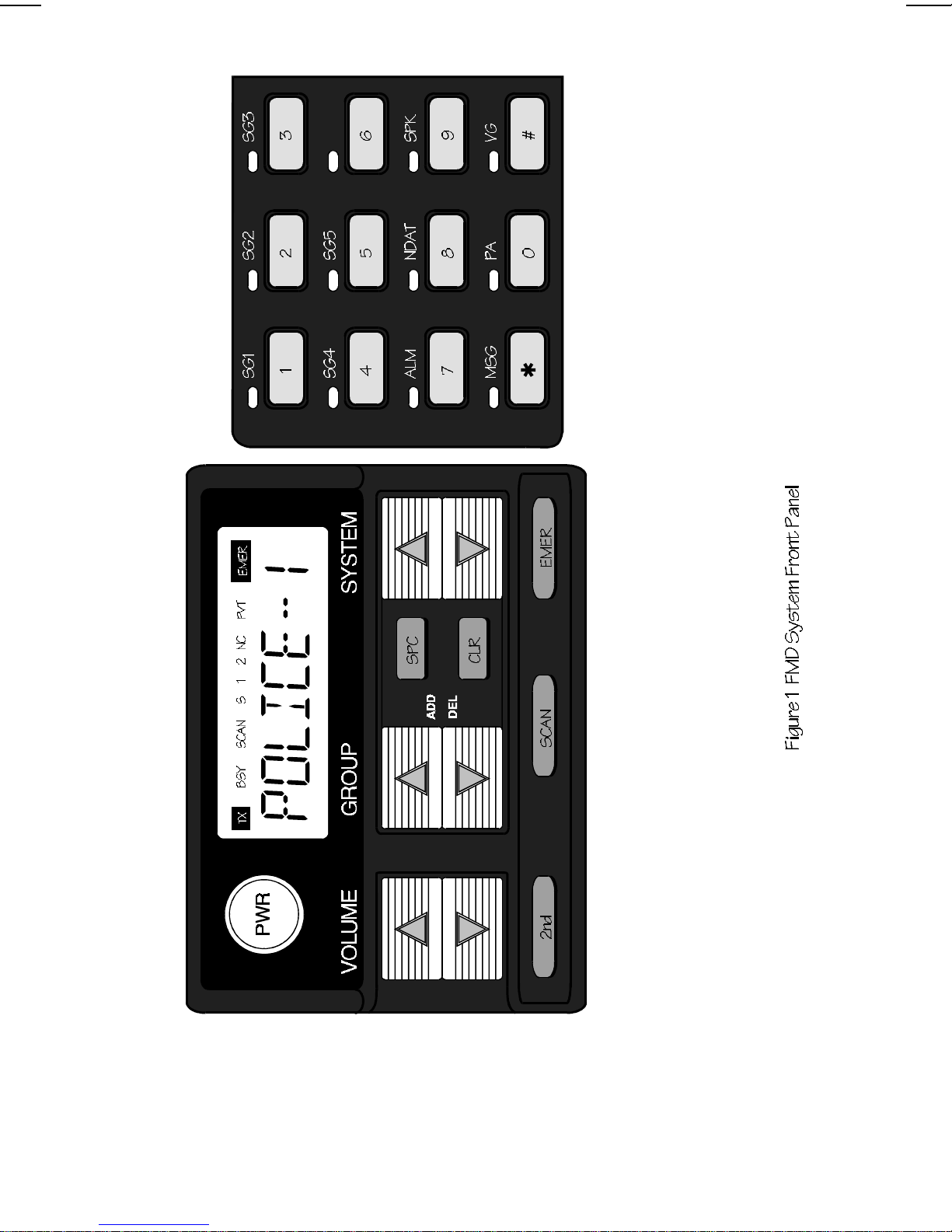
CONTROLS, INDICATORS, AND DISPLAYS
The FMD System radio contains twenty four switches, an eight
character alphanumeric display, nine indicators, and twelve LEDs. In
addition, there are times when partof the eight character display willbe
used to display the radio status.
A layout of the FMD front panel is shown in Figure 1.
CONTROLS
PWR
Momentary switch. Press once to turn on the radio.
Push again to turn off the radio.
VOLUME
Twomomentary switches (auto ramping).
VOLUMEUP
and
VOLUMEDOWN
. Beepsareheardwhilestep-ping
the volume when no call is in process. Hold the switch
(up or down) to auto ramp the volume.
SYSTEM
Two momentary switches (auto ramping). The
SYS-
TEM UP
and
SYSTEM DOWN
switches are used to
select system changes. The alphanumeric name of the
system will appear without changing systems the first
timeeither
SYSTEM
switch is pressed. (Note: the radio
may be programmed with wrap around on the system
selection; this would allow the radio to switch from the
highest to lowest system with one change instead of
wrapping all the way through the list).
4
5

GROUP
Two momentary switches (auto ramping). The
GROUP
UP
and
GROUP DOWN
switches are used to select the
current group/channel selection. (See wrap around
note from SYSTEM.)
SPC
Momentary switch. The
SPC
(Special Call) switch is
used to enable special call mode if programmed in the
radio. Special Calls are used to place telephone inter-
connect calls and individually call other radios.
CLR
Momentary switch. The
CLR
switch is used to restore
the radio to normal group operation (e.g. exit Special
Call), monitor a conventional channel.
2nd
Momentary switch. The
2nd
switch is used to select the
functions of the DTMF keypad.
SCAN
Momentary switch. The
SCAN
switch is used to toggle
scan on and off. When on, the SCAN indicator in the
display will be on (note: The radio may be programmed
to disable scan when the microphone is off hook. If so
programmed, the radio will not scan when the micro-
phone is off hook, but SCAN remains on indicating the
state you have selected for normal operation.) The
SCAN
switch is also used in conjunction with the
GROUP
Up and Down switches to perform the Add and
Delete functions.
EMER
Momentary switch. The EMER switch may be pro-
grammedto send anEmergency messageand/orselect
a home group/channel.
INDICATORS
TX
ON indicates the radio is transmitting.
BSY
Lights when a group is active (trunked system) or when a chan
-
nel is busy (conventional system). Flashes when a callis queued
on a trunked system.
SCAN
ON indicates that the user has enabled the Scan function.
S 1 2
Priority level for Scan:
S
indicates that the displayed
group/channel is enabled for scan.
2
indicates that the conven
-
tional channel is set for priority 2.
1
indicates that the conven
-
tional channel is set for priority 1.
6

NC
ON indicates that the radio cannot locate a trunked
system. This indicates that the radio is not functional for
voice or data communications. FLASHING indicates
that the radio is operating in trunked failsoft mode and
some of the features of the system may not be available
for use (e.g. Telephone Interconnect).
PVT
ON indicates that the radio has been set to transmit in
Voice Guard encrypted mode (Note: must have a Voice
Guard module attached to the radio for this indicator to
work).
EMER
ON indicates that the radio has declared an Emergency
on the system (may beprogrammed to notdisplay when
declaring emergencies). FLASHING indicates that an-
other radio on the displayed group has declared an
emergency.
KEYPAD LEDs
The twelve switch keypad is a programmable keypad with multiple
layers of functions: DTMF keypad, User Programmable Options, and
Status operation. These functions are accessed via Special Call or the
2nd key. The Primary keypad (typically the User Programmable Op-
tions) is the one which uses the twelve LEDs (one above each switch).
The following functions will cause the corresponding LED above its key
to light: External Alarm Active, Mobile Data disabled, External Speaker
selected, Message mode, Public Address active, or Voice Guard Pri-
vate mode.
DISPLAYS
The radio is capable of displaying status messages in the alpha
display. Some of these messages will use the entire display while
others will use two characters. When the short message is displayed
it may be on the right or left of the display. It is separated from the
normal information with an indicator such as an asterisk ("*").
Full Length Indicators
**INDV** Displayedwhenyourunitreceives anindividualcallfrom
another unit.
7

ID ##### If programmed, displayed when your unit receives an
individual call where ##### is the unit id of the calling
radio (Note: If the ID is in your Special Call list, it may
show an 8 character name instead of the number).
GR ##### If programmed, displayed when acall is received to your
selected group where ##### is the unit ID of the calling
radio (Note: If the ID is in your Special Call list, it may
show an 8 character name instead of the number).
PHN CALL Displayed when your radio receives a telephone call
from the trunked system.
DATACALL Displayed when your radio is involved in a data call.
*NO DATA Displayed when your radio is in the data disabled state.
ALL CALL Displayed when receiving a System wide call.
*AGENCY* Displayed when receiving an Agency Call.
*FLEET* Displayed when receiving a Fleet Call.
PRIMARY Displayed when using 2nd to select primary keypad
operation.
ALTRNATE Displayed when using 2nd to select alternate keypad
operation.
KEYPAD Displayed when using 2nd to select DTMF from the
keypad in conventional mode or in Special Call mode.
Abbreviated Indicators
C Displayedwhenanindividualcallhasbeenreceivedand
not answered. By selecting Special Call, the call can be
recalled for return at a later time (Note: the call is not
saved through a power cycle and the ID is cleared by
pressing the CLR switch).
8

ALERT TONES
The FMD mobile generates a number of alert tones to indicate its
current state. These tones are described below:
CALL ORIGINATE
A short tone is sounded whenever you key the microphone Push-
To-Talk (PTT) switch and the radio has acquired a channel. This tone
indicates that you may proceed to talk (both conventional and trunked
operation).
CALL QUEUED (Trunked Operation Only)
If your hear one short, high pitched beep after you key the micro-
phone, this indicates that the system has placed your request in a
queue. The tones are sounded at both your transmitting unit and your
receiving unit(s), indicating to the user on the receiving end that they
will receive a call shortly. If you should unkey the microphone while in
queue, your radio will autokey when a channel becomes available
(Automatically key (push-to-talk), see AUTOKEY below).
AUTOKEY (Trunked Operation Only)
When you key the microphone to place a call on the system and
release the PTT switch before getting to the channel (e.g. a queued
call), the radio will automatically key on the channel when it gets the
assignment. The radio will generate a long beep and hold the transmit-
ter keyed for two seconds. Press the PTT switch to keep the channel
and send your message before this two second timeout has expired.
SYSTEM BUSY (Trunked Operation Only)
If you key the microphone and hear three short, medium pitched
beeps, this indicates that the receiving party is already on the system
or the system is busy and its queue is full. You must rekey later to
access the system.
CALL DENIED (Trunked Operation Only)
If you hear a single low pitched tone when you key the microphone,
your request has been denied by the system. This will happen if you
are an invalid user or if you are requesting an unavailable service.
9

OUT OF RANGE/SYSTEM INOPERATIVE (Trunked Operation
Only)
If you hear a single low pitched tone immediately after you key the
microphone, this indicates your mobile unit is out of range of the
repeater. Your radio will try to place the call for a short period after the
initial attempt. The radio willgenerate a second low pitched beep when
it gives up trying to place the call. If you hear these beeps when you
know you are in calling range, this indicates that the system is off the
air, or that your mobile unit needs servicing. When the mobile is out of
range, the NC indicator will be displayed.
CARRIER CONTROL TIMER
The Carrier Control Timer alert is a low pitched tone you will hear
whenever you have kept the PTT switch continuously pressed for a
preprogrammed length of time. The transmitter will shut down when
the steady low pitched tone starts, interrupting communications. When
on a trunked system, the FMD will generate short beeps prior to
unkeying to alert you that the transmission is about to be terminated.
To maintain communications, release and re-key themicrophone. This
resets the timer and turns the transmitter back on. The CCTis a built-in
precaution against inadvertent use of the system.
OPERATING NOMENCLATURE
CONVENTIONAL OPERATION
All radios on a conventional system operate in one of two modes:
repeatedortalk-around. Talk-around(alsoreferredtoas"directmode")
provides a direct radio-to-radio short-range communications link. It is
intended to maintain communications outside of the main system
coverage area. Trunked features (such as call queueing and system
scan) are not available in conventional mode.
TRUNKED OPERATION
Trunked operation refers to the use of a set of radio frequency
channels by multiple user groups. By using high speed digital signal-
ling, users may place and receive calls to single or multiple users
without being monitored by other users (or groups) on the system.
10

SYSTEM - (Trunked Operation Only)
The term system refers to the particular group of station repeaters
and set of group/special calls providing service to the radio. Radios
can be preprogrammed to work in different systems by changing the
System selection or through wide area roaming.
GROUP OR SUBFLEET (Trunked Operation Only)
A group of users share the same preprogrammed group identifica-
tion number in their radios. All radios in the same group will receive a
dispatch call placed by any one radio in the group.
FLEET (Trunked Operation Only)
A fleet of users consists of multiple groups (subfleets). Radios can
be preprogrammed to make fleet calls to simultaneously access multi-
ple user groups.
AGENCY (Trunked Operation Only)
An agency is composed of multiple fleets. Radios can be prepro-
grammed to initiate agency calls to access multiple fleets.
INDIVIDUAL CALL (Trunked Operation Only)
Every radio in the system has been assigned a preprogrammed,
unique individual identification code. A radio may be programmed to
individually call another particular radio using Special Call.
WIDE AREA SYSTEM OPERATION (Trunked Operation Only)
This function applies when your systems are networked together in
a multi-site configuration. In this mode, your calls are automatically
routed to the proper systems. You may notice a delay when you press
the PTT switch while the system is connecting the correct sites. The
BSY indicator may be on to indicate that you are on the voice channel.
When in the multi-sited mode, your radio may be programmed to
look for alternate systems when you go out of range of the currently
selected system. If analternate system is found, theradio will lock onto
thatsystem andautomatically select thecorrect informationforthisnew
system. Alternately, the radio may be programmed to revert to a
conventional channel when out of range of the trunked system.
11

Each trunked system may also have a priority trunked system
associated with it. When set to a system with that priority system
programmed, the radio will check for the priority system periodically. If
found, it will automatically switch to that system. The timer is reset
every time the PTT switch is pressed to avoid interrupting a conversa-
tion.
TELEPHONE INTERCONNECT (Trunked Operation Only)
This feature allows you to initiate or receive telephone calls through
your radio if the system is configured for this operation.
OPERATING THE RADIO
TURNING THE RADIO ON
1.
Push the PWR switch. The display will show the group alpha name once
power up is complete. When powering up, the last selected Group or
Channel should be displayed unless the radio is programmed for a pre
-
programmed power up System/Group. On radios with Multi-site fea
-
tures enabled, the radio will automatically log onto the system once
power up is complete.
2.
Set the volume using the VOLUME UP or DOWN keys. A short beep will
sound to show each volume level step. The beeps will not sound if a call
is being received.
SELECTING SYSTEM/GROUP/CHANNEL
Use the GROUP, SYSTEM, or SG1-SG5 controls to select a differ-
ent Group, System, or Channel.
Group Selection:
Press the GROUP Up/Down switches until the desired Group
nameappearsinthe alphanumericdisplay. Atone willbeheard
each time the Group name changes. On units with Automatic
Login for Multi-Site Operation, the radio will transmit briefly after
a Group change.
To select a differentchannel when you have selected a conven-
tional system:
Press the GROUP Up/Down switches until the desired Channel
nameappears in the alphanumeric display. Atone willbeheard
each time the channel name changes unless the BSY indicator
is on.
12

System Selection:
Press either SYSTEM switch to bring up the currently selected
system. Press and hold that SYSTEM switch until the desired
System selection appears.
System-Group Selection:
Assuming the SG1-SG5 functions are mapped to the primary
keypad and the primary keypad is selected, simply press and
release one of the System-Group keys. When pressed, a beep
will sound if the System/Group changes. The display will indi-
cate the new System and Group.
ADJUSTING SQUELCH (CONVENTIONAL)
The squelch may be adjusted on in conventional (non-trunked)
operation as follows:
1. Press and hold the SCAN switch while pressing the SYSTEM
UP switch until the BSY indicator is on continuously. Noise will
be heard in the speaker if optional Channel Guard is not
enabled.
2. Press and hold the SCAN switch while pressing the SYSTEM
DOWN switch until the BSY indicator goes off.
3. Release the SCAN switch.
ADJUSTING BACKLIGHT LEVEL
The level of the backlighting for the LCD may be adjusted as
follows:
1. Press and hold the CLR switch.
Pressing the CLR switch disables the squelch on
conventional channels. You may want to reduce the
volume before setting the backlight level to prevent
excessive noise in the speaker.
NOTE
13

2. Press the GROUP UP or DOWN switches until thedesired level
of backlighting (off, low, medium, or high) is obtained.
3. Release the CLR switch. The backlight level is stored when the
radio is turned off.
TRUNKED OPERATION
RECEIVING A TRUNKED DISPATCH CALL
1. Press the VOLUME UP or DOWN switches and listen for the
desired level of audio tone.
2. Select the System and Group you wish to monitor. The radio
will now receive calls directed to the selected System and
Group. If an individual call is received, theindividual call display
will appear.
PLACING A TRUNKED DISPATCH CALL
To send a message on a trunked system, proceed as follows:
1. Select the System and Group you wish to transmit on.
2. Press and hold down the PTT switch.
3. You will hear a short beep indicating that you have access to
the system. When you hear the beep, you can begin your
message. (NOTE: If you hearmorethanonetoneoralowpitch
tone, the system may be busy, your request has been placed in
queue, or your call request has been denied for some reason.
Refer to the ALERT TONES section for more details.)
If PTT is released before the channel available tone, the
channel available tone will be extended. The radio will
Autokey for two seconds, allowing time for you to press the
PTT switch and talk.
Groups may be programmed as receive-only. If a group is
receive-only, nothing will happen when the PTT switch is
pressed.
NOTES
14

4. After you have finished your call, releasing the PTT switch ends
the call automatically.
CONVENTIONAL MODE OPERATION
RECEIVING A CALL
1. Make sure that the radio is turned ON, and the proper channel
is selected using the GROUP UP/DOWN and SYSTEM
UP/DOWN switches.
2. Press the CLR switch to monitor the channel. Noise will be
heard if there is no activity on the channel. This function is also
useful for setting the desired Volume level.
3. You will hear the voice message automatically if a valid mes-
sage is received by your radio.
SENDING A MESSAGE
1. Make sure the radio is turned ON, and the proper Channel and
System have been selected.
2. Press the CLR switch to determine if the channel is in use.
Never transmit a message with your radio while the channel is
being used by someone else.
3. Press the PTT switch and speak into the microphone after the
channel acquisition alert.
4. Release PTT when you are finished.
CONVENTIONAL FAILSOFT OPERATION
In the unlikely event of a failure of the trunked system communica-
tions may take place in conventional failsoft mode. Your radio will be
automatically directed to a communications channel set up for this
purpose. During this mode of operation, your control unit will display
"CONV FS" in the alphanumeric display and the NC indicator will flash.
You will notice increased activity on your channel during conventional
failsoft operation, so be careful not to transmit until the channel is clear.
Operation during conventional failsoft will be the same as operation
on a conventional system, except that it will not be possible to select a
15

communications channel, or use emergency or special call. When
trunking is restored, you will automatically be returned to normal opera-
tion.
EMERGENCY OPERATION
RECEIVING AN EMERGENCY MESSAGE
From the Selected Group
Whenyoureceivean emergency call fromamemberoftheselected
Group and System, the EMER Icon will flash, the BSY Icon will light,
and a tone will be heard. Follow your standard emergency procedures.
The EMER indicator will flash until the emergency is cleared or your
radio scans into a non-emergency call.
From a Scanned Group
When you receive an emergency call from a scanned Group (scan
operating), the display will flash the name of the Emergency Group, the
EMER Icon will flash, and a tone will be heard. The EMER Icon will
flash while the voice channel is active.
SENDING AN EMERGENCY MESSAGE
To send an Emergency call to the selected (or Home) Sys-
tem/Group, proceed as follows:
1. Press and release the EMER switch (holding it pressed for
approximately one second) or activate the external emergency
switch. The EMER indicator will show continuously (unless
programmed off). A message will be sent to the dispatcher with
your ID to declare an emergency. You will be given highest
priority for voice communication.
2. Press the PTT switch and wait for the channel-available tone.
Speak into the microphone in a normal voice. All audio and
displays will be restored to normal.
Emergency and Special Call are not operational during
conventional failsoft. Also, the GROUP control will notoperate.
NOTE
16

3. Release the PTT switch when the transmission is completed,
and listen for any reply. The TX indicator will go out when you
release the PTT switch.
CLEARING AN EMERGENCY
If your radio has been programmed as a supervisory unit, you may
clear emergency calls. When the emergency is no longer in effect, the
emergency call may be cleared as follows:
1. Press and hold the CLR switch.
2. Press and release the EMER switch. The EMER indicator will
go off.
3. Release the CLR switch.
SPECIAL CALLS (Trunked Operation Only)
TheSpecialCallfeatureallowsyoutomakecallstoindividualradios,
telephone interconnect calls, and/or System All Calls.
PLACING A TELEPHONE INTERCONNECT CALL
TheTelephoneInterconnectfeatureisonlyavailableonsysemswith
interconnect hardware.
1. Make sure the radio is turned ON, and the proper System has
been selected. Press the SPC switch until the Special Call
name appears in the display. Press the GROUP Up/Down
switches until the desired name appears in the display.
2. Press the PTT switch momentarily and release.
3. The radio automatically transmits the preprogrammed number
stored in the radio’s memory. The system will then dial the
number and the ringing tone will be heard and the radio. When
the landline party answers, you may speak to them by pressing
thePTTswitchand talking. IftheselectionisforDTMFoverdial,
thesystem willrespondwitha pseudo dialtone. Whenyouhear
the dial tone, proceed with step 4.
4. Once you hear the dial tone, use the DTMF microphone (op-
tional) to dial the desired number. When you have finished
17

dialing, press the "*" key on the DTMF keypad to tell the system
to dial the number.
Your FMD radio is capable of simplex (one way)
conversation only. The person you are talking to can hear
you ONLY when you have the PTT switch pressed. You
can hear the person on the telephone ONLY when the PTT
switch is released.
IfyouleavethePTTswitchreleasedfortoolong,thesystem
will send three beeps. When you hear these beeps, you
have five seconds to press the PTT switch before the call
is automatically terminated.
NOTES
18

5. Toterminatethecall,momentarilypresstheCLRswitchorhang
up the microphone.
RECEIVING A TELEPHONE INTERCONNECT CALL
1. Receiving a telephone interconnect call is identical to receiving
an individual trunked dispatch call (see RECEIVING A
TRUNKED DISPATCH CALL section). When the telephone
call is received, the radio will display "PHN CALL".
2. Toterminatethecall,momentarilypresstheCLRswitchorhang
up the microphone.
3. If you were out of the vehicle when the call came in, the display
will show "C*" or "*C" to indicate that a call was received.
PLACING AN INDIVIDUAL CALL
1. Make sure the radio is turned ON, and the proper System has
been selected. Press the SPC switch until the Special Call
name appears in the display. Press the GROUP Up/Down
switches until the desired name appears in the display.
2. Press the PTT switch and wait for the channel available tone
before talking.
3. When completed, release the PTT switch and listen for any
reply.
4. When your call is finished, press the CLR switch or return the
microphone to the hookswitch. The previously selected Group
name will appear on the display.
RECEIVING AN INDIVIDUAL CALL
WhenyoureceiveanIndividualCall(calldirectedonlytoyourradio),
the display will change to one of the following displays:
1. "* INDV *"
2.
"ID xxxxx",
where xxxxx is the numeric ID of the calling radio.
3.
" ALPHA ",
where ALPHA is the alpha name of the calling radio.
19

Receiving an Individual Call will also cause the BSY indicator to turn
on. After the transmission, the BSY indicator will go out. The display
will continue to show the above until the predefined timeout for calling
backexpires. Duringthecallbackperiod,pressthePTTswitchtoreturn
the call. If the call is not returned before the time has expired, the
display will return to the Group display with a "C*" at the left side or a
"*C" at the right side of the display. This indicates a call has been
received. The id may be recalled by pressing SPC. While the display
shows the ID, pressing PTT will allow calling back the originating party.
Pressing CLR will cause the call display to go out and the ID to be
erased.
GROUP SCAN OPERATION
You may program your radio to scan a number of Groups or
Channels for activity.
ADDING/DELETING TO/FROM SCAN
To add a Group/Channel to Scan
1. Press the SCAN switch if the SCAN Icon is on, to turn scan off.
2. Select the Group or Channel to be added to Scan using the
Group switches.
3. Press and hold the SCAN switch. While holding SCAN switch
press the GROUP UP to add the group or channel to scan. The
S indicator will be displayed. In conventional mode, to select
priority channels, press the GROUP UP switch again to select
priority 2 (the S indicator will go outand the 2 indicator will come
on). To select priority 1, press the GROUP UP switch a third
time (the 2 indicator will go out and the 1 indicator will come on).
1. Theradiowillrememberthescanstatethroughapower
cycle unless programmed with a predefined power up
state.
2. The radio may be programmed to stop scanning when
the microphone is removed from the hookswitch.
NOTES
20
Table of contents
Other Ericsson GE Radio manuals


