Ritron RBS-477DMR User manual

Have questions? Call 800-872-1872 or visit our website at www.ritron.com
Professional Two-Way DMR/Analog Base Radio
RBS-477DMR Base Radio User Manual
•DMR Digital, Conventional Analog
•Narrow Band Capable
•20 DMR or Analog Channels
•2.5 Watt Transmit Power
•1 Watt Audio Output
NOTICE: The RBS-DMR-PCPK PC programming software kit is
required to program channel frequencies and other settings.
Please contact your Authorized Ritron Reseller.
Contents Page
INTRODUCTION
Factory Default Frequencies & Settings ..................1
Optional Replacement Accessories.........................1
Basic Features .........................................................2
Items Included with the Base Radio.........................2
Exposure to Radio Frequency Energy.....................3
Observe Caution in the Following Environments.....3
RADIO OPERATION -GENERAL
Radio Controls and Connectors...............................4
On-Off Volume Adjust .............................................. 5
Channel Selection....................................................5
P2 Button..................................................................6
Channel Scan Operation..........................................8
RADIO OPERATION –ANALOG CHANNELS
Receive – Analog Channels.....................................9
Transmit – Analog Channels.................................... 9
QC and DQC Tone Codes – Analog Channels........9
Paging Decode Operation – Analog Channels......10
P1 Operation – Analog Channels...........................10
Contents Page
RADIO OPERATION –DMR CHANNELS
DMR Channel Overview.........................................11
Receive – DMR Channels ......................................11
Transmit – DMR Channels .....................................12
P1 Button – DMR Channels....................................12
SPECIFICATIONS
General...................................................................13
Receiver..................................................................13
Transmitter..............................................................14
RPS-1B Power Supply............................................14
General Features....................................................14
Channel Features ...................................................15
Analog Paging Decode...........................................15
FCC AND IC LICENSE REQUIRED
FCC Licensing ........................................................16
How to Obtain and FCC License............................16
Industry Canada Regulations .................................16
Safety Standards....................................................16
Service....................................................................16
RITRON WARRANTY INFORMATION................................17
Ritron Pub. 14500106 Rev. A12/22
© 2022 Ritron, Inc. All rights reserved. Ritron, Jobcom, OutPost, GateGuard, Quiet Call and Quick Assist
are registered trademarks of Ritron, Inc. Quick Talk, Liberty and RadioNexus are trademarks of Ritron, Inc.
Call 800-USA-1-USA (800-872-1872)
For the right Wireless Solutions for your communication needs.
P.O. Box 1998 ·Carmel, Indiana 46082-1998 · Ph: 317-846-1201 · Fax: 317-846-4978
Email: ritron@ritron.com · www.ritron.com

RBS-477DMR DMR/ANALOG BASE RADIO USER MANUAL INTRODUCTION
Have questions? Call 800-872-1872 or visit our website at www.ritron.com 1
Dear Valued Ritron Customer,
Thank you for your purchase of the RBS-477DMR DMR/Analog base radio. Each radio comes pre-programmed with the 2 factory
default channels listed below. Channel programming can be changed via the RBS-DMR-PCPS PC programming software and
cable.
If your company currently has an FCC license on frequencies different from the default frequencies, the radio can be PC
programmed to custom frequencies using optional Ritron RBS-DMR-PCPS PC programming software, other settings can also be
configured. Please contact your Ritron Reseller for information on “custom” radio programming services.
Please be advised that operation on the factory default frequencies require that you obtain an FCC Operator License
BEFORE USE.
FACTORY DEFAULT FREQUENCIES AND SETTINGS
RBS-477DMR Factory Default Frequency Settings – Operating Band 450-470 MHz
Channel TX/RX Color Code/ Destination ID/
Channel Type Frequency (Table) Tone Freq. RX Group ID TX Contact TX Power
CHAN 1 Analog 467.850 MHz (26) No Tone - - 2.5 Watts
CHAN 2 DMR 467.850 MHz (26) Color Code 1 1001 - Group 1001 - Group 2.5 Watts
16777215 – All Call
Analog = Narrow Band (12.5 KHz)
DMR Radio ID (SUID) = 1
O
PTIONAL
R
EPLACEMENT
A
CCESSORIES
TO ORDER CALL 800-USA-I-USA
AFB-1545....Molded Flex, Dual-band Replacement Antenna
RAM-I545....Magnet-mounted, Dual-band Antenna w / BNC
RPS-IB ........Replacement 110 VAC Power Supply
CCL-M.........12 VDC, Cigarette Lighter Adaptor
JBSK-I2.......12 VDC, Adaptor Kit
RHD-4X.......Dual Ear Headset
RHD-6X.......Lightweight Behind-the-head Earset w / In-line PTT
RHD-8X.......Lightweight Earbud w / mic and In-line PTT
RSM-3XA ....Remote Speaker Microphone
RM-7............Hand Microphone & Hang-up Bracket
RSP-5..........External Speaker w / 5 Watt Audio Capability
JBS-MMK....Mobile Mounting Kit
(Does not include screws to mount bracket to wall or vehicle)
Call RITRON for a complete listing.
JBSK-12 RHD-6X
12-Volt Adapter Kit Behind the Ear Headset
RHD-8X
Single Earbud RAM-1545
Magnet-Mounted
Dual-band Antenna
RSP-5 RM-7
5-Watt External Speaker Hand Microphone

RBS-477DMR DMR/ANALOG BASE RADIO USER MANUAL INTRODUCTION
Have questions? Call 800-872-1872 or visit our website at www.ritron.com 2
BASIC FEATURES
This manual covers Ritron RBS-477DMR DMR/Analog base radio. A rugged,
programmable two-way desktop base radio designed to operate in a professional FM
communications band. Each radio is equipped with these features:
• Analog and DMR Digital Mode Operation.The RBS-477DMR DMR/Analog base
radio can operate in Analog and DMR Digital mode within the 450-470 MHz
frequency band.
• Push-button Operating Controls. The Push-To- Talk (PTT), Channel, On / Volume
Up, Volume Down / Off; and the special feature P1 and P2 button controls are
conveniently located on the face of the radio.
• 16 Character LCD Display. A backlit, 2-line x 8-character, LCD display will show
the channel, volume, and many current operating conditions.
• 20-Channel Capability. Up to 20 channels can be programmed to contain a unique
set of operating frequencies and options. Each channel can be programmed for
Analog or DMR Digital operation; and can be given an 8-character name that will be
shown on the top line of the LCD display.
• QC (Quiet Call) and DQC (Digital Quiet Call) Interference Eliminator Codes.
Each Analog channel can be programmed from a list of 50 QC sub-audible or 104
DQC digital privacy codes.
• 48 DMR Contacts. The base radio can be programmed with up to 48 DMR Group or
Individual contacts. Each DMR channel can be programmed to receive any number
of the Group contacts, and the P1 button can be assigned any number of the Group
or Individual contacts for transmit. Each DMR Contact can be given an 8-character
name that will be shown on the bottom line of the LCD display when received, or
when selecting with the P1 button for transmit.
• 20 DMR RX Groups. Each DMR channel can be programmed to receive any
number of Group Contacts from the 48 DMR Contacts, and can therefore be
considered an RX Group.
• 10 Analog Contacts. The base radio can be programmed with up to 10 Analog 2-
Tone, DTMF or Selcall contacts. Each Analog channel can be assigned any number
of the Analog Contacts, which are selected by the P1 button for transmit. Each
Analog Contact can be given an 8-character name that will be shown on the bottom
line of the LCD display when selecting with the P1 button for transmit.
• Channel Scanning. Channel Scan allows scanning of all 20 channels programmed into the radio. Each channel can be
removed from the scan list through PC programming. Scan operation has many features, including Priority Scanning and Busy
Channel Blocking.
• P1 Button. The P1 Button is used to select DMR Contacts for transmission on DMR channels, and to select Analog Contacts
for transmission on Analog channels. The Contacts available for P1 selection are programmed on a per channel basis.
• P2 Button. The P2 Button can be programmed to initiate Channel Scan, Monitor the channel, go to the last channel that
received a signal, or send a Call Tone. It can also be set to send a 2-Tone, DTMF or Selcall ANI on Analog channels, and
send a DMR contact on DMR channels.
• 2-Tone, DTMF or Selcall Decode. Each Analog channel can be programmed for 2-Tone paging decode within a frequency
range of 300-1500 Hz, or for a 3-9 digit DTMF or Selcall decode. Additional paging decode features include Group Call, All
Call, automatic reset, and transpond alert.
• DTMF or Selcall ANI. Each Analog channel can be programmed to transmit a unique DTMF or Selcall ANI string on each
transmission.
• Alert Tones. Each channel is programmable for a variety of alert tones that include RX courtesy beep, TX clear to talk beep,
busy channel lockout alert, last active channel marker, and channel scanning indicator.
• Always On Operation.The radio can be set to automatically turn-on any time power is applied to the radio.
RBS-477DMR DMR/Analog
Base Radio
RPS-1B
12V Power Supply
AFB-1545 Antenna
Items included with the
Base Radio

RBS-477DMR DMR/ANALOG BASE RADIO USER MANUAL INTRODUCTION
Have questions? Call 800-872-1872 or visit our website at www.ritron.com 3
EXPOSURE TO RADIO FREQUENCY ENERGY
These products generate radio frequency (RF) energy when the PTT button on the front of the unit is depressed. The product has
been evaluated for compliance with the maximum permissible exposure limits for RF energy at the maximum power rating of the
unit when using antennas available from RITRON. Antennas other than those mentioned below have not been tested for
compliance and may or may not meet the exposure limits at the distances given. Higher gain antennas are capable of generating
higher fields in the strongest part of their field and would, therefore, require a greater separation from the antenna.
AFB-1545 (included with radio) -2 dBi gain
RAM-1545 (optional magnet-mount antenna) 2 dBi gain
RBS-477DMR:
Using the AFB-1545 antenna (included with the product) in a vertical orientation at the 20 cm (7.9 inches) minimum expected
separation distance and greater, the maximum RF exposure is well below the General Population/Uncontrolled limits. When using
the RAM-1545 (optional magnet-mount antenna with 25’ cable) in a vertical orientation a 29.4 cm separation distance is required.
Antennas other than those available from RITRON have not been tested for compliance and may or may not meet the exposure
limits at the distances given. Higher gain antennas are capable of generating higher fields in the strongest part of their field and
would, therefore, require a greater separation from the antenna. This product is not to be used by the general public in an
uncontrolled environment unless compliance with the Uncontrolled/General Population limits for RF exposure can be assured.
En utilisant l'antenne AFB-1545 (fournie avec le produit) dans une orientation verticale à la distance de séparation minimale prévue
de 20 cm (7.9 pouces) et plus, l'exposition RF maximale est bien inférieure aux limites de la population générale / non contrôlées.
Lors de l'utilisation de la RAM-1545 (antenne optionnelle à montage magnétique avec câble de 25 pi) dans une orientation verticale,
une distance de séparation de 29.4 cm est requise. Les antennes autres que celles disponibles chez RITRON n'ont pas été testées
pour leur conformité et peuvent ou non respecter les limites d'exposition aux distances indiquées. Les antennes à gain plus élevé
sont capables de générer des champs plus élevés dans la partie la plus forte de leur champ et nécessiteraient donc une plus
grande séparation de l'antenne. Ce produit ne doit pas être utilisé par le grand public dans un environnement non contrôlé, à moins
que le respect des limites d'exposition aux RF pour la population non contrôlée / générale ne puisse être assuré.
To limit exposure to RF energy to levels below the limit, please observe the following:
• Use only the antenna(s) available from RITRON for these models. DO NOT operate the radio without an antenna.
• DO NOT transmitter more than 50% of the time.
• When transmitting, make certain that the distance limits for the particular model in use are observed.
• DO NOT allow children to operate the radio.
When used as directed, this series of radios is designed to comply with the FCC and IC RF exposure limits for
“Uncontrolled/General Population”. In addition, they are designed to comply with the following Standards and Guidelines:
• United States Federal Communications Commission, Code of Federal Regulations; 47 CFR §§ 2 sub-part J.
• American National Standards Institute (ANSI) / Institute of Electrical and Electronic Engineers (IEEE) C95. 1-1992.
• Institute of Electrical and Electronic Engineers (IEEE) C95.1-1999 Edition.
Copyright Telecommunications Industry Association
OBSERVE CAUTION IN THE FOLLOWING ENVIRONMENTS TO MAXIMIZE THE LIFE OF YOUR RADIO EQUIPMENT
LOCATION: Be aware that this radio and / or antenna may create interference with, or be interfered with, by nearby electronic
equipment such as computers, monitors, keyboards, electronic telephones and other sensitive devices. Either move the equipment
or use a remote antenna to separate components sufficiently to stop or reduce interference.
MOISTURE: Ritron base radios are not waterproof. DO NOT directly expose them to rain or excessive moisture.
CHEMICALS: Detergents, alcohol, aerosol sprays or petroleum products can damage the radio case. DO NOT use petroleum
solvents of any kind; use a soft cloth moistened with water to clean the case.
EXTREME HEAT: High temperatures can damage the radio and its components. DO NOT expose the units to extreme heat or
leave them in direct sunlight.
EXCESSIVE TRANSMISSIONS: DO NOT hold the Push-To-Talk switch down longer than necessary during transmission intervals.
VIBRATION / SHOCK: Although your Ritron base radio is designed to be rugged, it will not survive excessive abuse. Avoid
dropping the radio.

RBS-477DMR DMR/ANALOG BASE RADIO USER MANUAL RADIO OPERATION -GENERAL
Have questions? Call 800-872-1872 or visit our website at www.ritron.com 4
R
ADIO
C
ONTROLS AND
C
ONNECTORS
1 ANTENNA
The flexible antenna radiates and receives radio signals.
The antenna connects to a BNC type connector located on
the top end of the radio.
NOTE: The AFB-1545 antenna included with the radio will
work with VHF and UHF radios.
2 VOLUME DOWN / OFF BUTTON
Press and release the Volume Down / Off button to
decrease volume. The channel display will indicate the
volume level when the Volume Down / Off button is
pressed. To turn Off the unit decrease the volume level to
“0”, then press an additional time to turn off. The speaker
will sound a double beep.
3 ON / VOLUME UP BUTTON
To turn the unit On, press and release the On / Volume Up
button; the speaker will sound the Channel Beep. Once
the radio is On, press and release this button to increase
volume. The channel display will indicate the volume level
when the On / Volume Up button is pressed.
4 PUSH-TO-TALK (PTT) BUTTON
Press and hold the PTT when transmitting; release it to
receive.
5 AUDIO ACCESSORY JACK
The audio accessory jack is used to plug in earphone
options and, in conjunction with the microphone jack, to
connect an optional remote speaker / microphone or a
single-ear or dual-ear headset.
6 MICROPHONE JACK
The microphone jack is used to connect optional external
microphones and, in conjunction with the audio accessory
jack, to connect an optional remote speaker / microphone,
or a single-ear or dual-ear headset.
7 USB PROGRAMMING JACK
USB Mini B jack used for radio programming.
8 CHANNEL SELECTOR BUTTON
Press the Channel Selector button and the radio will
advance the channel. The Channel Beep will be heard any
time Channel 1 is selected.
9 P1 BUTTON - PROGRAMMABLE SOFT KEY
The P1 Button is used for selective signaling. Use the P1
button to step through DMR or Analog contacts for
selective calling or control signaling.
10 P2 BUTTON - PROGRAMMABLE SOFT KEY
The P2 Button is capable of performing a variety of
functions. Function options: Channel Scan, Weather
Channel, Monitor, Send 2-Tone Code, Send Call Tone,
Send DTMF or Selcall ANI. Refer to the P2 Button section
of this manual for details.
FIG-1: RADIO CONTROLS & CONNECTORS
11 CHANNEL DISPLAY
The 2-line x 8-character channel display will indicate the
current operating channel when in standby. The display
will also indicate current operating conditions such as
volume, caller ID, DMR/Analog channel type, busy
channel, etc.
12 MICROPHONE
The microphone allows your voice to be heard in
transmissions to other radios. Speak in a normal tone;
shouting does not improve your listeners’ reception. With
an optional headset or hand mic plugged into the
Microphone Jack this front panel microphone is disabled.
13 SPEAKER
The speaker allows you to hear calls on your channel.
With an optional headset or hand mic plugged into the
Audio Accessory Jack this front panel speaker is disabled.
14 POWER CONNECTOR (TOP END OF CASE)
The power connector on the top end of the radio is used to
connect power to the unit, either an external 12 VDC
supply or the RPS-1B cube power supply included with the
radio.
1
5
6
7
9
8
10
11
12
13
14
4
2
3

RBS-477DMR DMR/ANALOG BASE RADIO USER MANUAL RADIO OPERATION -GENERAL
Have questions? Call 800-872-1872 or visit our website at www.ritron.com 5
ON-OFF VOLUME ADJUST
To turn on the radio – press and release the ON / VOLUME UP button.
•“Radio On Starting” will appear on the display.
•The radio will sound the Channel Beep.
•The radio will turn on to the channel that was selected when it was last turned off, or can be programmed to
“Turn on to Channel 1”.
•If the radio is programmed for “Always On” operation it will turn on automatically any time power is applied.
To increase the volume – press and release the ON / VOLUME UP button until you reach the desired level.
•The display will show the volume level on a 0-10 scale when the volume button is pressed and you will hear
any received broadcasts on the channel.
To decrease the volume – press and release the VOLUME DOWN / OFF button until you reach the desired
level.
•The display will show the volume level on a 10-0 scale when the volume button is pressed and you will hear
any received broadcasts on the channel.
To turn off the radio - press and release the VOLUME DOWN / OFF button until level “0” is reached. Press
and release an additional time, a “turn-off” beep is heard and the radio turns off.
•The radio volume will step down to level 0 before turning off.
•“Radio Off” will appear on the display and the radio will turn off.
•For instant turn-off, press the PUSH-TO-TALK (PTT) button while holding the VOLUME DOWN / OFF
button.
•If the radio is programmed for “Always On” operation it cannot be turned off.
CHANNEL SELECTION
To change channels - press and release the CHANNEL SELECTOR button.
•The radio will increment the channel, and the display will show the programmed “Channel Name”. By
default, the Channel Name will be “CHAN” followed by the channel number. The Channel Name can be
changed to any 8-character name using the PC Programmer.
•A single character on the lower right corner of the display will indicate channel type (D=DMR, A=Analog,
M=Mixed Mode).
•Channels programmed with channel type OFF cannot be selected with the CHANNEL SELECTOR.
•If the last channel is selected and you press the CHANNEL SELECTOR button, the radio resets to channel
1 and the Channel Beep is heard on the speaker.
To scan all channels - Press and release the P2 BUTTON until “Scan” appears on the display, then hold the
P2 Button until “Scanning” appears on the display.See the P2 Button section of this manual for details.
R
a
d
i
o
O
n
S
t
a
r
t
i
n
g
V
o
l
↑
1
V
o
l
↓
1
0
R
a
d
i
o
O
f
f
C
H
A
N
1
D
RBS-477DMR DMR/ANALOG BASE RADIO USER MANUAL RADIO OPERATION -GENERAL
Have questions? Call 800-872-1872 or visit our website at www.ritron.com 6
P2 BUTTON
The P2 BUTTON can be programmed for a number of functions. Press and release the P2 BUTTON to step through the
programmed functions. Stop on the desired function and hold the button for 2 seconds until a double beep is heard on the speaker.
Scan The base radio can scan all channels that have been flagged for Scan.
•Press and hold the P2 BUTTON when “Scan” appears on the display. Release the button after the double
beep is heard on the speaker.
•The base radio sounds the Scan Beep, and then repeatedly checks each channel in the scan list. The
channel display will show “Scanning” as they are scanned.
•When a call is received while scanning, the base radio will stop scanning to let you hear communications on
that channel. The display will indicate the Channel Name and “Busy” will appear on the 2nd line.
After the incoming transmission has ended the base radio will pause before it resumes scanning to allow
you time to respond.
•When transmitting from the Scan channel, the base radio will go to the last channel on which a signal was
received, then transmit. After you release the PTT BUTTON the base radio will pause to allow time for a
response, and then resume scanning.
If the radio is programmed for “Jump to Priority on PTT”, pressing the PTT BUTTON will transmit on the
assigned Priority Channel.
•If a call is received while scanning and you would like to temporarily remove the channel from the scan list,
Press and hold the P2 BUTTON when “Scan Block” appears on the display. Release the button after the
double beep is heard on the speaker and the channel will be removed from the scan list. The channel can
be added back to the scan list by selecting “Scan” with the P2 BUTTON.
•To disable the Scan function press and hold the P2 BUTTON when “Scan Off” appears on the display.
Release the button after the double beep is heard on the speaker.
Pressing the CHANNEL SELECTOR button to select a radio channel will also disable the Scan function.
Last Channel The base radio can be quickly set to the last channel that received a call while scanning.
•Press and hold the P2 BUTTON when “Last Channel” appears on the display. Release the button after the
double beep is heard on the speaker.
•The radio will stop scanning and go to the channel on which the most recent call was received.
Monitor The base radio can be temporarily set to receive all on-frequency signals on Analog channels.
•Press and hold the P2 BUTTON when “Monitor” appears on the display. Release the button after the
double beep is heard on the speaker.
•The display will indicate the Channel Name and “Mon” will appear on the 2nd line. All activity on the
channel’s radio frequency will be heard on the radio speaker.
If you are unable to activate the Monitor function, the channel has been programmed for “Monitor Lockout”.
•To disable the Monitor function, press and hold the P2 BUTTON when “Monitor Off” appears on the display.
Release the button after the double beep is heard on the speaker.
Changing the radio channel will automatically disable the Monitor function.
•This feature is only available on Analog channels.
Send Call Tone The base radio can transmit a Call Tone to alert radio users of an incoming call.
•Press and hold the P2 BUTTON when “Send Calltone” appears on the display. Release the button after the
double beep is heard on the speaker.
•The radio transmits a Call Tone on the channel currently selected.
•The Call Tone will be heard on the radio speaker as it is being sent.
•Sending the Call Tone is a one-time occurrence, to resend the Call Tone it must again be selected with the
P2 BUTTON.
•This feature is helpful when the receiving radios are in a high noise environment and may not hear a voice
transmission.
S
e
n
d
C
a
l
l
t
o
n
e
S
c
a
n
C
H
A
N
1
B
u
s
y
D
S
c
a
n
n
i
n
g
C
H
A
N
1
T
X
D
S
c
a
n
O
f
f
S
c
a
n
B
l
o
c
k
L
a
s
t
C
h
a
n
n
e
l
M
o
n
i
t
o
r
C
H
A
N
1
M
o
n
A
M
o
n
i
t
o
r
O
f
f

RBS-477DMR DMR/ANALOG BASE RADIO USER MANUAL RADIO OPERATION -GENERAL
Have questions? Call 800-872-1872 or visit our website at www.ritron.com 7
Paging Reset Reset the base radio for Paging Decode on Analog channels.
After a Paging Code has been successfully decoded on an Analog channel it will not be required for
subsequent received signals until it has been reset. This can be done by programming a timed automatic reset,
or by resetting with the P2 BUTTON.
•Press and hold the P2 BUTTON when “Paging Reset” appears on the display. Release the button after the
double beep is heard on the speaker.
•The base radio must now receive the Paging Code before receiving voice transmissions from other radios.
•The selected radio channel must be programmed for Paging Decode for this feature to have any effect.
•This feature is only available on Analog channels.
Send Contact The base radio can transmit an Analog Contact code to selectively signal other radios or radio operated
(Analog) devices.
The P2 BUTTON can transmit up to two 2-Tone, DTMF or Selcall codes that have been pre-programmed into
the radio’s Analog Contacts list. The Contact Name will appear on the 2nd line of the display. In this example the
Contact Name is “Cont 1”.
•Press and hold the P2 BUTTON when “Send Cont 1” appears on the display. Release the button after the
double beep is heard on the speaker.
•The radio transmits the 2-Tone, DTMF or Selcall code on the analog channel currently selected.
•The 2-Tone, DTMF or Selcall code will be heard on the radio speaker as it is being sent.
•Sending the 2-Tone, DTMF or Selcall code is a one-time occurrence, to resend the code it must again be
selected with the P2 BUTTON.
•This feature is only available on Analog channels.
Send Contact The base radio can transmit a DMR Contact code to selectively signal other radios or radio operated devices.
(DMR) The P2 BUTTON can transmit up to two DMR Group or Individual ID codes that have been pre-programmed
into the radio’s DMR Contacts list. The Contact Name will appear on the 2nd line of the display. In this example
the Contact Name is “Cont 2”.
•Press and hold the P2 BUTTON when “Send Cont 2” appears on the display. Release the button after the
double beep is heard on the speaker.
•The radio transmits the Group or Individual ID on the DMR channel currently selected.
•Sending the DMR Contact code is a one-time occurrence, to resend it must again be selected with the P2
BUTTON.
•This feature is only available on DMR channels.
S
e
n
d
C
o
n
t
1
S
e
n
d
C
o
n
t
2
P
a
g
i
n
g
R
e
s
e
t

RBS-477DMR DMR/ANALOG BASE RADIO USER MANUAL RADIO OPERATION -GENERAL
Have questions? Call 800-872-1872 or visit our website at www.ritron.com 8
CHANNEL SCAN OPERATION
Channel scanning allows you to listen for broadcasts on all of your radio channels. The RBS-477DMR base radio can scan all
channels programmed into the radio. Be aware that the more channels the radio must scan the longer it takes to check each
channel.
How Scanning Works
Using the P2 BUTTON, select “Scan”. The base radio sounds a double beep, the Scan Beep, and the radio then repeatedly checks
each channel in the scan list. “Scanning” appears on the display.
When receiving a call on a channel being scanned, the base radio will stop scanning to let you hear communications on that
channel. After the transmission has ended the base radio will pause before it resumes scanning to allow you time to respond.
When transmitting from the Scan channel, the base radio will go to the last channel on which a signal was received, then transmit.
After you release the PTT the base radio will pause to allow time for a response, and then resume scanning.
Temporary Busy Channel Blocking
If one of the channels in the scan list is very busy you want to temporarily block it out. While the base radio is stopped on the
channel to be blocked, press the P2 BUTTON until “Scan Block” appears on the display and hold it until scanning resumes. The
blocked channel will now be skipped in the scan list.
The blocked channel will be returned to the scan list if “Scan” or “Scan Off” is selected with the P2 BUTTON, or the CHANNEL
SELECTOR button is pressed.
Last Channel Scanned Alert Tone
When changing channels with the CHANNEL SELECTOR button, an alert tone will sound to indicate the last channel that received
a message when the radio was scanning. This will identify the channel on which the last message was received, and allow
uninterrupted transmission on that channel without the constraints of scanning.
Last Channel Received
The base radio can be quickly set to the last channel that received a call while scanning. Press and hold the P2 BUTTON when
“Last Channel” appears on the display. Release the button after the double beep is heard on the speaker.
The radio will stop scanning and go to the channel on which the most recent call was received.
Priority Scanning (Optional)
The base radio can be optionally programmed for priority scanning. Priority Scan allows you to periodically monitor a Priority
Channel, even if the base radio has stopped on another channel. This will prevent missed calls on the primary operating channel
when in scan mode.
With Priority Scan enabled:
• The radio checks the Priority Channel every two seconds to check for activity. This time is programmable and can be set for 1
- 8 seconds.
• The base radio can be programmed to transmit only on the Priority Channel when scanning.
• The base radio can be programmed to sound a Priority Channel Beep whenever the base radio receives on the Priority
Channel when scanning.
See your Ritron dealer or contact Ritron directly for PC programming of this option.
RBS-477DMR DMR/ANALOG BASE RADIO USER MANUAL RADIO OPERATION –ANALOG CHANNELS
Have questions? Call 800-872-1872 or visit our website at www.ritron.com 9
RECEIVE –ANALOG CHANNELS
The radio can only receive broadcasts while the Push-To-Talk button is not being pressed. Whether or not you hear these
broadcasts depends upon the squelch settings.
There are three standard squelch modes that can be used when on an Analog channel
Carrier Squelch Lets you hear all broadcasts on your channel strong enough for the radio to detect, and silences noise.
Tone Squelch Uses the QC or DQC “tone squelch” format available on the base radio to screen unwanted calls.
Paging Decode 2-Tone, DTMF or Selcall can be used in conjunction with either carrier or tone squelch to block out all calls
except those sent specifically to your radio. When the unique paging decode sequence programmed into the
radio is decoded, the radio will emit a series of ring tones similar to a telephone.
When receiving a signal with Carrier or Tone Squelch - The display will indicate the Channel Name and “Busy”
will appear on the 2nd line. The incoming signal will be heard on the radio speaker.
When receiving a signal with a Paging Code - When the base radio decodes an incoming Paging signal it will
emit a “ring” tone similar to a telephone, the display will indicate the Channel Name, and “Call” will appear on
the 2nd line. The incoming signal will be heard on the radio speaker.
When a received signal is present that does not carry the correct QC/DQC and/or Paging Code - The display
will indicate the Channel Name and “Busy” will appear on the 2nd line. The incoming signal will not be heard on
the radio speaker.
To override QC/DQC and/or Paging Decode and hear all received signals – If the P2 button has been
programmed for Monitor, the base radio can be set to receive all signals, regardless of QC/DQC and/or Paging
Code.
•Press and hold the P2 BUTTON when “Monitor” appears on the display. Release the button after the
double beep is heard on the speaker.
•The display will indicate the Channel Name and “Mon” will appear on the 2nd line. All activity on the
channel’s radio frequency will be heard on the radio speaker.
If you are unable to activate the Monitor function, the channel has been programmed for Monitor Lockout.
•To disable the Monitor function, press and hold the P2 BUTTON when “Monitor Off” appears on the display.
Release the button after the double beep is heard on the speaker.
TRANSMIT –ANALOG CHANNELS
•Normally, you should monitor the channel before transmitting and talk only when the channel is clear. If
“Busy” appears on the 2nd line of the radio display the radio channel is in use and you should not transmit
until the channel is clear.
•To transmit - hold down the Push-To-Talk button and, with the radio at least 6 inches away, talk into the
microphone. Speak in a normal tone, since talking louder will not improve the listener’s reception.
•The display will indicate the Channel Name and “TX” will appear on the 2nd line.
•Keep talk times as short and infrequent as possible to allow others to use the channel.
•Transmitter Time Out - If you hold down the PTT button longer than 60 seconds a low tone followed by a
higher-pitched tone will sound on the radio speaker and the transmitter automatically shuts off. Release the
PTT button to resume normal operation.
QC AND DQC TONE CODES –ANALOG CHANNELS
Tone codes filter out static, noise and reduce unwanted “chatter” on radio channels. When you operate on a frequency with a tone
code, you screen out most interference. This allows you to communicate with less interference and to hear only those users in your
radio group.
IMPORTANT! All radios in the talk group must operate on the same frequency and tone code.
C
H
A
N
1
B
u
s
y
A
C
H
A
N
1
B
u
s
y
A
M
o
n
i
t
o
r
C
H
A
N
1
M
o
n
A
M
o
n
i
t
o
r
O
f
f
C
H
A
N
1
C
a
l
l
A
C
H
A
N
1
B
u
s
y
A
C
H
A
N
1
T
X
A
RBS-477DMR DMR/ANALOG BASE RADIO USER MANUAL RADIO OPERATION –ANALOG CHANNELS
Have questions? Call 800-872-1872 or visit our website at www.ritron.com 10
PAGING DECODE OPERATION –ANALOG CHANNELS
To use Paging Decode an analog base radio channel must be programmed for 2-Tone, DTMF or Selcall Paging Decode. The radio
does not operate with Paging Decode as it is received from the factory.
To activate Paging Decode you must first select an analog radio channel that has been programmed for Paging Decode. The
factory default setting will automatically activate Paging Decode any time the Paging Decode channel is selected.
•When the base radio decodes an incoming Paging signal it will emit a “Ring” tone similar to a telephone.
•The display will show “Call” to indicate that a call has been received.
•You can now proceed with normal two-way communication until the Paging Decode feature has been reset.
•If the Call is not answered the radio will emit a short reminder “Ring” tone once every minute.
•The “Ring” tone will sound every time a Paging signal is decoded.
•To reset Paging Decode – After a Paging Code has been successfully decoded it will not be required for
subsequent received signals until it has been reset.
•Paging Reset can be done by programming a timed automatic reset, or by resetting with the P2 Button.
•Press and Hold the P2 Button when “Paging Reset” appears on the display. Release the button after the
double beep is heard on the speaker.
An Analog Paging Decode channel can be programmed to:
•Decode 2-Tone, DTMF or Selcall.
•Emit a “Ring” tone on the speaker whenever a Paging signal is decoded.
•Require correct QC/DQC subtone for Paging Decode.
•Automatically set Paging Decode mode whenever the channel is selected.
•Automatically reset if a Paging Decode is not answered within 15 seconds.
•Send a transpond tone back to the transmitting station to confirm that the Paging signal has been received.
•Decode an All Call page.
•Decode a Group Call page (If set for 2-Tone paging, Group Call is when the first tone is sent for an extended period of
time).
•Disable the reminder “Ring” tone.
P1 OPERATION –ANALOG CHANNELS
The P1 button is used to select Analog Contacts that can be transmitted to selectively signal other radios or radio operated devices.
The RBS-477DMR radio can be programmed with 10 2-Tone, DTMF or Selcall Analog Contacts. Any number of the 10 Analog
contacts can be assigned to the P1 button on a per-channel basis.
•Press and release the P1 BUTTON until the desired Analog Contact appears on the display.
•With the Analog Contact name showing on the display, press the PTT button and the radio transmits the
selected Analog Contact code.
•If you continue to hold the PTT button down, the transmitter will remain active and voice communications
can be made after the Analog Contact code has been sent.
•The Analog Contact code will be heard on the radio speaker as it is being sent.
•Sending the Analog Contact code is a one-time occurrence, to resend an Analog Contact code it must again
be selected with the P1 BUTTON.
•This feature is only available on Analog channels.
P
a
g
i
n
g
R
e
s
e
t
C
o
n
t
1
A
C
H
A
N
1
C
a
l
l
A

RBS-477DMR DMR/ANALOG BASE RADIO USER MANUAL RADIO OPERATION –DMR CHANNELS
Have questions? Call 800-872-1872 or visit our website at www.ritron.com 11
DMR CHANNEL OVERVIEW
All communication between any two DMR digital radios will include the following four codes:
Color Code A Color Code from 0 to 15. Color Codes work much like QC/DQC codes in Analog mode, and are often used in
conjunction with an Individual ID or Group ID code to screen calls when receiving, and to uniquely identify the
radio when transmitting.
SUID The Subscriber Unit ID Code (from 1 to 16,776,415) is the unique Individual ID of the radio. When an incoming
message type is Individual and matches the radio SUID, the message will be received.
Group ID A Group ID code (from 1 to 16,776,415) determines which call-groups the receiver belongs to. The radio can be
programmed to receive up to 48 different Group ID codes on any DMR channel. Group ID codes are stored in
the radio as DMR Contacts where an 8-character name can be assigned. The DMR Contact name will appear
on the display when the Group ID is received.
Call Type Call types are Group, Individual or All Call.
•With a Group call type the radio will transmit and receive Group ID codes that match those programmed into
the selected radio channel.
•With an Individual call type the radio will transmit a call that match the SUID of the individual radio you
intend to contact.
•With All Call type the radio receives any Group call, regardless of radio programming.
RECEIVE –DMRCHANNELS
The radio can only receive broadcasts while the Push-To-Talk button is not being pressed. To hear incoming calls the Color Code
AND Group Call code, Individual ID code, or the All Call code must match the RX Contacts programmed into the radio channel.
When the radio is in standby mode with no incoming signal
•The display will indicate the Channel Name.
When receiving a valid DMR call with an ID code contained in the DMR RX Contacts list
•The DMR Channel Name will appear on the 1st line of the display.
•The Incoming DMR Contact Name will appear on the 2nd line of the display.
•The incoming signal will be heard on the radio speaker.
•When the incoming signal has ended the display will continue to show the DMR Contact for the
programmed DMR Hold Time to allow a response to the call.
When receiving a valid Individual DMR call with an ID code not contained in the DMR RX Contacts list
•The DMR Channel Name will appear on the 1st line of the display.
•The Incoming DMR Individual SUID code will appear on the 2nd line of the display.In this example the
caller’s SUID is 12345678.
•The incoming signal will be heard on the radio speaker.
•When the incoming signal has ended the display will continue to show the DMR Individual SUID code for
the programmed DMR Hold Time to allow an Individual response to the call.
When a received signal is present that does not match channel programming
•The display will indicate the Channel Name and “Busy” will appear on the 2nd line.
•The incoming signal will not be heard on the radio speaker.
C
H
A
N
1
C
o
n
t
1
C
H
A
N
1
B
u
s
y
D
C
H
A
N
1
D
C
H
A
N
1
1
2
3
4
5
6
7
8
RBS-477DMR DMR/ANALOG BASE RADIO USER MANUAL RADIO OPERATION –DMR CHANNELS
Have questions? Call 800-872-1872 or visit our website at www.ritron.com 12
TRANSMIT –DMR CHANNELS
Normally, you should monitor the channel before transmitting and talk only when the channel is clear. If “Busy”
appears on the 2nd line of the display the radio channel is in use and you should not transmit.
To transmit
•Hold down the Push-To-Talk button and, with the radio at least 6 inches away, talk into the microphone.
Speak in a normal tone, since talking louder will not improve the listener’s reception.
•The radio will transmit the Primary TX Contact code programmed into the channel. This will normally be a
Group call type contained in the DMR Contacts list.
•When transmitting the DMR Channel Name will appear on the 1st line of the display and TX will appear on
the 2nd line.
•Keep talk times as short and infrequent as possible to allow others to use the channel.
P1 BUTTON –DMR CHANNELS
The P1 button is used to select DMR Contacts that can be used to communicate with other radio talk groups, or with an individual
user. The RBS-477DMR radio can be programmed with 48 Individual or Group Contacts. Any number of the 48 Analog contacts can
be assigned to the P1 button on a per-channel basis.
•Press and release the P1 BUTTON until the desired DMR Contact appears on the 2nd line of the display.
•With the DMR Contact name showing on the 2nd line of the display, press the PTT button and the radio
transmits with the selected DMR Contact code.
•This feature is only available on DMR channels.
C
H
A
N
1
B
u
s
y
D
C
H
A
N
1
T
X
D
C
H
A
N
1
C
o
n
t
1
D

RBS-477DMR DMR/ANALOG BASE RADIO USER MANUAL SPECIFICATIONS
Have questions? Call 800-872-1872 or visit our website at www.ritron.com 13
General
RBS-477DMR
Frequency Range 450-470 MHz
Channel Steps 3.125 kHz
Frequency Stability +/- 1.5 ppm
FCC ID
AIERIT50-477DMR
Industry Canada ID 1084A-RIT50477DMR
Channels 20 Channels (Analog, DMR or Mixed Mode)
DMR Contacts Capacity 48 Contacts / 20 RX groups / 48 Contacts per RX Group
DMR Signaling 16 Color Codes / Individual ID / Group ID
Analog Contacts 10 (2-Tone, DTMF, Selcall)
Analog Signaling CTCSS (Quiet Call), Digital Coded Squelch (Digital Quiet Call),
DTMF (3-9 digits), Selcall (3-9 Digits), 2-Tone (300-1500 Hz)
Channel Spacing
12.5 kHz (Analog or DMR)
Operating Voltage +12 VDC
Operating Temperature -30°C to +60°C
Environmental
Indoor use only
Size 5.598”H (14.2 cm) x 3.786”W (9.6 cm) x 1.387”D (3.5 cm)
Weight
1.41 lb. (with AFB-1545 antenna)
LCD Display, Backlit 2 Line, 16 Character, Alpha Numeric (front panel)
Controls 6 front panel push buttons – PTT, On/Volume Up, Volume Down/Off, Channel, 2
programmable Function buttons (P1/P2)
Programming Connector USB Mini-B (bottom panel access)
External Audio Accessory Connectors
3.5mm speaker / 2.5mm microphone (end panel access)
DC Power Connector 2.1mm coaxial DC Jack (size M) (rear panel connection)
Antenna Connector
50Ω BNC (rear panel connection)
Antenna AFB-1545 dual-band (150-170 MHz, 450-470 MHz)
Ritron PC Programmer RBS-DMR-PCPS
Receiver RBS-477DMR
Sensitivity (12dB SINAD)
≤
0.2µV (-121 dBm)
Digital Sensitivity ≤0.28µV (-118 dBm)
Adjacent Channel Rejection -65 dB @ 12.5 kHz
Intermodulation Rejection
63 dB
Conducted Spurious Emission < 10 µV
Spurious Rejection
> 70 dB
Blocking 88.5 dB
Hum & Noise 40.5 dB
Audio Distortion
4.5 %
Audio Power Output 1W / 8Ω
Channel Scan Rate
120mS per channel
Analog Squelch
Set for 11-14 dB SINAD, Adjustable -126 to -116 dBm
RBS-477DMR DMR/ANALOG BASE RADIO USER MANUAL SPECIFICATIONS
Have questions? Call 800-872-1872 or visit our website at www.ritron.com 14
Transmitter
RBS-477DMR
Power Output 2.5W
Analog FM Modulation 11K0F3E (analog)
Hum & Noise Ratio < 34dB
Spurious Emission
-20 dBm or less
4FSK Digital Modulation 7K60FXD (2 Slot DMR TDMA Data)
7K60FXE (2 Slot DMR TDMA Voice)
7K60FXW (2 Slot DMR TDMA Data & Voice)
Audio Distortion < 1.4%
DMR FSK Error Rate
< 2.5%
RPS-1B Power Supply
RBS-477DMR
RPS-1B Physical Dimensions 2.89”L (73.5 mm) x 1.38”W (35 mm) x 2.48”H (63 mm)
RPS-1B Weight 3.5 oz (99 g)
RPS-1B Mounting
Wall-mounted via 120 VAC plug
RPS-1B Connector 2.1mm coaxial DC plug molded to wire, center conductor = positive
RPS-1B Environmental
Indoor use only
RPS-1B Input Voltage 120 VAC, 60 Hz typical (90-264 VAC rated)
RPS-1B Output Voltage 12 VDC, 1.5A
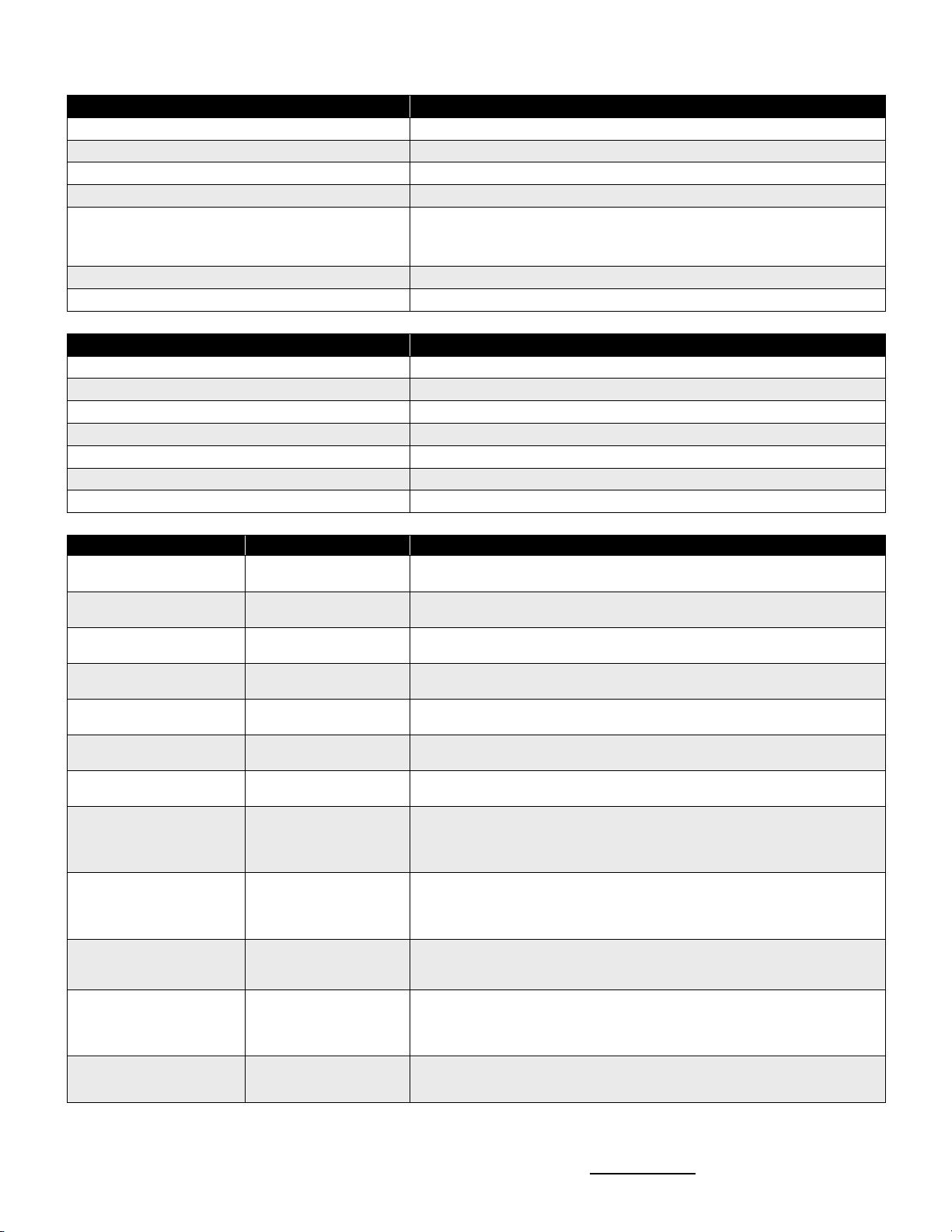
General Features
Default
Description
Turn On Volume 3
The radio can be set for a 0-10 volume level whenever the radio is turned on,
otherwise the radio will turn on at the minimum volume level.
Fixed Beep Volume 3
Set the volume of all radio alert beeps to a constant volume level of 0-10,
regardless of volume control setting.
Fixed Sidetone Volume 3
Set the sidetone volume to a constant volume level of 0-10, regardless of
volume control setting.
Call Tone Low level 1.5 seconds
A transmitted Call Tone level can be set for low or high, with a duration of 0.5
- 8 seconds.
Power On to Channel 1 Off
The radio will always turn on to Channel 1, otherwise the radio turns on to the
channel that was selected when you last turned the radio off.
Always On Off
The radio can be set to automatically turn-on any time power is applied to the
radio.
TX Timeout 60 seconds
A value between 1-255 seconds limits the time the radio can continuously
transmit.
DMR Callback Time 10 Seconds
When the base radio receives a valid call on a DMR channel, a 0-30 second
DMR Callback Time allows the radio to transmit a return call to the calling
Group or Individual. After the DMR Callback Time has expired the radio will
transmit on the DMR Channel’s Primary TX Contact.
P1 Button None
The P1 Button is programmed on a per-channel basis for DMR or Analog
Contacts, depending on the channel type. On a DMR channel this allows the
radio to initiate a call to any number of Group or Individual IDs from the DMR
Contacts list.
DMR Contacts Group 1001
All Call
The radio can be programmed with up to 48 Group or Individual ID Contacts
that can be used on any DMR channel. Each DMR Contact can be assigned
an 8-character name that will appear on the LCD display when in use.
Analog Contacts None
The radio can be programmed with up to 10 Analog Contacts that can be
used on any Analog channel. Each Analog Contact can be assigned an 8-
character name that will appear on the LCD display when in use. Analog
Contacts can be DTMF, Selcall or 2-Tone.
P2 Button
Scan
Send Call Tone
Analog Decode Reset
The P2 Button can be used to initiate a number of features that include Scan,
Monitor, Last Channel, Paging Reset, and more. Refer to the P2 Button
section of this manual for details.

RBS-477DMR DMR/ANALOG BASE RADIO USER MANUAL SPECIFICATIONS
Have questions? Call 800-872-1872 or visit our website at www.ritron.com 15
Channel Features
Default
Description
Channel Name Chan 1
Each channel can be programmed with a unique 8-character name that
appears on the top line of the LCD display when the channel is selected.
TX Beep Off
The radio will emit a beep when the transmitter is first activated to indicate
that is ready for broadcast.
Busy Channel TX Inhibit Off
The radio is unable to transmit on the channel when a signal is present on
the receiver.
RX Beep Off
The radio will emit a beep each time the radio stops receiving a signal,
indicating that the channel is clear to transmit.
Scan Resume Delay On
When operating on the Scan Channel, if this option is not set the radio will
resume scanning immediately after a received signal on this channel goes
away.
Monitor Lockout Off
The radio will not allow the user to monitor the channel, it will only receive
signals with the correct QC or DQC code.
Squelch 2
Squelch can be set between 0 and 7 to adjust the receiver carrier squelch
setting. A number 0 will set the squelch sensitivity to < .25 µV and allow
weak, distant signal to be received. A number 7 will set the squelch
sensitivity to > 1 µV and will block out all but strong, near range signals.
CTCSS/DCS
44 (None)
Analog Only -Select from 52 QC codes (CTCSS) or 103 DQC codes (DCS)
ANI on PTT None
Analog Only -A DTMF or Selcall encode string can be transmitted each time
the radio PTT button is pressed.
2-Tone, DTMF and Selcall
Decode None
Analog Only - The radio can be programmed for 2-Tone, DTMF and Selcall
Decode to screen incoming calls for the correct code.
Color Code 10
DMR Only –The Color Code can be set from 0 to 15. The Color Code can
be different for transmit and receive.
TX Contact 1001
DMR Only – A DMR channel is set to transmit on one of the 48 DMR
Contacts.
RX Group List
1001
All Call
DMR Only – A DMR channel is set to receive any number of Group contacts
from the 48 DMR Contacts.
Repeater Mode Off
DMR Only – When On the repeater time slot and Address can be
programmed.
Slot
Slot 1
DMR Only – Sets the TX slot for TDMA Direct Mode.
TDMA Direct Mode
TDMA Off
DMR Only – Sets the radio for TDMA Direct operation.
Analog Paging Decode
Default
Description
2-Tone, DTMF or Selcall
Decode None
The radio can be programmed for 2-Tone, DTMF and Selcall Decode to
screen incoming calls for the correct code.
All Call
Off
Can be set to decode an All Call code
Auto Reset Off
The radio will be set to Paging Decode mode after a period of inactivity
greater than the Decode Reset Time.
Group Call
Off
Can be set to decode a Group Call code.
Monitor Trip Off
The radio will automatically go into carrier squelch mode any time a 2-Tone,
DTMF or Selcall code is successfully decoded, and will remain there until the
Reset Timer has reset the decoder.
Squelch On Select On
The radio will be set to Paging Decode mode any time the channel is
selected.
Transpond Off
The radio will transmit a transpond tone after the 2-tone, DTMF or Selcall
code has been successfully decoded to let the user sending the code know
that it has been received.
Decode with Subtone Off
The radio cannot decode the 2-Tone, DTMF or Selcall code unless the
correct QC or DQC subtone is also decoded. If not checked 2-tone, DTMF or
Selcall is decoded regardless of subtone.
Ring Tone On
A ringing tone will be heard on the radio speaker any time the 2-tone, DTMF
or Selcall code has been successfully decoded.
Automatic Reset Time 10 seconds
Sets the length of time the radio can go with no activity before Auto Reset
places it into Paging Decode mode. If Monitor Trip is set, the radio will only
remain in Monitor mode for the Reset Time if the page is not answered.

RBS-477DMR DMR/ANALOG BASE RADIO USER MANUAL FCC AND IC LICENSE REQUIRED
Have questions? Call 800-872-1872 or visit our website at www.ritron.com 16
FCC LICENSING
The FCC requires the owners of radios operating on Part 90 frequencies to obtain a station license before using them.
The station licensee is responsible for ensuring that transmitter power, frequency and deviation are within the limits specified by the station license.
The station licensee is also responsible for proper operation and maintenance of the radio equipment. This includes checking the transmitter
frequency and deviation periodically, using appropriate methods.
To get an FCC license for VHF or UHF frequencies, submit FCC application Form 601. Your Ritron dealer can help you with this process.
HOW TO OBTAIN AN FCC RADIO LICENSE
Because your Ritron radio operates on Private Land Mobile frequencies, it is subject to the Rules and Regulations of the FCC, which requires all
operators of these frequencies to obtain a station license before operating their equipment. Make application for your FCC license on FCC Forms
601, Schedules D and H, and Fee Remittance Form 159.
To have forms and instructions faxed to you by the FCC, call the FCC Fax-On-Demand system at 202-418-0177 from your fax machine; request
Document numbers 3000159, 3060001, 3060003, and 3060006.
To have Document numbers 3000159, 3060001, 3060003, and 3060006 mailed to you, call the FCC Forms Hotline at 800-418-FORM (800-418-
3676).
For help with questions concerning the license application, contact the FCC at 888-CALL-FCC (888-225-5322) or log on at www.fcc.gov
You must decide which radio frequency(ies) you can operate on before filling out your application.
For help determining your frequencies, call Ritron at 800-USA-1-USA (800-872-1872).
INDUSTRY CANADA REGULATIONS
Industry Canada requires the owners of the radios to obtain a radio license before using them.
Application forms can be obtained from the nearest Industry Canada District office.
1. Fill in the items per the instructions. If you need additional space for any item, use the reverse side of the application.
2. Use a typewriter or print legibly.
3. Make a copy for your files.
4. Prepare a check or money order to “Receiver General for Canada”, for the amount listed at http://www.ic.gc.ca/eic/site/smt-
gst.nsf/eng/sf01027.html. (Licenses are renewed annually on April 1st. Refer to the calculation for application fees for each month.)
5. Mail the completed application, along with your check or money order, to the closest Industry Canada District Office.
Notes: Fees are subject to change without notice.
SAFETY STANDARDS
The FCC (with its action in General Docket 79-144, March 13, 1985) has adopted a safety standard for human exposure to radio frequency
electromagnetic energy emitted by FCC regulated equipment. Ritron observes these guidelines and recommends that you do also:
• DO NOT hold the radio so that the antenna is very close to or touching exposed parts of the body, especially the face or eyes, while
transmitting. Keep the radio vertical, eight inches away while talking into the front panel.
• DO NOT press the Push-To-Talk except when you intend to transmit.
• DO NOT operate radio equipment near electrical blasting caps or in an explosive atmosphere.
• DO NOT allow children to play with any radio equipment that contains a transmitting device.
• Repair of Ritron products should be performed only by Ritron authorized personnel.
SERVICE
Federal law prohibits you from making any internal adjustments to the transmitter, and / or from changing transmit frequencies unless you are
specifically designated by the licensee.
If your radio equipment fails to operate properly, or you wish to have the radio programmed, contact your local authorized dealer or Ritron.
U.S. Manufacturer:
RITRON, INC. - Repair Department
505 West Carmel Drive,
Carmel, Indiana 46032 USA
Phone: 317-846-1201
FAX: 317-846-4978
Email: customer_service@ritron.com

RBS-477DMR DMR/ANALOG BASE RADIO USER MANUAL RITRON WARRANTY INFORMATION
Have questions? Call 800-872-1872 or visit our website at www.ritron.com 17
RITRON, INC. LIMITED WARRANTY
WHAT THIS WARRANTY COVERS:
RITRON, INC. ("RITRON") provides the following warranty against defects in materials and/or workmanship in RITRON Radios and Accessories
under normal use and service during the applicable warranty period (as stated below). "Accessories" means antennas, holsters, chargers,
earphones, speaker/microphones and items contained in the programming and programming/service kits.
WHAT IS COVERED FOR HOW LONG WHAT RITRON WILL DO
Base Radio 1 year*During the first year after date of purchase, RITRON will repair or
replace the defective product, at RITRON's option, parts and labor
included at no charge.
Accessories 90 days**After date of purchase
WHAT THIS WARRANTY DOES NOT COVER:
• Any technical information provided with the covered product or any other RITRON products;
• Installation, maintenance or service of the product, unless this is covered by a separate written agreement with RITRON;
• Any products not furnished by RITRON which are attached or used with the covered product, or defects or damage from the use of the covered
product with equipment that is not covered (such as defects or damage from the charging or use of batteries other than with covered product);
• Defects or damage, including broken antennas, resulting from:
- misuse, abuse, improper maintenance, alteration, modification, neglect, accident or act of God,
- the use of covered products other than in normal and customary manner or,
- improper testing or installation;
• Defects or damages from unauthorized disassembly, repair or modification, or where unauthorized disassembly, repair or modification prevents
inspection and testing necessary to validate warranty claims;
• Defects or damages in which the serial number has been removed, altered or defaced.
• Batteries if any of the seals are not intact.
IMPORTANT: This warranty sets forth the full extent of RITRON’s express responsibilities regarding the covered products, and is given in lieu of all
other express warranties. What RITRON has agreed to do above is your sole and exclusive remedy. No person is authorized to make any other
warranty to you on behalf of RITRON. Warranties implied by state law, such as implied warranties of merchantability and fitness for a particular
purpose, are limited to the duration of this limited warranty as it applies to the covered product. Incidental and consequential damages are not
recoverable under this warranty (this includes loss of use or time, inconvenience, business interruption, commercial loss, lost profits or savings).
Some states do not allow the exclusion or limitation of incidental or consequential damages, or limitation on how long an implied warranty lasts, so
the above limitations or exclusions may not apply to you. Because each covered product system is unique, RITRON disclaims liability for range,
coverage, or operation of the system as a whole under this warranty.
WHO IS COVERED BY THIS WARRANTY: This warranty is given only to the purchaser or lessee of covered products when acquired for
use, not resale. This warranty is not assignable or transferable.
HOW TO GET WARRANTY SERVICE: To receive warranty service, you must deliver or send the defective product, delivery costs and
insurance prepaid, within the applicable warranty period, to RITRON, INC., 505 West Carmel Drive, Carmel, Indiana 46032, Attention: Warranty
Department. Please point out the nature of the defect in as much detail as you can. You must retain your sales or lease receipt (or other written
evidence of the date of purchase) and deliver it along with the product. If RITRON chooses to repair or replace a defective product, RITRON may
replace the product or any part or component with reconditioned product, parts or components. Replacements are covered for the balance of the
original applicable warranty period. All replaced covered products, parts or components become RITRON’s property.
RIGHTS TO SOFTWARE RETAINED : Title and all rights or licenses to patents, copyrights, trademarks and trade secrets in any RITRON
software contained in covered products are and shall remain in RITRON. RITRON nevertheless grants you a limited non-exclusive, transferable right
to use the RITRON software only in conjunction with covered products. No other license or right to the RITRON software is granted or permitted.
YOUR RIGHTS UNDER STATE LAW: This warranty gives you specific legal rights, and you may also have other rights which vary from state
to state.
WHERE THIS WARRANTY IS VALID: This warranty is valid only within the United States, the District of Columbia and Puerto Rico.
Table of contents
Other Ritron Radio manuals

Ritron
Ritron RPM-150 User manual

Ritron
Ritron RPM 60 Series User manual

Ritron
Ritron QUICK TQLK Instructions for use

Ritron
Ritron SLX Series User manual

Ritron
Ritron DATAFLOW RTU User manual

Ritron
Ritron RF320 Series User manual

Ritron
Ritron MOBILE RADIO User manual

Ritron
Ritron RPM 60 Series User manual

Ritron
Ritron Jobcom JBC-100 User manual

Ritron
Ritron RPM 60 Series User manual


