Ericsson GE EDACS FMD User manual

EMERGENCY NUMBERS
_________________________________________________________
Police
_________________________________________________________
State Police
_________________________________________________________
Fire
_________________________________________________________
Poison Control
_________________________________________________________
Ambulance
Life Saving and Rescue Squad
_________________________________________________________
Printed in U.S.A.
Mobile Communications
EDACSFMD
SELECT MODEL
Operator’s Manual
LBI-38102A

Copyright© May 1988, General Electric Company
TABLE OF CONTENTS
Section/Paragraph Page
INTRODUCTION . . . . . . . . . . . . . . . . . . . . . . . . 3
CONTROLS AND DISPLAYS . . . . . . . . . . . . . . . . . 3
DISPLAYS . . . . . . . . . . . . . . . . . . . . . . . . . . 4
CONTROLS . . . . . . . . . . . . . . . . . . . . . . . . . . 5
EMERGENCY FEATURE . . . . . . . . . . . . . . . . . . 5
OPERATION . . . . . . . . . . . . . . . . . . . . . . . . . . . 6
GROUP SELECTION . . . . . . . . . . . . . . . . . . . . 6
SYSTEM SELECTION . . . . . . . . . . . . . . . . . . . . 6
GETTING STARTED . . . . . . . . . . . . . . . . . . . . 6
SETTING BACKLIGHT LEVEL . . . . . . . . . . . . . . 7
SENDING AND RECEIVING TRUNKED MESSAGES . . 7
Receiving A Message . . . . . . . . . . . . . . . . . . . 7
Sending A Message . . . . . . . . . . . . . . . . . . . . 7
SENDING AND RECEIVING
CONVENTIONAL MESSAGES . . . . . . . . . . . . . . . 8
Receiving A Message . . . . . . . . . . . . . . . . . . . 8
Sending A Message . . . . . . . . . . . . . . . . . . . . 8
SPECIAL FEATURES . . . . . . . . . . . . . . . . . . . . . . 9
ALERT TONES . . . . . . . . . . . . . . . . . . . . . . . . 9
RECEIVING AN EMERGENCY CALL . . . . . . . . . . 10
SENDING AN EMERGENCY CALL . . . . . . . . . . . . 10
CLEARING AN EMERGENCY CALL . . . . . . . . . . . 10
SPECIAL CALL . . . . . . . . . . . . . . . . . . . . . . . 10
Receiving An Individual Call (Trunked Mode) . . . . . . 10
Sending A Special Call . . . . . . . . . . . . . . . . . . 11
Telephone Interconnect . . . . . . . . . . . . . . . . . . 11
IN CASE OF DIFFICULTY . . . . . . . . . . . . . . . . . . . 12
OPERATING TIPS . . . . . . . . . . . . . . . . . . . . . . . . 12
2
WARRANTY
A. Ericsson GE Mobile Communications Inc. (hereinafter "Seller") warrants to the original
purchaser for use (hereinafter "Buyer") that Equipment manufactured by Seller shall be
free from defects in material, workmanship and title, and shall conform to its published
specifications. With respect to any Equipment not manufactured by Seller (except for in-
tegral parts of Seller’s Equipment to which the warranties set forth above shall apply).
Seller gives no warranty, and only the warranty, if any, given by the manufacturer shall
apply. Batteries are excluded from this warranty but are warranted under a separate
Nickel-Cadmium Battery Warranty.
B. Seller’s obligations set forth in Paragraph C below shall apply only tofailures to meet
the above warranties (except as to title) occurring within the following periods of time
from date of sale to the Buyer and are conditioned on Buyer’s giving written notice to
Seller within thirty (30) days of such occurrence:
1. for fuses, incandescent lamps, vacuum tubes and non-rechargeable batteries, op-
erable on arrival only.
2. for parts and accessories (except as noted in B.1) sold by Seller’s Service Parts
Operation, ninety (90) days.
3. for all other Equipment of Seller’s manufacture, one (1)year.
C. If any Equipment fails to meet the foregoing warranties, Seller shall correct the failure at
its option (i) by repairing any defective or damaged part or parts thereof, or (ii) by mak-
ing available at Seller’s factory any necessary repaired or replacement parts. Any re-
paired or replacement part furnished hereunder shall be warranted for the remainder of
the warranty period of the Equipment in which it is installed. Where such failure cannot
be corrected by Seller’s reasonable efforts, the parties will negotiate an equitable adjust-
ment in price. Labor to perform warranty service will be provided at no change only for
the Equipment covered under Paragraph B.3, and only during the first three (3) months
following the date of sale to the Buyer. Thereafter, labor will be charged at prevailing
rates. To be eligible for no-charge labor, service must be performed by an authorized
General Electric Service Station or other Servicer approved for these purposes either at
its place of business during normal business hours, for mobile or personal equipment,
or at the Buyer’s location, for fixed location equipment. Service on fixed location equip-
ment more than thirty (30) miles from the Service Station or other approved Servicer’s
place of business will include a charge for transportation. Equipment located off-shore is
not eligible for no-charge labor.
D. Seller’s obligations under Paragraph C shall not apply to any Equipment, or part thereof,
which (i) has been modified or otherwise altered other than pursuant to Seller’s written
instructions or written approval or, (ii) is normally consumed in operation or, (iii) has a
normal life inherently shorter than the warranty periods specified in Paragraph B, or (iv)
is not properly stored, installed, used, maintained or repaired, or, (v) has been subjected
to any other kind of misuse or detrimental exposure, or has been involved in an acci-
dent.
E. The preceding paragraphs set forth the exclusive remedies for claims (except as to title)
based upon defects in or nonconformity of the Equipment, whether the claim is in con-
tract, warranty, tort (including negligence), strict liability or otherwise, and however insti-
tuted. Upon the expiration of the warranty period, all such liability shall terminate. The
foregoing warranties are exclusive and in lieu of all other warranties, whether oral, writ-
ten, expressed, implied or statutory. NO IMPLIED OR STATUTORY WARRANTIES OF
MERCHANTABILITY OR FITNESS FOR PARTICULAR PURPOSE SHALL APPLY. IN
NO EVENT SHALL THE SELLER BE LIABLE FOR ANY INCIDENTAL, CONSEQUEN-
TIAL, SPECIAL, INDIRECT OR EXEMPLARY DAMAGES.
This warranty applies only within the United States.
1-800-528-7711 (1-800-237-0138 in Virginia).
ECX-362R
15
SAFETY INFORMATION
The operator of any mobile radio should be aware of certain hazards
common to the operation of vehicular radio transmissions.
A list of the possible hazards are:
•Explosive Atmospheres
Just as it is dangerous to fuel a vehicle with the motor running, be
sure to turn the radio off while fueling the vehicle. Do Not carry
containers of fuel in the trunk of the vehicle when the radio is
mounted in the trunk.
•Interference To Vehicular Electronic Systems
Electronic fuel injection systems, electronic anti-skid breaking
systems, electronic cruise control systems, etc., are typical of the
types of electronic devices that may malfunction due to the lack
of protection from radio frequency energy present when transmit-
ting. If the vehicle contains such equipment, consult the dealer for
the make of vehicle and enlist his aid in determining if such elec-
tronic circuits perform normally when the radio is transmitting.
•Dynamite Blasting Caps
Dynamite blasting caps may be caused to explode by operating a
radio within 500 feet of the blasting caps. Always obey the "Turn
Off Two Way Radio" signs posted where dynamite is being used.
When transporting blasting caps in your vehicle:
a. Carry the blasting caps in a closed metal box with a soft lin-
ing.
b. Leave the radio OFF whenever the blasting caps are being
put into or removed from the vehicle.
•Radio Frequency Energy
To prevent burns or related physical injury from radio frequency
energy, do not operate the transmitter when anyone outside of the
vehicle is within two feet of the antenna.
14
INTRODUCTION
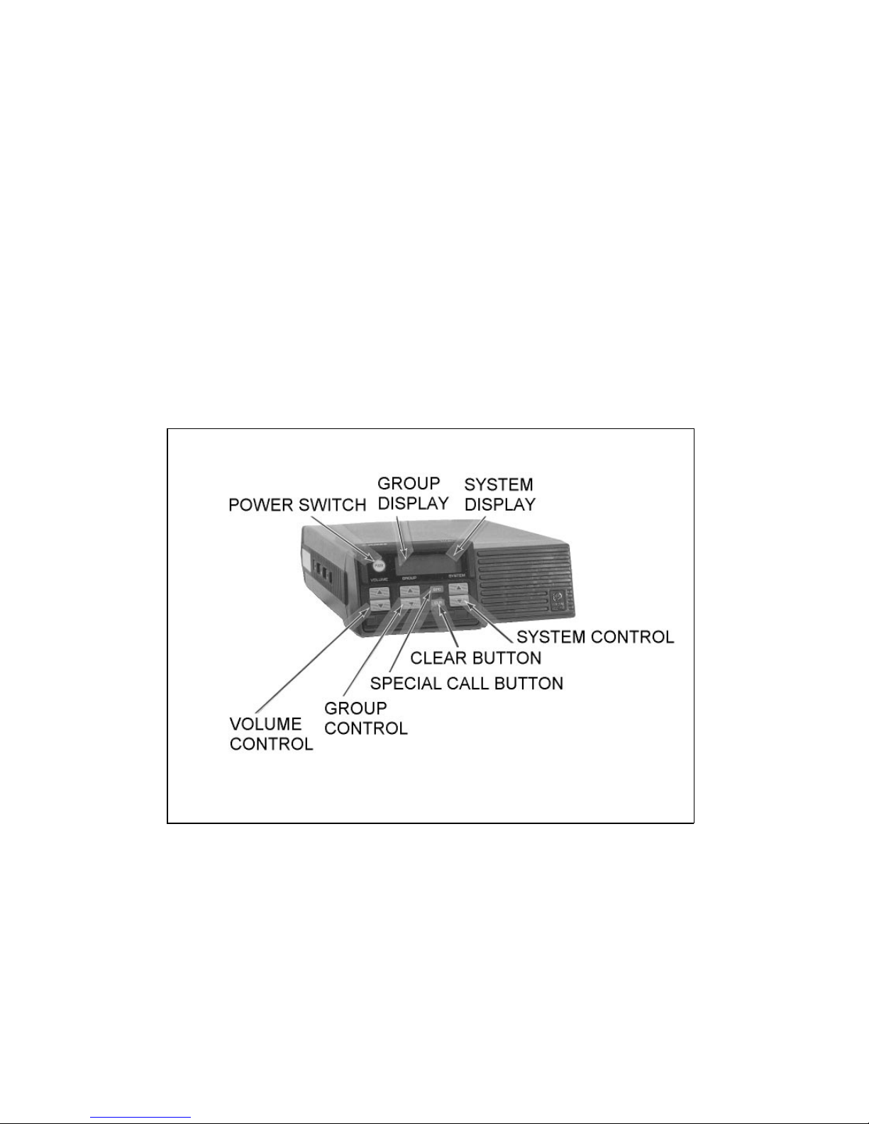
The EDACS FMD is a synthesized mobile radio designed for high
reliability and ease of operation. Its small size makes the radio ideal for
front mounting. All operating controls and indicators are located on the
front panel (Figure 1). A few features of the radio are listed below:
•Clear display, even in bright sunlight
•Accommodates both voice and data transmission
•Button and display backlighting for nighttime operation
•Adaptable for remote mounting
•External switch sends instant emergency signal
•Multiple Systems, Groups, and Channels
•Special call for radio-to-radio or telephone interconnect
calls
CONTROLS AND DISPLAYS
Controls and displays on the EDACS FMD Select model are de-
scribed in this section.
FIGURE 1 - EDACS FMD SELECT CONTROL PANEL
3
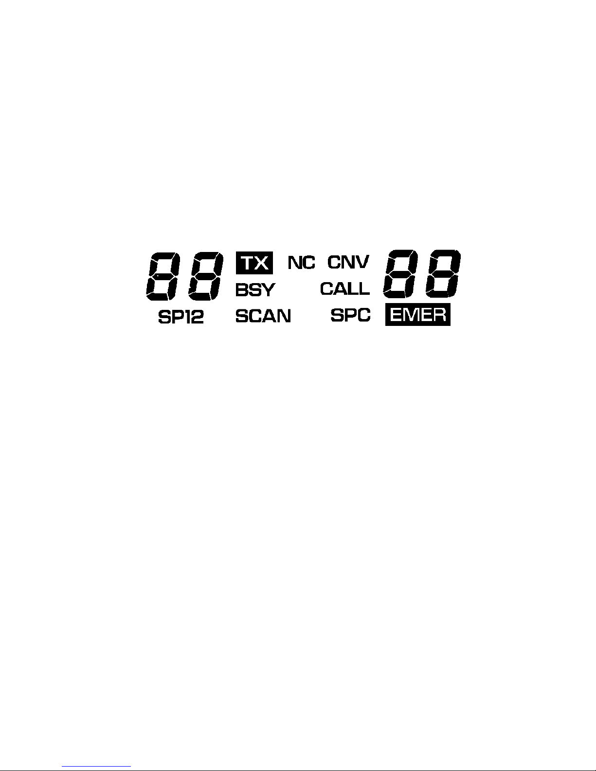
DISPLAYS
The display shows current operating information including Group,
System, or Channel. It also shows when the radio is in emergency op-
eration and shows different status flags. An example of the display is
shown below with all the status flags displayed. When you are using the
radio, only the active performance indicators and characters will show.
When the radio is turned on, the display will show the system and group
selection.
TX Transmit status flag. This status flag is on when the radio is
transmitting.
BSY Channel busy status flag. This status flag is on when the radio
receives a call or when a conventional channel is in use.
NC No control channel status flag. This status flag is on when the
control channel is not available (out of range or not operating).
On supervisory units, the flag flashes when site equipment is
in failsoft.
CNV Conventional system status flag. This status flag is on when
operating on a conventional system.
EMER Emergency status flag. Displayed when the external emer-
gency switch (optional) is activated and when an emergency
call is received.
CALL Flashes when programmed calls are received.
SPC Special call status flag. Displayed when an individual call is
received or a special call is selected.
4
OPERATING TIPS
•Remember to wait for the beep before speaking when transmit-
ting.
The following conditions tend to reduce the effective range of two-
way radios and should be avoided whenever possible.
•Operating the radio in low areas of the terrain, or while under
power lines or bridges.
•Obstructions such as mountains or buildings between the re-
peater site and the individual receiving the message.
Moving in another direction (towards the strongest signal), or mov-
ing to a higher elevation, may also improve communication.
13

when dialing telephone numbers. If the number is pre-stored, skip
this Step. Release the PTT button.
5. When the call is answered, press the PTT button and wait for the
tone before speaking.
6. Release the PTT button and listen for any reply.
7. When your call is finished, press the CLR button. The previously
selected group and system will appear on the display.
IN CASE OF DIFFICULTY
The following suggestions should be tried before returning your ra-
dio for service.
PROBLEM SOLUTION
First part of message not
sent. Channel not assigned before transmitting
(trunked system). Wait for beep tone before
beginning message.
Messages not received. 1. Volume level set too low. Increase setting
of VOLUME control.
2. Out of range of repeater or station.
Messages not transmitted. 1. Radio not turned on.
2. PTT not fully pressed. Make sure TX
status flag is on before transmitting.
3. Out of range of repeater or station.
Transmitted messages are
garbled. 1. Too close or too far from microphone.
Try different distance from microphone,
and/or different speaking level.
2. Out of range of repeater or station.
You cannot talk and listen at the same time as with a regular
telephone. Whenever you talk you will not hear the other party.
NOTE
12
SYSTEM Shows the selected system number.
GROUP Shows the selected group number.
The display has a backlight so you can read the display at night or in
dimly lit areas.
CONTROLS
PWR
(Power) A red pushbutton is used to turn the radio on and off.
VOLUME These buttons set the receive volume level. Press the ▲
button to increase the volume or press the ▼button to
lower the volume. Hold the button down until the desired
audio tone is heard (a tone will not be heard if the BSY
status flag is on). The radio stores the selected volume level
even when power is off.
GROUP The GROUP buttons change the group selection. Pressing
▲or ▼will change the group selection. The ▲button se-
lects the next group, and ▼button selects the previous
group.
SYSTEM These buttons change the system selection. Pressing ▲or
▼will change the system selection. The ▲button selects
the next system, and ▼button selects the previous system.
SPC Pressing this button causes the radio to enter the special
Call mode. Special Call allows you to place calls to indi-
vidual radios or telephone numbers. Use the GROUP ▲
and ▼buttons to select Special Calls in Special Call mode.
CLR Used to clear an emergency (supervisory units only), clear
Special Calls, and when setting the backlight level.
EMERGENCY FEATURE
Your radio is equipped with an emergency communications feature
that may be activated through an optional externally mounted switch.
When you activate the external emergency switch (optional), you will
be given the highest priority for voice communication. An emergency
5

message with your radio ID will be sent to the dispatcher and your radio
display will show the EMER status flag. Everyone in your group will
see an emergency indication on their radios.
OPERATION
GROUP SELECTION
The GROUP buttons change your Group (or conventional channel)
selection. Press the ▲button to view the next Group choice or ▼to
view the previous Group choice. Release the button when the display
shows the Group you want. If the displayed Group does not change, you
have reached the limit and will have to press the opposite direction to
see other selections. These buttons will automatically ramp when held
down.
SYSTEM SELECTION
Select a trunked or conventional System by pressing the SYSTEM
buttons. Press the ▲button to see the next System choice or press the
▼button to see the previous System choice. Release the button when
the display shows the System you want. If the System message does not
change, you have reached the limit and will have to press the button in
the opposite direction to see other selections. These buttons will auto-
matically ramp when held down.
GETTING STARTED
1. Press the red PWR button to turn the radio on. The display will
become visible.
2. Adjust the volume using the VOLUME buttons.
Your radio is now set up for basic operation. The BSY status flag
will be on when a call is received.
The group may change when the system selection is changed. This
happens when the selected system does not contain the previously
selected group. Make sure the GROUP selection is correct after
selecting a SYSTEM.
NOTE
6
Sending A Special Call
You may make Special Calls with your radio through the Special
Call feature.
1. Press and release the SPC button. The SPC status flag will come
on and the system display will change to SP. The group display
will change to the previously selected special call number.
2. Press the GROUP buttons to search (forward or reverse direction)
through the displayed list of Special Call numbers. When the de-
sired Special Call number appears on the display, release the
GROUP button.
3. Press the PTT button on the microphone and make your call.
4. Release the PTT button when you are done talking, and listen for
any reply.
5. When the call is finished, press the CLR button or hang up the
microphone. The display will change to the previously selected
group and system.
Telephone Interconnect
You may make telephone calls using the Special Call feature and an
optional DTMF microphone. Make a telephone interconnect call as fol-
lows:
1. Press the SPC button, the SPC status flag will come on. The sys-
tem display will change to the letters SP. The group display will
change to one of the previously selected special call numbers.
2. Press the GROUP buttons until the special call number for tele-
phone interconnect appears in the group display.
3. Press the PTT button on the microphone and wait for a dial tone
(or ringing if the number is pre-stored).
4. Enter the telephone number followed by * (star) using the keypad
on the microphone. Allow enough time for the transmitter to key
11

RECEIVING AN EMERGENCY CALL
When you receive an emergency call a short beep will sound, the
EMER status flag will flash, and the BSY status flag will come on. Fol-
low your standard emergency procedures.
SENDING AN EMERGENCY CALL
To send an Emergency call proceed as follows:
1. Activate the external emergency switch (optional). The EMER
and TX status flags will come on (unless programmed off).
2. Press the PTT button on the microphone, and speak into the mi-
crophone in a normal voice.
3. Release the PTT button when the transmission is completed, and
listen for any reply. The TX status flag will go out.
CLEARING AN EMERGENCY CALL
If your radio has been programmed as a supervisory unit, you may
clear emergency calls. When the emergency is no longer in effect, the
emergency call may be cleared as follows:
1. Press and hold the CLR button while pressing the external emer-
gency switch (optional).
2. Wait for the EMER status flag to go off.
3. Release both buttons.
SPECIAL CALL
Receiving An Individual Call (Trunked Mode)
When you receive an individual call (call directed only to your ra-
dio), the CALL and BSY status flags will be displayed. If you want to
respond to the call, you have up to five seconds to press the PTT button.
Your call will automatically be directed to the station calling you.
10
SETTING BACKLIGHT LEVEL
The level of backlighting for the LCD may be adjusted as follows:
1. Press and hold the CLR button.
2. Press the GROUP ▲or ▼button until the desired level of back-
lighting (off, low, medium, or high) is obtained. The backlight
level is stored when the radio is turned off.
3. Release the CLR button.
SENDING AND RECEIVING TRUNKED MESSAGES
When operating in a trunked system (normal operation), use the pro-
cedures in this section. Operation in the conventional channel mode is
described under SENDING AND RECEIVING CONVENTIONAL
MESSAGES.
Receiving A Message
1. Press the VOLUME button and listen for the desired level of
audio tone.
2. Select the trunked system by operating the SYSTEM buttons.
3. Select the desired group by operating the GROUP buttons.
The radio will now receive calls directed to the selected system and
group. If an individual call (call directed only to your radio) is received,
the SPC and BSY status flags will be displayed.
Sending A Message
1. Select the desired system by operating the SYSTEM buttons.
Pressing the CLR button disables the squelch on conventional
channels. You may want to reduce the volume before setting the
backlight level to prevent excessive noise in the speaker.
NOTE
7

2. Select the desired group by operating the GROUP buttons.
3. When the BSY status flag is off, press the PTT button on the mi-
crophone. Wait until the TX and BSY status flags are displayed
and a tone is heard.
4. Hold the microphone about six inches from your mouth and
speak normally.
5. Release the PTT button when the transmission is complete, and
listen for any reply. The TX and BSY status flags will go off.
SENDING AND RECEIVING CONVENTIONAL MESSAGES
The procedures described here are for operating in a conventional
channel mode. Use these procedures if you have a conventional system,
or in the event of a failure of the trunked system.
Receiving A Message
1. Press the VOLUME button and listen for the desired level of
audio tone.
2. Select a conventional channel system by operating the SYSTEM
buttons.
3. Select the desired channel by operating the GROUP buttons. The
radio will now receive messages over the channel.
Sending A Message
1. Select a conventional channel system by operating the SYSTEM
buttons.
2. Select the desired channel by operating the GROUP buttons.
3. Insure that there is no other transmission on the channel (BSY
status flag off).
4. Press the PTT button on the microphone and wait until the TX
status flag is displayed and a tone is heard.
8
5. Hold the microphone about six inches from your mouth and
speak normally.
6. Release the PTT button when the transmission is complete, and
listen for any reply. The TX status flag will go off.
SPECIAL FEATURES
ALERT TONES
Your radio produces audio tones when the buttons are pressed and at
other times during normal operation.
•Short tone when a button is pressed.
•Short tone when emergency operation is used.
•Short tone after PTT is pressed and radio is ready to transmit.
•Call-queued tone. A high pitched beep signalling the call has
been queued and will be placed as soon as a channel is assigned.
Wait until call is placed. The radio flashes the BSY status flag
and disables PTT when a call is queued.
•System busy. Three low pitched beeps indicating the system is
busy. Try your call later.
•Auto-key tone. A long tone if the PTT is not pressed when the
site equipment assigns a channel. You have up to two seconds to
press the PTT after the tone to keep the assigned channel.
•Carrier Control Timer (CCT) Tone. A warning signal which
sounds after the radio has been continuously transmitting for a
pre-programmed time. The signal turns off when PTT is re-
leased. A five-beep signal followed by a low tone is used on
trunked systems. On conventional systems, the low tone beep
sounds until PTT is released.
9

RECEIVING AN EMERGENCY CALL
When you receive an emergency call a short beep will sound, the
EMER status flag will flash, and the BSY status flag will come on. Fol-
low your standard emergency procedures.
SENDING AN EMERGENCY CALL
To send an Emergency call proceed as follows:
1. Activate the external emergency switch (optional). The EMER
and TX status flags will come on (unless programmed off).
2. Press the PTT button on the microphone, and speak into the mi-
crophone in a normal voice.
3. Release the PTT button when the transmission is completed, and
listen for any reply. The TX status flag will go out.
CLEARING AN EMERGENCY CALL
If your radio has been programmed as a supervisory unit, you may
clear emergency calls. When the emergency is no longer in effect, the
emergency call may be cleared as follows:
1. Press and hold the CLR button while pressing the external emer-
gency switch (optional).
2. Wait for the EMER status flag to go off.
3. Release both buttons.
SPECIAL CALL
Receiving An Individual Call (Trunked Mode)
When you receive an individual call (call directed only to your ra-
dio), the CALL and BSY status flags will be displayed. If you want to
respond to the call, you have up to five seconds to press the PTT button.
Your call will automatically be directed to the station calling you.
10
SETTING BACKLIGHT LEVEL
The level of backlighting for the LCD may be adjusted as follows:
1. Press and hold the CLR button.
2. Press the GROUP ▲or ▼button until the desired level of back-
lighting (off, low, medium, or high) is obtained. The backlight
level is stored when the radio is turned off.
3. Release the CLR button.
SENDING AND RECEIVING TRUNKED MESSAGES
When operating in a trunked system (normal operation), use the pro-
cedures in this section. Operation in the conventional channel mode is
described under SENDING AND RECEIVING CONVENTIONAL
MESSAGES.
Receiving A Message
1. Press the VOLUME button and listen for the desired level of
audio tone.
2. Select the trunked system by operating the SYSTEM buttons.
3. Select the desired group by operating the GROUP buttons.
The radio will now receive calls directed to the selected system and
group. If an individual call (call directed only to your radio) is received,
the SPC and BSY status flags will be displayed.
Sending A Message
1. Select the desired system by operating the SYSTEM buttons.
Pressing the CLR button disables the squelch on conventional
channels. You may want to reduce the volume before setting the
backlight level to prevent excessive noise in the speaker.
NOTE
7

message with your radio ID will be sent to the dispatcher and your radio
display will show the EMER status flag. Everyone in your group will
see an emergency indication on their radios.
OPERATION
GROUP SELECTION
The GROUP buttons change your Group (or conventional channel)
selection. Press the ▲button to view the next Group choice or ▼to
view the previous Group choice. Release the button when the display
shows the Group you want. If the displayed Group does not change, you
have reached the limit and will have to press the opposite direction to
see other selections. These buttons will automatically ramp when held
down.
SYSTEM SELECTION
Select a trunked or conventional System by pressing the SYSTEM
buttons. Press the ▲button to see the next System choice or press the
▼button to see the previous System choice. Release the button when
the display shows the System you want. If the System message does not
change, you have reached the limit and will have to press the button in
the opposite direction to see other selections. These buttons will auto-
matically ramp when held down.
GETTING STARTED
1. Press the red PWR button to turn the radio on. The display will
become visible.
2. Adjust the volume using the VOLUME buttons.
Your radio is now set up for basic operation. The BSY status flag
will be on when a call is received.
The group may change when the system selection is changed. This
happens when the selected system does not contain the previously
selected group. Make sure the GROUP selection is correct after
selecting a SYSTEM.
NOTE
6
Sending A Special Call
You may make Special Calls with your radio through the Special
Call feature.
1. Press and release the SPC button. The SPC status flag will come
on and the system display will change to SP. The group display
will change to the previously selected special call number.
2. Press the GROUP buttons to search (forward or reverse direction)
through the displayed list of Special Call numbers. When the de-
sired Special Call number appears on the display, release the
GROUP button.
3. Press the PTT button on the microphone and make your call.
4. Release the PTT button when you are done talking, and listen for
any reply.
5. When the call is finished, press the CLR button or hang up the
microphone. The display will change to the previously selected
group and system.
Telephone Interconnect
You may make telephone calls using the Special Call feature and an
optional DTMF microphone. Make a telephone interconnect call as fol-
lows:
1. Press the SPC button, the SPC status flag will come on. The sys-
tem display will change to the letters SP. The group display will
change to one of the previously selected special call numbers.
2. Press the GROUP buttons until the special call number for tele-
phone interconnect appears in the group display.
3. Press the PTT button on the microphone and wait for a dial tone
(or ringing if the number is pre-stored).
4. Enter the telephone number followed by * (star) using the keypad
on the microphone. Allow enough time for the transmitter to key
11

when dialing telephone numbers. If the number is pre-stored, skip
this Step. Release the PTT button.
5. When the call is answered, press the PTT button and wait for the
tone before speaking.
6. Release the PTT button and listen for any reply.
7. When your call is finished, press the CLR button. The previously
selected group and system will appear on the display.
IN CASE OF DIFFICULTY
The following suggestions should be tried before returning your ra-
dio for service.
PROBLEM SOLUTION
First part of message not
sent. Channel not assigned before transmitting
(trunked system). Wait for beep tone before
beginning message.
Messages not received. 1. Volume level set too low. Increase setting
of VOLUME control.
2. Out of range of repeater or station.
Messages not transmitted. 1. Radio not turned on.
2. PTT not fully pressed. Make sure TX
status flag is on before transmitting.
3. Out of range of repeater or station.
Transmitted messages are
garbled. 1. Too close or too far from microphone.
Try different distance from microphone,
and/or different speaking level.
2. Out of range of repeater or station.
You cannot talk and listen at the same time as with a regular
telephone. Whenever you talk you will not hear the other party.
NOTE
12
SYSTEM Shows the selected system number.
GROUP Shows the selected group number.
The display has a backlight so you can read the display at night or in
dimly lit areas.
CONTROLS
PWR
(Power) A red pushbutton is used to turn the radio on and off.
VOLUME These buttons set the receive volume level. Press the ▲
button to increase the volume or press the ▼button to
lower the volume. Hold the button down until the desired
audio tone is heard (a tone will not be heard if the BSY
status flag is on). The radio stores the selected volume level
even when power is off.
GROUP The GROUP buttons change the group selection. Pressing
▲or ▼will change the group selection. The ▲button se-
lects the next group, and ▼button selects the previous
group.
SYSTEM These buttons change the system selection. Pressing ▲or
▼will change the system selection. The ▲button selects
the next system, and ▼button selects the previous system.
SPC Pressing this button causes the radio to enter the special
Call mode. Special Call allows you to place calls to indi-
vidual radios or telephone numbers. Use the GROUP ▲
and ▼buttons to select Special Calls in Special Call mode.
CLR Used to clear an emergency (supervisory units only), clear
Special Calls, and when setting the backlight level.
EMERGENCY FEATURE
Your radio is equipped with an emergency communications feature
that may be activated through an optional externally mounted switch.
When you activate the external emergency switch (optional), you will
be given the highest priority for voice communication. An emergency
5

DISPLAYS
The display shows current operating information including Group,
System, or Channel. It also shows when the radio is in emergency op-
eration and shows different status flags. An example of the display is
shown below with all the status flags displayed. When you are using the
radio, only the active performance indicators and characters will show.
When the radio is turned on, the display will show the system and group
selection.
TX Transmit status flag. This status flag is on when the radio is
transmitting.
BSY Channel busy status flag. This status flag is on when the radio
receives a call or when a conventional channel is in use.
NC No control channel status flag. This status flag is on when the
control channel is not available (out of range or not operating).
On supervisory units, the flag flashes when site equipment is
in failsoft.
CNV Conventional system status flag. This status flag is on when
operating on a conventional system.
EMER Emergency status flag. Displayed when the external emer-
gency switch (optional) is activated and when an emergency
call is received.
CALL Flashes when programmed calls are received.
SPC Special call status flag. Displayed when an individual call is
received or a special call is selected.
4
OPERATING TIPS
•Remember to wait for the beep before speaking when transmit-
ting.
The following conditions tend to reduce the effective range of two-
way radios and should be avoided whenever possible.
•Operating the radio in low areas of the terrain, or while under
power lines or bridges.
•Obstructions such as mountains or buildings between the re-
peater site and the individual receiving the message.
Moving in another direction (towards the strongest signal), or mov-
ing to a higher elevation, may also improve communication.
13

SAFETY INFORMATION
The operator of any mobile radio should be aware of certain hazards
common to the operation of vehicular radio transmissions.
A list of the possible hazards are:
•Explosive Atmospheres
Just as it is dangerous to fuel a vehicle with the motor running, be
sure to turn the radio off while fueling the vehicle. Do Not carry
containers of fuel in the trunk of the vehicle when the radio is
mounted in the trunk.
•Interference To Vehicular Electronic Systems
Electronic fuel injection systems, electronic anti-skid breaking
systems, electronic cruise control systems, etc., are typical of the
types of electronic devices that may malfunction due to the lack
of protection from radio frequency energy present when transmit-
ting. If the vehicle contains such equipment, consult the dealer for
the make of vehicle and enlist his aid in determining if such elec-
tronic circuits perform normally when the radio is transmitting.
•Dynamite Blasting Caps
Dynamite blasting caps may be caused to explode by operating a
radio within 500 feet of the blasting caps. Always obey the "Turn
Off Two Way Radio" signs posted where dynamite is being used.
When transporting blasting caps in your vehicle:
a. Carry the blasting caps in a closed metal box with a soft lin-
ing.
b. Leave the radio OFF whenever the blasting caps are being
put into or removed from the vehicle.
•Radio Frequency Energy
To prevent burns or related physical injury from radio frequency
energy, do not operate the transmitter when anyone outside of the
vehicle is within two feet of the antenna.
14
INTRODUCTION
The EDACS FMD is a synthesized mobile radio designed for high
reliability and ease of operation. Its small size makes the radio ideal for
front mounting. All operating controls and indicators are located on the
front panel (Figure 1). A few features of the radio are listed below:
•Clear display, even in bright sunlight
•Accommodates both voice and data transmission
•Button and display backlighting for nighttime operation
•Adaptable for remote mounting
•External switch sends instant emergency signal
•Multiple Systems, Groups, and Channels
•Special call for radio-to-radio or telephone interconnect
calls
CONTROLS AND DISPLAYS
Controls and displays on the EDACS FMD Select model are de-
scribed in this section.
FIGURE 1 - EDACS FMD SELECT CONTROL PANEL
3

Copyright© May 1988, General Electric Company
TABLE OF CONTENTS
Section/Paragraph Page
INTRODUCTION . . . . . . . . . . . . . . . . . . . . . . . . 3
CONTROLS AND DISPLAYS . . . . . . . . . . . . . . . . . 3
DISPLAYS . . . . . . . . . . . . . . . . . . . . . . . . . . 4
CONTROLS . . . . . . . . . . . . . . . . . . . . . . . . . . 5
EMERGENCY FEATURE . . . . . . . . . . . . . . . . . . 5
OPERATION . . . . . . . . . . . . . . . . . . . . . . . . . . . 6
GROUP SELECTION . . . . . . . . . . . . . . . . . . . . 6
SYSTEM SELECTION . . . . . . . . . . . . . . . . . . . . 6
GETTING STARTED . . . . . . . . . . . . . . . . . . . . 6
SETTING BACKLIGHT LEVEL . . . . . . . . . . . . . . 7
SENDING AND RECEIVING TRUNKED MESSAGES . . 7
Receiving A Message . . . . . . . . . . . . . . . . . . . 7
Sending A Message . . . . . . . . . . . . . . . . . . . . 7
SENDING AND RECEIVING
CONVENTIONAL MESSAGES . . . . . . . . . . . . . . . 8
Receiving A Message . . . . . . . . . . . . . . . . . . . 8
Sending A Message . . . . . . . . . . . . . . . . . . . . 8
SPECIAL FEATURES . . . . . . . . . . . . . . . . . . . . . . 9
ALERT TONES . . . . . . . . . . . . . . . . . . . . . . . . 9
RECEIVING AN EMERGENCY CALL . . . . . . . . . . 10
SENDING AN EMERGENCY CALL . . . . . . . . . . . . 10
CLEARING AN EMERGENCY CALL . . . . . . . . . . . 10
SPECIAL CALL . . . . . . . . . . . . . . . . . . . . . . . 10
Receiving An Individual Call (Trunked Mode) . . . . . . 10
Sending A Special Call . . . . . . . . . . . . . . . . . . 11
Telephone Interconnect . . . . . . . . . . . . . . . . . . 11
IN CASE OF DIFFICULTY . . . . . . . . . . . . . . . . . . . 12
OPERATING TIPS . . . . . . . . . . . . . . . . . . . . . . . . 12
2
WARRANTY
A. Ericsson GE Mobile Communications Inc. (hereinafter "Seller") warrants to the original
purchaser for use (hereinafter "Buyer") that Equipment manufactured by Seller shall be
free from defects in material, workmanship and title, and shall conform to its published
specifications. With respect to any Equipment not manufactured by Seller (except for in-
tegral parts of Seller’s Equipment to which the warranties set forth above shall apply).
Seller gives no warranty, and only the warranty, if any, given by the manufacturer shall
apply. Batteries are excluded from this warranty but are warranted under a separate
Nickel-Cadmium Battery Warranty.
B. Seller’s obligations set forth in Paragraph C below shall apply only to failures to meet
the above warranties (except as to title) occurring within the following periods of time
from date of sale to the Buyer and are conditioned on Buyer’s giving written notice to
Seller within thirty (30) days of such occurrence:
1. for fuses, incandescent lamps, vacuum tubes and non-rechargeable batteries, op-
erable on arrival only.
2. for parts and accessories (except as noted in B.1) sold by Seller’s Service Parts
Operation, ninety (90) days.
3. for all other Equipment of Seller’s manufacture, one (1)year.
C. If any Equipment fails to meet the foregoing warranties, Seller shall correct the failure at
its option (i) by repairing any defective or damaged part or parts thereof, or (ii) by mak-
ing available at Seller’s factory any necessary repaired or replacement parts. Any re-
paired or replacement part furnished hereunder shall be warranted for the remainder of
the warranty period of the Equipment in which it is installed. Where such failure cannot
be corrected by Seller’s reasonable efforts, the parties will negotiate an equitable adjust-
ment in price. Labor to perform warranty service will be provided at no change only for
the Equipment covered under Paragraph B.3, and only during the first three (3) months
following the date of sale to the Buyer. Thereafter, labor will be charged at prevailing
rates. To be eligible for no-charge labor, service must be performed by an authorized
General Electric Service Station or other Servicer approved for these purposes either at
its place of business during normal business hours, for mobile or personal equipment,
or at the Buyer’s location, for fixed location equipment. Service on fixed location equip-
ment more than thirty (30) miles from the Service Station or other approved Servicer’s
place of business will include a charge for transportation. Equipment located off-shore is
not eligible for no-charge labor.
D. Seller’s obligations under Paragraph C shall not apply to any Equipment, or part thereof,
which (i) has been modified or otherwise altered other than pursuant to Seller’s written
instructions or written approval or, (ii) is normally consumed in operation or, (iii) has a
normal life inherently shorter than the warranty periods specified in Paragraph B, or (iv)
is not properly stored, installed, used, maintained or repaired, or, (v) has been subjected
to any other kind of misuse or detrimental exposure, or has been involved in an acci-
dent.
E. The preceding paragraphs set forth the exclusive remedies for claims (except as to title)
based upon defects in or nonconformity of the Equipment, whether the claim is in con-
tract, warranty, tort (including negligence), strict liability or otherwise, and however insti-
tuted. Upon the expiration of the warranty period, all such liability shall terminate. The
foregoing warranties are exclusive and in lieu of all other warranties, whether oral, writ-
ten, expressed, implied or statutory. NO IMPLIED OR STATUTORY WARRANTIES OF
MERCHANTABILITY OR FITNESS FOR PARTICULAR PURPOSE SHALL APPLY. IN
NO EVENT SHALL THE SELLER BE LIABLE FOR ANY INCIDENTAL, CONSEQUEN-
TIAL, SPECIAL, INDIRECT OR EXEMPLARY DAMAGES.
This warranty applies only within the United States.
1-800-528-7711 (1-800-237-0138 in Virginia).
ECX-362R
15

EMERGENCY NUMBERS
_________________________________________________________
Police
_________________________________________________________
State Police
_________________________________________________________
Fire
_________________________________________________________
Poison Control
_________________________________________________________
Ambulance
Life Saving and Rescue Squad
_________________________________________________________
Printed in U.S.A.
Mobile Communications
EDACSFMD
SELECT MODEL
Operator’s Manual
LBI-38102A
Table of contents
Other Ericsson GE Radio manuals

Ericsson GE
Ericsson GE LBI-31932E User manual

Ericsson GE
Ericsson GE MDX User manual

Ericsson GE
Ericsson GE MDS User manual

Ericsson GE
Ericsson GE MTD SERIES User manual

Ericsson GE
Ericsson GE LBI-38378C User manual

Ericsson GE
Ericsson GE FMD LBI-38609A User manual

Ericsson GE
Ericsson GE MDX/ORION User manual


