Ericsson GE MTD SERIES User manual

Mobile Communications
MTDSERIES
900 MHz, 10-WATT,
DATA ONLY MOBILE RADIO
LBI-38710
Maintenance Manual
TABLE OF CONTENTS
RF BOARD . . . . . . . . . . . . . . . . . . . . . . . . . . . . . . . LBI-38545
AUDIO BOARD . . . . . . . . . . . . . . . . . . . . . . . . . . . . LBI-38546
LOGIC BOARD . . . . . . . . . . . . . . . . . . . . . . . . . . . . LBI-38616
SERVICE SECTION . . . . . . . . . . . . . . . . . . . . . . . . . . LBI-38711

Copyright© May 1993, Ericsson Ge Mobile Communication Inc.
TABLE OF CONTENTS
SPECIFICATIONS................................................................................................................................ 3
GENERAL DESCRIPTION.................................................................................................................. 4
RF BOARD.................................................................................................................................... 4
Synthesizer.............................................................................................................................. 4
Transmitter.............................................................................................................................. 4
Receiver................................................................................................................................... 4
Diode Switch........................................................................................................................... 4
AUDIO BOARD............................................................................................................................ 5
LOGIC BOARD............................................................................................................................. 5
ACCESSORIES AND OPTIONS......................................................................................................... 5
SQUELCH TAIL ELIMINATION (STE)...................................................................................... 5
PC PROGRAMMING OPTIONS ................................................................................................. 5
NOISE SUPPRESSION KIT OPTION ......................................................................................... 5
REMOTE DATA TERMINAL OPTION....................................................................................... 5
POWER CABLE............................................................................................................................ 5
SYSTEM DESCRIPTION .................................................................................................................... 5
MAINTENANCE.................................................................................................................................. 6
INTERCONNECTION DIAGRAM..................................................................................................... 7
ILLUSTRATED MECHANICALPARTS BREAKDOWN................................................................. 8
MECHANICALPARTS LIST .............................................................................................................. 9
LBI-38710
2

SPECIFICATIONS
GENERAL
Operating Voltage 13.8 volts ±20%
Battery Drain
Transmit3.5 Amperes
Receive 0.6 Amperes
Channel Spacing 12.5 kHz
Frequency Stability ±1.5 PPM
Temperature Range -30°C to +60°C (-22°F to +140°F)
Dimensions (H x W x D)
(LessAccessories)
Height 43.5mm (1.7 inches)
Width 160.2mm (6.3 inches)
Depth 184mm (7.25 inches)
Weight 1.34 kg (47.5 ounces)
Antenna Impedance 50 ohms
TRANSMITTER
Frequency Range
Trunked 896-902 MHz
Output Power 10 Watts
Spurious and Harmonics -55 dBc
Modulation Limiting ±2.5 kHz
Hum and Noise 40 dB
RECEIVER
Frequency Range 935-941 MHz
ModulationAcceptance ±5.5 kHz
Sensitivity (12 dB SINAD) 0.35 µV maximum,
0.25 µV typical
Spurious Response 70 dB typical (65 dB typical 1st image)
Adjacent Channel Selectivity 65 dB typical at 12.5 kHz
Intermodulation 65 dB typical
*These specifications are intended primarily for use by service personnel. Refer to the appropriate Specifications Sheet
for complete specifications.
LBI-38710
3

GENERAL DESCRIPTION
The MTDSERIES DATA ONLY 900 MHz mobile is a
synthesized, wideband radio that uses integrated circuits and
microcomputer technology to provide high performance
trunked operation. The radio operates in the 896 to 902 MHz
(transmit) and 935 to 941 MHz (receive) trunking bands. The
trunking signalling format is based on 4800 baud high-speed
digital coding which provides a typical system access time of
1/3 of a second.
ThisMTDmobileradioisdesignedfor10wattRFoutput.
A power detection circuit located just before the antenna
connector keeps the output power constant over changing
voltage and temperature conditions.
The 900 MHz band is allocated to use contiguous 12.5
kHz spaced channelsand 39 MHz transmit-receive offset. The
IF filters in the radio have been designed accordingly. In
addition, the frequency determining element (TCXO) has a
stability of 1.5 ppm (0.00015%) over the operating tempera-
ture range ensuring operation in the specified channel band-
width.
All radio functions are stored in a programmable electrically
erasable PROM(EEPROM). The radio is field programmable
using an IBM compatible personal computer with the follow-
ing equipment:
•Serial Programming Interface Module TQ-3310
•Programming Cable 19B801417P8
and
•MTD Programming Software TQ-3346.
With the interface equipment and software, the computer
can be used to program (or reprogram) customer system fre-
quencies and options. Programming is done through the ra-
dio’s DB9 input connector.
The MTD radio assembly consists of the following circuit
boards and assemblies:
•RF Board A2 (19D902132G3)
•Audio Board A3 (19D902304G2)
•Logic Board A1 (19D902151G3)
The circuit boards are mounted in a main casting to
provide easy access for servicing. Interconnect plugs are used
to connect the boards to eliminate pinched wires and other
wiring problems.
RF BOARD
The RF board includes the programmable frequency syn-
thesizer, transmitter and receiver circuitry, and PIN diode
TX-RX switch.
Synthesizer
First mixer injection and transmitter exciter drive is de-
rived from the synthesizer circuit. The synthesizer consists of
the VCO, prescaler IC, PLL IC, and reference oscillator
(TCXO). The logic board serially loads channel frequency
information into the PLL Integrated Circuit (IC).
Transmitter
The transmitter circuit consists of a broadband exciter fed
by the frequency synthesizer and a broadbandpower amplifier
module. TheoutputofthepoweramplifierisfedthroughaPIN
switchingcircuitandalow-passfiltertotheantennacable.The
transmitter is designed to operate over the 896 to 902 MHz
range. Apowercontrol circuit senses the output at the antenna
port and varies the exciter bias to keep the RF power constant
over varying operating conditions.
Receiver
The receiver is a dual conversion superheterodyne with a
first intermediate frequency of 39 MHz and a second interme-
diate frequency of 455 kHz. A quadrature detector is used to
recover the audio from the carrier. The receiver is designed
with fixed RF filters to operate over the entire 935 to 941 MHz
range without retuning.
Diode Switch
As the sameantennaport is usedforthereceiverinputand
the transmitter power output, a PIN diode switch is used to
connect these stages together. High RF isolation is provided to
the receiver input when the transmitter is powered to prevent
receiver damage. The transmitter is isolated during receive to
minimize signal losses to the receiver.
LBI-38710
4

AUDIO BOARD
All of the data signals to and from the transceiver are
processed by the audioboard. Functionsprovided by theaudio
board circuitry include the receiver noise squelch, received
data filtering and amplification, transmit data filtering and
amplification,transmit deviationlimiting,receivedhighspeed
(4800 baud) data filtering andlimiting,andtransmit datawave
shaping.
LOGIC BOARD
The logic board contains the microprocessor and associ-
atedsupportcircuitry,EEPROMfieldprogrammablememory,
EPROM software, a custom high-speed data modem IC and
DAC. This board provides all the signalling functions (4800
baud high-speed and subaudible low-speed data generation
and detection) as well as alert tones, data loading for the
transceiver synthesizer, and control of transmit and receive.
The individual radio personality is field programmable using
the Electrically Erasable PROM (EEPROM).
ACCESSORIES AND OPTIONS
SQUELCH TAIL ELIMINATION (STE)
(Conventional Mode)
STE is used with Channel Guard to eliminate squelch
tails. The STE burst is transmitted when the microphone PTT
is released. The receiving radio decodes the burst and mutes
the receiver audio for 250 ms. This mute time allows the
transmission to end and to mute the squelch tail. The radio
looks for STE on the received signal when the microphone is
either on or off hook. The STE is enabled for transmit and/or
receive by PC programming the radio’s personality.
PC PROGRAMMING OPTIONS
The radio is programmed using an IBM compatible per-
sonal computer equipped with an RS-232 connector. Option
TQ-3310 provides the RS-232 serial interface unit and the
cable between the PC and the unit. Programming cable
19B801417P8 is used between TQ-3310 and the MTD Data
Only radio. An auxiliary power supply for the unit is also
included which is not needed to program the MTD.
NOISE SUPPRESSION KIT OPTION
Noise Suppression Kit Option PD1A (19A148539G1) is
available for installations where excessive alternator or elec-
trical noises present on the powercable do not permit the radio
to operate properly. Refer to the interconnect diagram.
REMOTE DATATERMINAL OPTION
The Remote Data Terminal Option is required for data
operation over the RF to and from a mobile data terminal. The
Remote Data Interface (RDI) Option (19A149654P1) trans-
fers the data between the radio and the Remote Data Terminal.
POWER CABLE
Aspare9-foot power cable Option CC7F(19B801358P2)
is available for installations requiring more than the standard
9-foot cable.
SYSTEM DESCRIPTION
The MTD 900 MHz (digitally trunked) Data Only mobile
radio system provides fast accessto available RFchannels and
a degree of privacy due to selective signalling. This also
eliminates annoyance of other system user’s conversations
while ensuring that intended calls are not missed.
The system uses 4800 baud high-speed digital signalling
to identify individual units and user groups. The programming
used to determine transmit encoded groups and decoded re-
ceived groups is contained in the personality EEPROM con-
tained in the mobile. This information is individually
programmed to each user’s needs via the PC programmer for
the radio.
Typicalsystemconfigurationconsistsofatleast2repeater
stations (with a maximum number of 20), and the associated
mobiles. One repeater always is a control channel which is
dedicated to sending out continuous control data and also to
receive channel request data from the mobiles. When a mobile
is first turned on it scans the available list of frequencies
programmed in the personality EEPROM for a control chan-
nel. When a control channel is found the mobile locks onto the
frequency and monitors the data for a channel assignment
(incoming call).
LBI-38710
5

When receiving achannel assignment (incoming call), the
monitoring mobile immediately switches over to the assigned
data channel, and waits for a high-speed data confirmation
message. Upon receipt of this message the data paths are
unmuted and the user can complete the call.
After the initiating mobile receives a channel assignment
from the control station, it immediately switches frequency
over to the assigned data channel and sends a burst of 4800
baud dotting.
MAINTENANCE
Maintenanceinformation for the MTD SERIES900 MHz
DATAONLY mobile radio is provided in the Service Section
Manual LBI-38711, listed in the Table of Contents of this
publication. The Service Section Manual includes the follow-
ing information:
•Disassembly Procedures
•Transmit Alignment Procedures
•Receiver Alignment Procedures
•Receiver Test Procedures
•Troubleshooting Procedures
•Test Point Voltage Readings
•Receiver Voltage Readings
•IC and SurfaceMount Component Replacement Pro-
cedures.
Printed in U.S.A.
LBI-38710
6

INTERCONNECT DIAGRAM LBI-38710
MTD SERIES 900 MHz, 10 WATT
DATA ONLY MOBILE RADIO
(19C851523, Sh. 4, Rev. 2)
7
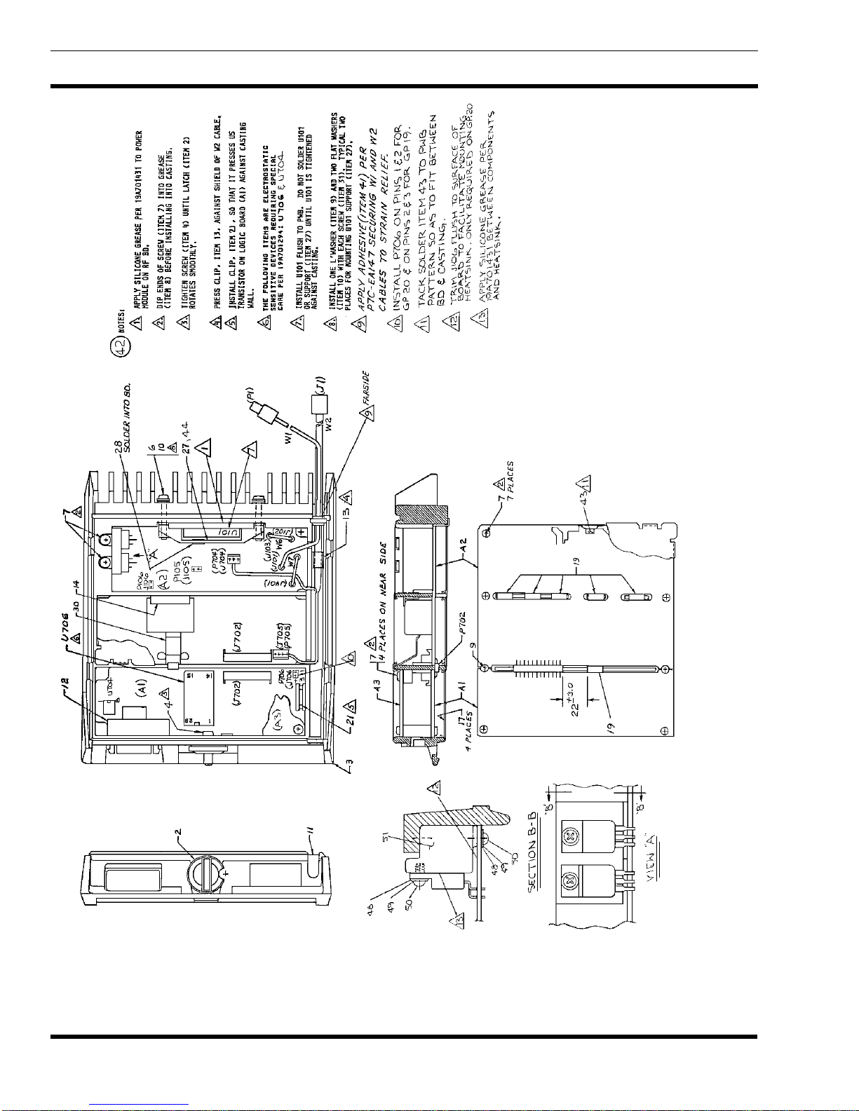
LBI-38710 ILLUSTRATED MECHANICAL PARTS BREAKDOWN
MTD SERIES 900 MHz, 10 WATT
DATA ONLY MOBILE RADIO
(19C851519, Sh. 6, Rev. 3)
8

MECHANICAL PARTS LIST LBI-38710
MTD SERIES
900 MHz, 10 WATT
DATA ONLY MOBILE RADIO
19C851519G20
SYMBOL PART NUMBER DESCRIPTION
— — — CIRCUIT BOARDS — —
A1 19D902151G3 Logic Board, MTD.
A2 19D902132G3 RF Board, MTD.
A3 19D902304G2 Audio Board, MTD.
— — — ASSOCIATED PARTS— —
1 19B801359P5 Connector. (P702).
2 19A705301P3 RF Cable. (W1).
3 19C851497P2 Power Cable. (W2).
4 19C851505P2 Latch.
5 19D901728G1 Radio Casting.
6 N130P1206B6 Screw, thread forming: No. 6-20 x 3/8.
7 N402P37B6 Flatwasher: No. 6.
8 19A702364P420 Machine screw, TORX®DRIVE:
M3.5 x 20.
9 19A702381P508 Screw, thread forming: No 3.5-0.6 x 8.
10 19A700033P6 Lockwasher, external tooth, M3.5.
11 19A701312P5 Flatwasher: M3.5
12 19C851497P2 Dummy plug.
13 19A704941P1 Dust cap.
14 19A704943P1 Clip.
15 19A704944P1 Clip.
16 19A704889P1 Nameplate.
17 19C851442P1 Cover. (Quantity 3.)
*COMPONENTS, ADDED, DELETED OR CHANGED BY PRODUCTION CHANGES
9
Table of contents
Other Ericsson GE Radio manuals

Ericsson GE
Ericsson GE MDX/ORION User manual

Ericsson GE
Ericsson GE LBI-31932E User manual

Ericsson GE
Ericsson GE EDACS FMD User manual

Ericsson GE
Ericsson GE MDS User manual

Ericsson GE
Ericsson GE FMD LBI-38609A User manual

Ericsson GE
Ericsson GE LBI-38378C User manual

Ericsson GE
Ericsson GE MDX User manual


