Ernex AS MaxiCut 1500 User manual

1

2
CONTENTS
1. Safety instructions 3
2. General instructions/Dust and Noise 4
3. Directions for assembly/Power Supply 5
4. Control functions/Transport 9
5. Operation 10
6. Maintenance/Repair 14
7. Troubleshooting 16
8. Warranty 17
9. Technical data 18
10. Standard/optional equipment 19
11. Spare part list/drawings 20
12. Wiring diagaram 25
13. Conformity declaration 26
14. Product marks 27
Original Manual: Norwegian 520102

3
1. SAFETY INSTRUCTIONS
1. This machine is designed and constructed by Ernex AS and has been submitted for test
and found in conformity with the Machine Directive 2006/42/EF, 2006/95/EF and EN 1870-5:
2002.
2. The Health and Safety at Work places duties on designers, manufacturers and supp-liers to
ensure that among other things: 1. articles supplied for use at work are, so far as is reason-
ably practicable, safe and without risks to health during setting, cleaning and maintenance
and 2. persons supplied with the articles are provided with ade-quate information about the
use for which they are designed and about conditions necessary to ensure that they will be
safe and without risks to health.
3. These duties will apply to you if you re-supply the machine by way of sale, lease, hire or hire
purchase.
4. Persons who install this machine for use at work have a duty under the Health and Safety
at Work to ensure, so far as is reasonably practicable, that nothing about the way in which it
is installed makes it unsafe or a risk to health at all times during setting, use, cleaning and
maintenance. This includes such aspects as correct assembly, electrical installation, con-
struction of enclosures, fitting of guards and exhaust ventilating equipment. When installing
this machine, consideration must be given to the provision of adequate lighting and working
space.
5. This machine is supplied complete with all necessary safeguards to enable the user to
comply with the Woodworking Machines Regulations and the Provision and use of Work
Equipment Regulations. Details of correct installation and use, together with guidance on
fitting and proper adjustment of guards are described in this manual.
6. The Woodworking Machines Regulations place absolute legal duty on employers and em-
ployees to ensure that guards and the Provision and use of Work Equipment Regulations and
any other safety devices are securely fitted, correctly adjusted and properly maintained.
7. Repairs and maintenance must only be undertaken by competent technicians. Ensure that
all power supplies are isolated before maintenance work commences. Instructions for routine
maintenance are included in this manual.
8. Machine operators must have received sufficient training and instructions as to the dangers
arising in connection with the machine, the precautions to be observed and the requirements
of the Woodworking Machines Regulations which apply, except where they work under the
adequate supervision of a person who has a thorough knowledge and experience of the
machine and the required safeguards.
9. Persons under the age of eighteen years must have successfully completed an approved
HSE course of training before operating this machine at work, unless participating in a course
of training under adequate supervision. (NB. This paragraph is only relevant to: circular
sawing machines, any sawing machine fitted with a circular blade, any planing machine for
surfacing which is not mechanically fed or any vertical spindle moulding machine).
The saw can be used for sawing wood, plywood and chipboard.
The saw must not be used on plasterboard, polysterene and tarred paper (for roofing).
WARNING: Safety equipment such as riving knife, blade guard and push sticks must not be
removed, but have to be used.

4
2. GENERAL INSTRUCTIONS
2.1 General safety precautions:
• IMPORTANT! According to the CE-regulations, rollertables must always be used.
• IMPORTANT! Note that the sawblade moves up and forward the entire length of the
slot. This is the essence of the MaxiCut concept.
• Ensurethatthereisadequateroomaroundthesaw.
• Forbeststability,placesawonalevelandevensurface.
• Keepsawtable,sawbladecoverandareaaroundsawfreeforoffcutsandexcessive
sawdust.
• Theworkingareashouldbewellventilatedandasawdustextractororcollectormustbe
used.
• Usegoodlightingandadequatehearingandeyesightprotection.
• Whensawinglongerpiecesusetheextraoutfeedtableorsuitablesupport.
• Alwayslowertopguardwhensawing.
• Usepushstickswhenrippingsmallmaterialsandwhenthedistancebetweensawblade
and rip fence is less than 120 mm (approx. 5”).
• Whentiltingthesawblade,theblademustalwaysbeloweredunderthetableandthe
motor should be switched off.
• Lowersawbladewhennotinuse.
• Alwaysuserivingknife.
• Disconnectmaincablewhenchangingsawbladeorperformingothermaintenancework.
• Useonlycarbide-tippedsawbladewhichisproperlysharpened.Neveruseacrackedor
deformed sawblade.
• Thesawisequippedwithanautomaticmotor-brake.Ifthesawcontinuestorotatefor
more than 10 seconds after the off-button has been pressed, the braking mechanism
must be replaced.
• Ensurethatthesawbladecoverisclosedaftersawbladehasbeencleanedand/or
changed or if riving knife has been changed or adjusted.
• Wornaluminiumedgingstripsinturntableshouldbereplaced.
Dust and noise:
Dust and noise measurements have been performed for work with the materials and saw
blades for which the machine is intended (see section 1 Safety Instructions).
Measurement uncertainty is related to local conditions and can vary with the saw blade/
transmission characteristics. Follow the maintenance instructions (see Section 6 Mainte
nance/Repair).
Ear protection must be used, and a dust mask is recommended.
For indoor use, the machine must be connected to an extractor
that provides a minimum air speed of 30 m/s i.e. 1.8 kPa.

5
3. DIRECTIONS FOR ASSEMBLY
3.1 Top guard adjustment
• Adjustthetopguard(Fig. 2) so that the wooden strip on the inside of the guard
is 3 mm from the saw blade. See Fig. 1.
3 mm (1/8")
Fig. 1
Fig. 2

6
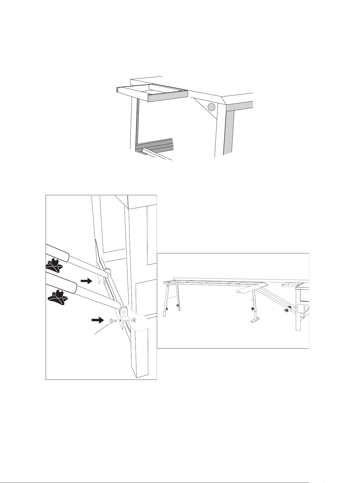
3.2 Mounting rollerbox and adjustable rollertable
• Attachguidebartosawbyturninglockinghandle.See Fig. 3.
• RemovestopscrewAat the end of the guide bar and insert the end of the roller-
box into the guide bar. Retighten stop screw A.
• Setuprollertablesupporttrestleandadjustatapproximateheight.Attachthe
rollertable to the rollerbox with screws. Now adjust correct trestle height L
Fig. 3a.
• Adjustrollerboxheight,bringingitushwiththeturntablebylooseningthelock-
nuts on the guide bar fastening screws B, adjusting the screws and locknuts
Fig. 3. Check rollerbox height by laying the rip fence across the turntable, roller-
box and rollertable. Tighten the locknuts and re-check the height.
• FitripfenceasillustratedinFig. 4a/4b.
• AdjustguidebaranglebymeansofscrewsB. Set turntable at 90° and use a
carpenter’s square to check the angle between the rip fence and the sawblade
Fig. 4b. Tighten screws and re-check angle Fig. 3.
A
B
C
C
Fig. 3
L
Fig. 4a
Fig. 3a
Fig. 4b
7
3.3 Attaching support roller
• AttachsupportrollertothesawusingM10x16screws.SeeFig. 5.
Fig. 5
3.4 Assembling the fixed table w/board support
Assemble as illustrated in Fig. 6a/6b.
M10 x 16
Fig. 6a
Fig. 6b

8
3.4 Connecting mains supply - direction of rotation
• Whenconnectingasawwithathree-phasemotortothemains,checktosee
that the sawblade rotates in the right direction (away from the riving knife). The
direction of blade rotation is indicated on the sawblade cover under the table.
If the blade rotates in the wrong direction, two of the phases must be switched.
This should be done by an electrician. Three-phase saws which run on 400 V
have a change of phase switch which is operated by a screwdriver. These saws
are fitted with a neutral wire, i.e. 5-prong plugs. Note the placement of the neutral
prong in Fig. 7. Check also to see that the blade is mounted correctly with re-
gards to the direction of rotation.
• NOTE! For single-phase motors, supply cables must have at least 2.5 mm2
conductors. Recommended cablelength max. 20 feet.
• Extensioncordsmusthavegroundprotection.
• For3-phasemotors,thisdimensionisrequiredforcablesover10feetin
length.
S2 T3
R1 N
3P+N+
Kobl. 400V (5 pins)
Fig. 7
9
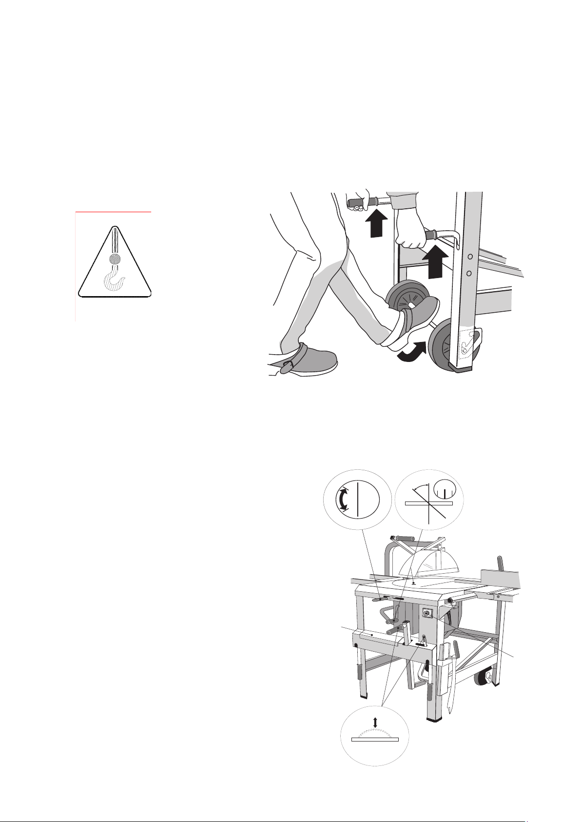
4. CONTROL FUNCTIONS/TRANSPORT
4.1 Raising and lowering transport wheels
• Topositionthewheelsfortransport,liftthesawbythehandlessothattheaxle
drops into the bottom notch, and lower the saw again.
• Thesawshouldnotbeleftstandingonitswheelsduringmotorvehicletransport
orwhileinuse.Liftsawandpushaxleupintothenotchtotherear.SeeFig. 8.
4.2 Accessories
• OnthefrontofthesawisatoolboxG
which may be locked.
• Thesawisprovidedwith4handlesfor
lifting.
• Oneofthesawlegshasareceptaclefor
push sticks.
• Whenliftingthesawwithacrane,place
slings in the holes on either side of the
saw.
4.3 Starting and stopping motor
An On/Off switch Cis located on one of the legs.
A cover which can be locked with a padlock is
mounted over the switches. See Fig. 9. Incor-
porated into the switch is a zero-voltage switch
which prevents the motor from starting unexpect-
edly after a power-out. If the motor is overloaded,
the built-in overload feature will disconnect the
power. After a short cooling-off period the motor
may be started again by pressing the start but-
ton. Avoid overloading the motor.
D
E
20
0°
45°
C
F
G
Fig. 8
Fig. 9
10
4.4 Raising and lowering saw blade
The saw blade is raised and lowered by means of the elevation arm illustrated in D,
Fig. 9. The blade may be locked at the desired height by means of the elevation locking clamp
illustrated in D, same figure.
4.5 Tilting saw blade
Thesawblademustbeinlowpositionwhenadjustingtiltingangle.Loosentiltinglocking
clamp Fto tilt saw blade from 0° to 45°. See Fig. 9. The angle of tilt is indicated on the
scale in the turn table.
4.6 Turning turn table
The turn table may be turned horizontally from 0° (ripping) to 135°, though it is limited to
90° when the short rollertable is attached. The angle is indicated by means of a scale on
theturntableandamarkonthesawtable.Lockturntableindesiredpositionbypush-
ing stop handle Eto the left. Free turn table by pushing stop handle to the right. The saw
is also provided with pre-stops at 0° - 45° - 90° and 135°. See Fig.9.
5. OPERATION
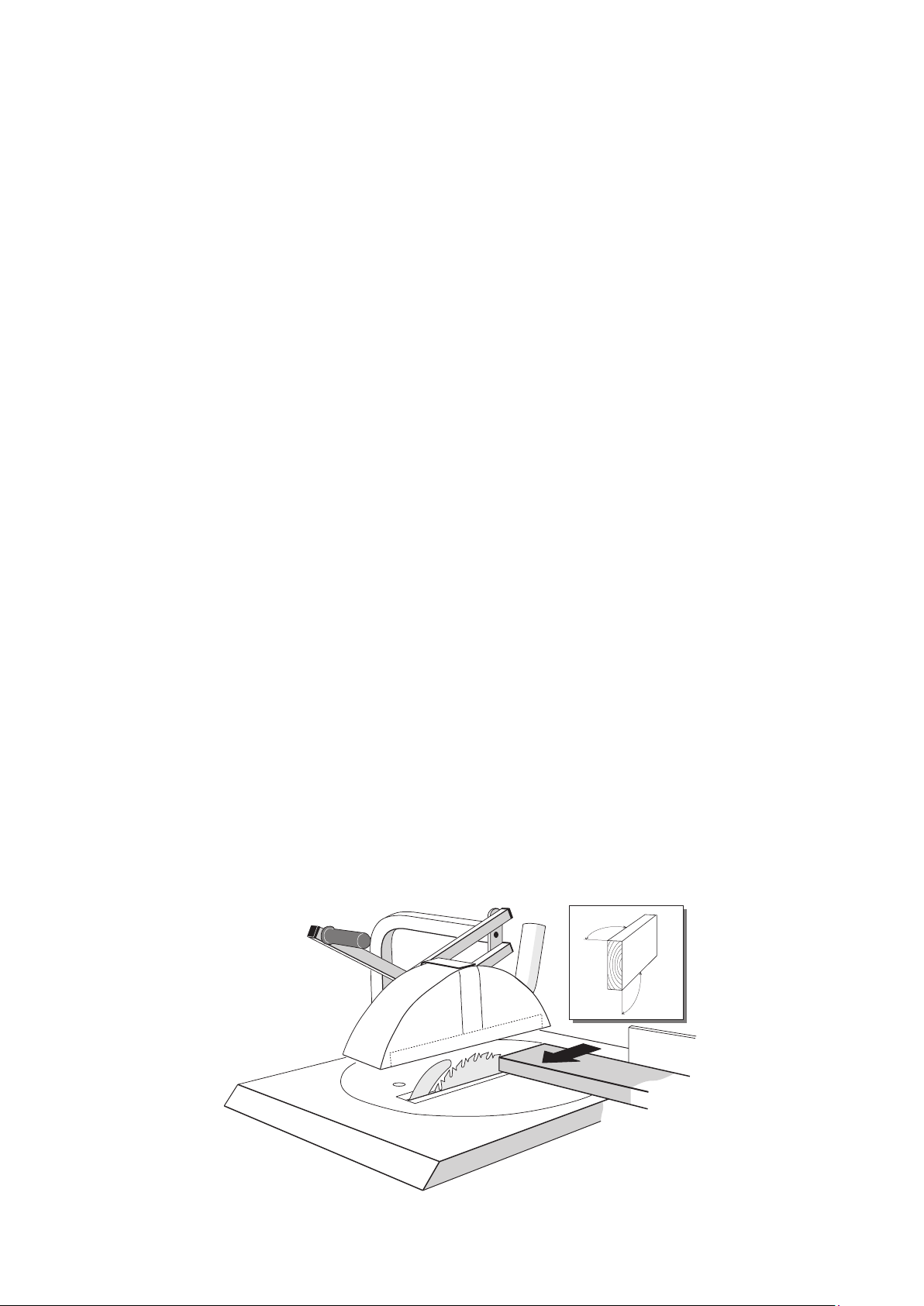
5.1 Crosscutting
There are two methods for making crosscuts (with the turntable at 90°).
A • Holdmaterialagainstfenceandraisesawbladetomakecut.
IMPORTANT! Note that the saw blade moves up and forward the entire length
of the slot. This is the essence of the MaxiCut concept.
B • Raisesawbladetodesiredheightandlockintoplace.Placematerialagainst
fence behind saw blade and feed material into sawblade by pulling fence.
See Fig. 10.
CAUTION! Crosscutting as described in Bcan only be done with saw blade set
at a 90° angle. Never saw more pieces at one time than can be held securely
against the fence.
CAUTION! Never stack boards higher than the rip fence provides support for.
90°
90°
Fig. 10
11
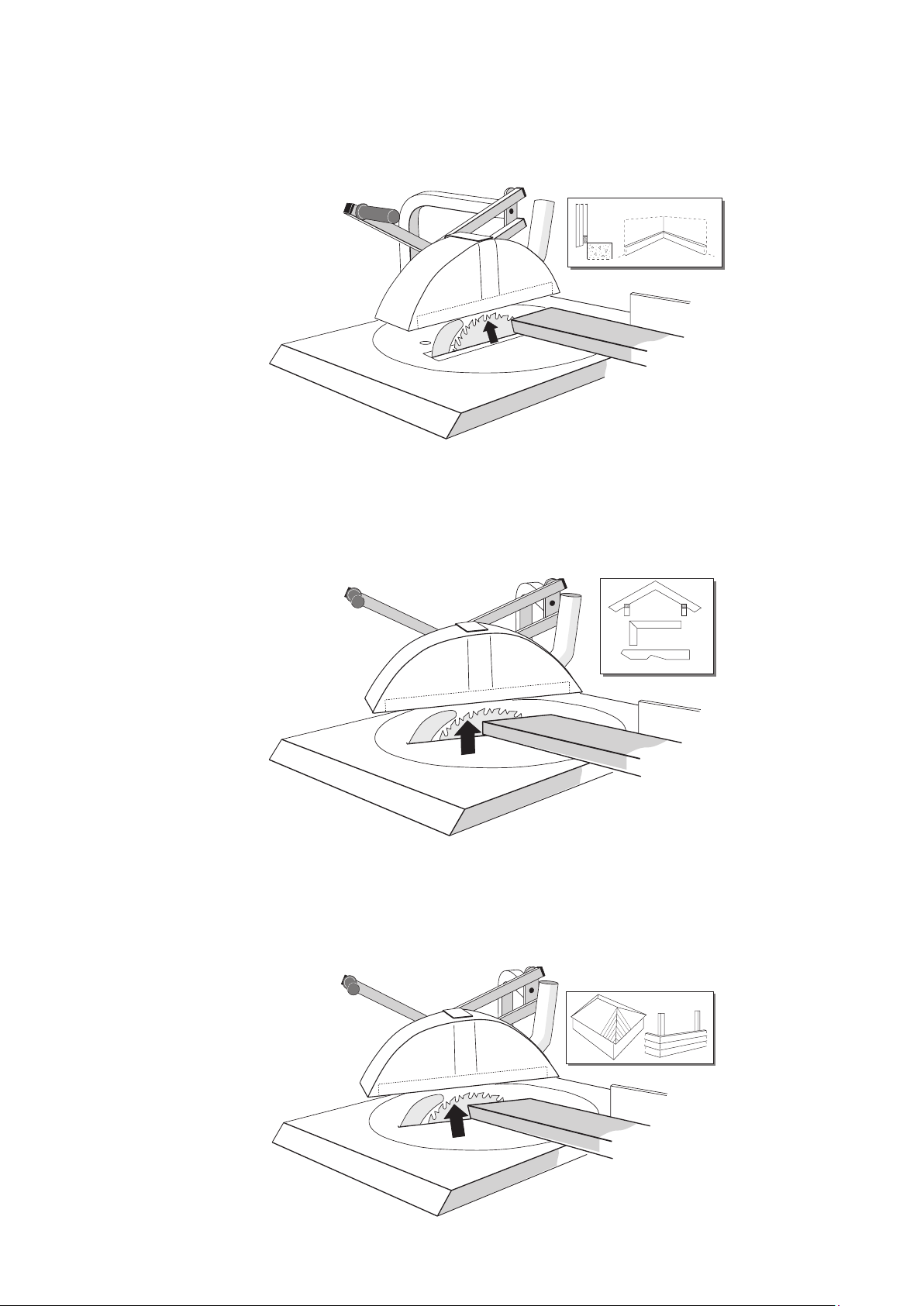
5.2 Bevelled crosscutting (tilted blade)
• Tiltsawbladetodesiredangleandtightenlockingclamp.
• Placematerialagainstfenceandcutbyliftingsawblade.See Fig. 11.
5.3 Angled crosscutting
• Turnturntabletodesiredangleinrelationtofence.
• Holdmaterialagainstfenceandcutbyliftingsawblade.See Fig. 12.
5.4 Compound angle cutting
• Setturntableasforanangledcrosscut.
• Tiltsawbladetodesiredangleandlock.
• Holdmaterialagainstfenceandcutbyliftingsawblade.See Fig. 13.
Fig. 11
Fig. 12
Fig. 13

12
5.5 Ripping
• Locksawbladeatdesiredheight.Theblademustbeparalleltothefence.
• Positionthefencelengthwisesothatitsendisinlevelwiththecentreofthesaw-
blade.
• Lockfenceatdesireddistancefromsawbladetoobtainwidthrequired.
• Feedmaterialalongfenceandintosawblade.Usepushstickswhenthedistance
between sawblade and fence is less than 120 mm (5”) and the remaining length is
less than 120 mm (5”). See Fig.14.
5.6 Ripping with bevelled cuts
• Setturntableandfenceforrippingandadjustsawbladetodesiredverticalangle
and lock. Perform operation as described in 5.5. See fig. 15.
5.7 Cutting grooves lengthwise
• Setsawbladeinverticalposition,raiseandlockatdesiredheight.Theblademustbe
parallel to the fence.
• Lockfenceatdesireddistancefromsawblade.
• Feedmaterialalongfencetowardsthesawblade,usingpushstickswhenthe
distance between fence and sawblade is less than 120 mm (5”) and trailing end of
material is less than 120 mm (5”) from sawblade.
• Adjustfenceandrepeatoperationuntilgrooveistherequiredwidth.See Fig. 16.
Fig. 14
Fig. 15

13
5.8 Cutting rabbets and grooves across material
• Settheturntableat90°tothefenceandlockthesawbladeatthedesiredheight.
• Holdmaterialagainstthefenceandfeeditthroughthesawbladebypullingthe
rollertable towards you.
• Advancematerialslightlyalongthefenceandrepeattheoperationuntiltherab-
bet or groove has the proper width. See Fig. 17.
Fig. 16
Fig. 17

14
6. MAINTENANCE/REPAIR
CAUTION! Make sure power supply is disconnected while performing mainte-
nance operations. A minimum of maintenance is required to ensure satisfactory
performance and a long service life.
• Lubricatemovingparts,linkagesandthebearingscarryingtheturntableatregu-
lar intervals. It is also important to lubricate the moving rings at the ends of the
sawblade spindle.
• Checkallscrewsandnutsregularlyfortightness.
• Topguardshouldbeclean.Ifdamageditshouldbereplaced.
• Keepsawandsawbladecoverfreefromsawdust.Payparticularattentiontomo-
tor ventilation openings and cooling fins.
• Keepsawbladecleanandinorder.Replacebladeifthereareanycracksor
missingteeth.Removeresindepositswithasuitablecleaninguid.
• Thesawisequippedwithanautomaticmotor-brake.Ifthesawcontinuestoro-
tate for more than 10 seconds after the off-button has been pressed, the braking
mechanism must be replaced.
• Thesawmaybeconnectedtoasawdustextractorwithaminimumcapacityof
1100 m3/h.
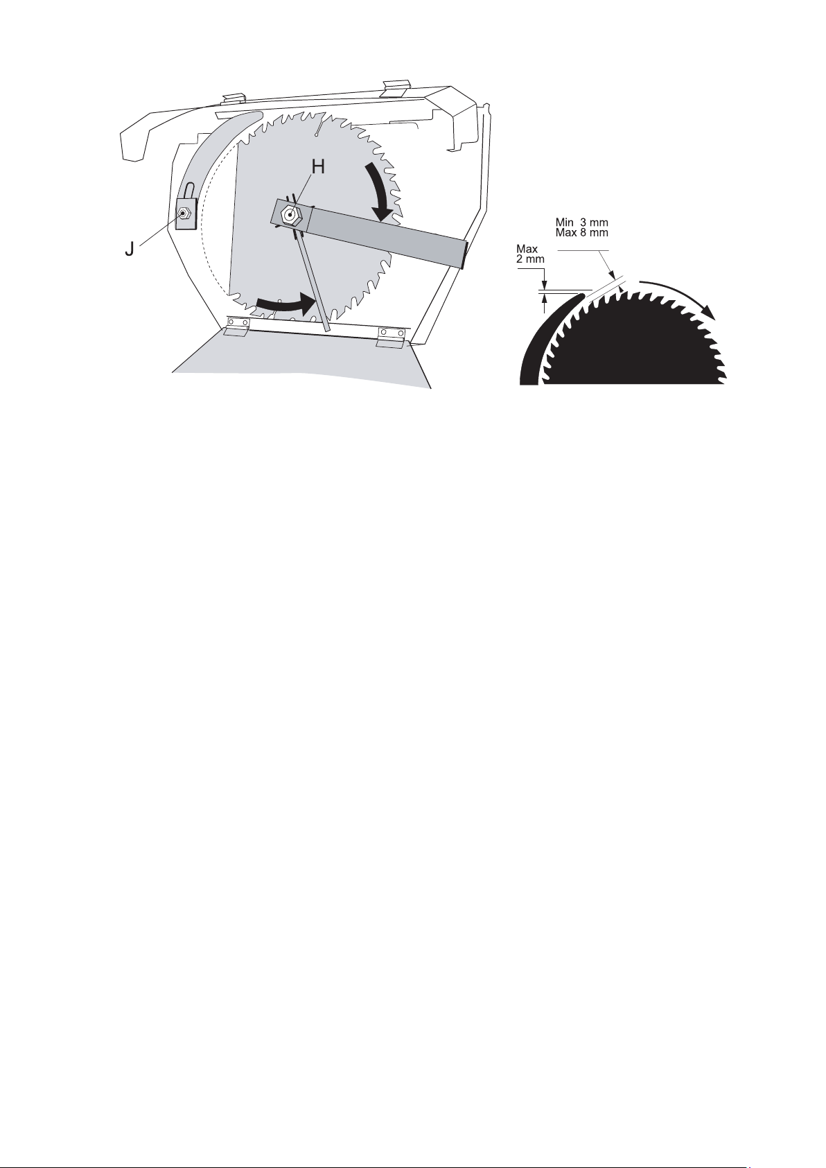
6.1 Replacing sawblade
• Sawblademustbeinlowerpositionwhenbeingremoved.
• Usetoolstoopensawbladecover.Restrainuppercoverusingchainundersawta-
ble.Usetoolssuppliedwithsawtoremovesawblade.ArbornutHhas a left-hand
threadandisunscrewedbyturningclockwise.Useanothertooltokeepsawb-
lade from rotating while removing arbor nut. Close cover when finished. See Fig.
18.
6.2 Replacing and adjusting riving knife
• Therivingknifemustalwaysbettedwhenthesawisbeingused.Adjustriving
knife as illustrated in Fig. 18 and 19.
• Whenreplacingsawbladewithabladeofadifferentthickness,therivingknife
mustbereplacedaswell.LoosennutJ to free riving knife. The thickness of the
riving knife should be 0.2 mm wider than the kerf width of the sawblade. Be sure
to close the saw blade cover when finished.
6.3 Replacing top guard and push sticks
• Thetopguardandpushsticksareimportantsafetyfeatureswhichmustbe
replaced immediately if damaged in any way.
15
Fig. 18 Fig. 19
REPAIR
Routines at repair:
* The machine must only be repaired by qualified electricians or authorised
service workshops.
Testing the brakes:
* The brake for the saw blade rotation should be tested regularly.The stop-time
must be max. 10 sec. Start/stop the saw 10 times in a row and check the
stop-time.

16
7. TROUBLESHOOTING
The saw does not start:
* check the power supply
* do not use the cable with several machines at the same time
* check that the cable is not too long, and that the cross-section is not too small
* contact an electrician
The saw vibrates and is weak
* check that the blade box under the bench does not contain chips and sawdust
* check the spindle
* check the saw blade for eccentricity, and that all the teeth are whole and sharp
* check that the motor brake is clean and that it loosens when starting up, clean
it by removing the fan cover and for instance use compressed air to purify.
The saw blade is heavy to lift and does not go down completely
* check that nothing is stuck in the blade box
* check that the bearings in the universal joint and the movable glide rings at either
end of the spindle are not stuck

17
8. WARRANTY
Notwithstanding any statutory requirements, Ernex AS provide warranty in accordance with the
legislation of the customer‘s own country of residence, but in all cases for a minimum of 3 years,
except for electrical parts which still has a 1-year warranty commencing from the date on which
the machine is sold to the end user. Ernex AS/The importer promise to repair, or at our op-
tion, replace with like grade and quality any product determined to be faulty due to the failure of
parts, material or workmanship.
The warranty covers defects in material and/or workmanship only. When making a claim under
the warranty, proof of purchase bearing the original date of purchase must be submitted. The
repairs under warranty may only be carried out by Ernex AS, or by authorized Ernex warranty
service agents or the importer.
The warranty will not apply in cases of:
- incorrect use, overloading of the machine or fitting non-approved accessories
-useofforce,damagecausedbyexternalinuences,orforeignbodies
- damage caused by non-observance of the instructions for use, such as connection to an
unsuitable mains supply or voltage or non-compliance with the installation instructions
- normal wear and tear
The warranty also does not cover machines which have been partially or completely dismantled.

18
9. TECHNICAL DATA
MaxiCut 1500
Manufacturer: Ernex AS, Norway.
NS-ISO 9001
Model: Norsaw MaxiCut 1500.
Table: 650 mm x 790 mm.
Height: 885 mm.
Weight: 124 kg.
Sawblade: Carbide-tipped, Z=32.
Diam. 360 mm.
Arborhole30mm.(USA31.75mm.)
Kerfwidth3.5mm.
Riving knife: Hardened steel, thickness 3.0 mm.
Cutting height: 104 mm at 90° (vertical)
80 mm at 45° (tilted).
Motor: 2.2 kW-230V single phase.
1.6 kW-110V single phase.
2.2 kW-230/400V three phase.
Motorspeed: 2700rpm.(USA3240rpm.)
Peripheralspeed: 52.5m/swithstandardblade.(USA58m/s.)
Cable dimension: Single phase: minimum 2.5 mm2
max length: 15 m
Three-phase: minimum 1.5 mm2.
Fuse: 230V single phase 16 A time-lag
230V three phase 13 A time-lag
110V single phase 25 A time-lag
400V three phase 10 A time-lag
Motor protection: 230V single phase: 16 A
110V single phase: 20 A
230V three phase: 12 A
400V three phase: 7 A
Thermoelement: Thermal relay in motor 140° Celsius
Noise as per 2006/42/EC: No-load: 85,0 dB.
Loaded:87,5dB.
-certification: Certified by Dansk Teknologisk Institut,
Aarhus. Identification number: 0396,
approval certificate number TI-09-MD-0311.

19
10. STANDARD EQUIPMENT
• GuideBar
• Rollerbox
• Supportroller
• Carbide-tippedsawblade
• 2pushsticks
• Topguard
• Wheels
• Handtools
OPTIONAL EQUIPMENT
• Adjustableinfeedrollertablewithsupporttrestle
• Fixedoutfeedrollertablewithboardsupport
• Aluminiumfencewithlengthstopforadjustableinfeedrollertable
• Aluminiumfenceforxedoutfeedrollertable
• Telescopeextension
• Shortaluminiumfence
• Sawdustextractor
• Fittingsandexiblehoseforsawdustextractor
Standardequipmentmayvaryineachcountryduetocurrentlegislation!
* According to the CE-regulations rollertables must always be used.

20
2011
Ernex AS Spare Part List Gjerde 1500
Pos. Art.No. Text
1 720 101 Saw frame
2 720 078 Tabletop
3 720 242 Foot
4 720 008 Turntable
5 720 224 Packing strips R/L (2)
6 720 252 Guide bar
7 720 271 Guide bar w/brackets compl. (10/05-)
8 720 320 Bracket f/guide bar (1)
9 745 746 Measure f/guide bar
10 745 901 End plug f/guide bar
11 745 927 Roller box compl. (91-)
12 717 548 Handle
13 745 919 Guide roller w/bearings (4)
14 745 965 Caster w/screw f/roller box (1)
15 720 205 Nut w/screw f/guidebar
16 745 685 Adjustment bolt M8x35
17 745 961 Indicator f/roller box
18 745 960 Locking system f/roller box compl.
19 720 185 Ball jointed arm
20 745 929 Handle f/r.box locking
21 720 075 Plastic sleeve 25x5 (93-99)
22 745 959 Fixing brackets f/roller box
23 720 226 Bracket f/ball jointed arm
24 707 710 Short work support compl.
25 707 711 Roller
26 720 168 Elevation frame
27 720 222 Elevation arm compl.
28 720 221 Sleeve nut
29 720 181 Handle top guard (short) compl.
30 720 073 Plastic sleeve Ø22 f/elev.arm (99-)
31 720 248 Roller f/elev. arm
32 720 287 Arm f/turntable lock
33 720 288 Lifting handle (bent)
34 720 286 Lifting handle (99-)
35 707 019 Hook f/push stick
36 720 329 Bracket f/push stick
37 720 098 Pre-stop
38 720 155 Handle f/pre-stop
39 720 264 Pre-stop arm f/tilting
40 720 253 Spring f/pre-stop
41 720 321 Ball bearings f/turntable (7)
42 720 107 Turntable locking bolt
43 720 108 Bracket f/turntable lock
44 707 398 Brass pc. f/locking screw
45 720 092 Tilting scale
46 720 228 Glass lens
47 720 292 Tilting scale compl.
48 720 195 Tilting device
49 720 200 Bracket f/tilting scale
50 720 104 Eccenter disk
51 707 604 Suction connector w/rivets
52 720 276 Upper guard compl.
53 720 274 Hood w/dust conn.
54 720 174 Guard arm compl.
55 720 144 Bracket f/upper guard
56 720 172 Adjusting bars
57 720 260 Riving knife 3mm -Std.
58 720 245 Riving knife bracket
59 720 259 Clamps & bolts f/riving knife
60 720 347 Clamp f/sawblade, inner
61 720 396 Clamp f/sawblade, inner EMG
62 820 165 Clamp f/sawblade, outer
63 820 166 Spindle nut (left handed)
66 720 390 Motor 230V/1-ph. 2kW EMG
67 720 391 Motor 230V/3-2.2kW EMG
68 720 392 Motor 400V/3-ph. 2.2kW EMG
69 720 393 Motor 110V/1-ph. 1.6kW EMG (-01)
70 720 394 Motor 230V/1-w/o switch & susp. EMG
71 720 397 Motor 400V/3-w/o bracket EMG
72 720 398 Motor 230V/3-w/o bracket EMG
73 720 019 Bracket f/motor
74 720 231 Bracket nut f/motor
75 720 261 Spring f/elev. arm
76 720 013 Suspension f/motor
77 720 156 Connecting arm f/motor
78 720 160 Connecting arm w/nut
79 720 090 Capacitor 40MF Hanning
80 720 091 Capacitor 110MF Hanning
81 720 333 Capacitor 120MF
82 708 333 Capacitor 40MF EMG
83 720 336 Brake EMG
84 720 348 Motor brake f/Hann. motor
85 720 335 Fan EMG
86 720 349 Fan f/Hann. motor
87 720 350 Fan cover f/Hann. motor
88 720 794 Fan cover EMG
89 720 060 Switch 230V/1-ph. 2.2kW K&B
90 720 061 Switch 230V/3-ph. 2.2kW K&B
91 720 062 Switch 400V/3-ph. 2.2kW K&B
92 720 063 Switch 110V/1-ph. 1.6kW K&B
93 720 099 Switch plate
94 708 018 Switch cover 6x6cm K&B (-06/01)
95 708 020 Switch cover K&B (06/01-) w/PVC cove
96 708 076 Relay 2.2.kW K&B
100 720 409 Blade cover Ø360 complete
101 720 405 Blade cover (01-)
102 720 306 Blade cover (-99)
103 720 386 Blade cover (00-)
104 720 268 Cover plate (-99)
105 720 388 Cap f/blade cover (00)
106 720 071 Safety plate
107 720 411 Cover plate outside
108 720 382 Cover plate inside
109 720 176 Height locking clamp
110 720 293 Tool box compl.
111 720 097 Cover f/tool box
112 720 139 Tilting handle
113 720 210 Mounting hinge front
114 720 002 Mounting hinge rear
115 720 163 Wheel shaft
116 720 161 Wheel device R.
117 720 162 Wheel device L.
118 720 072 Wheel (1)
119 720 395 Locking device, set (4)
120 720 265 Tool f/Hanning motor
144 707 328 Push stick
145 745 099 Push stick
146 820 134 Tool f/arbor nut
147 717 555 Spindle tool
148 720 305 Carton w/std. parts
149 720 376 Handle f/tilting (long)
170 708 789 Sleeve f/ball jointed arm
Table of contents
Other Ernex AS Saw manuals


