Ernex AS Norsaw 250 User manual


2
CONTENTS
Side
1. Safety instructions 3
2. General instructions/Dust and Noise 4
3. Mounting/Power Supply/Transport 6
4. Functions 10
5. Operation 12
6. Maintenance/Repair 14
7. Troubleshooting 16
8. Warranty 17
9. Technical data 18
10. Standard/Optional equipment 18
11. Spare part lists/Drawings 19
12. Wiring diagram 23
13. Product Marks 24
14. Conformity declaration 25
Original manual: Norwegian 525053

3
1. SAFETY INSTRUCTIONS
The European Union Machinery Directive 2006/42/EF, 2006/95/EF and EN 1870-5:2,
requires manufacturers, importers, suppliers and dealers to ensure that machines are
designed and built to avoid causing injury to users and others by accident or inappropri-
ate work posture or strain. Machinery used at a workplace must - wherever practicable - be
secured and pose no risk to operator health during installation, operation, cleaning or mainte-
nance.
Persons who will use the equipment must receive the necessary information on operation,
usage and precautions necessary for safe operation without risk to life or health.
The Directive applies to purchase, resale (wholesale, retail), leasing, short and extended
hire, and hire-purchase.
Persons installing the machines at a workplace are required under the regulations to ensure
that - wherever practicable - no aspect of the installation has rendered the machine unsafe
or causes it to pose a hazard at any time during assembly, use, cleaning or maintenance.The
Directive also covers assembly, electrical hookups, accessories, safety features and extrac-
tor fans/ ventilators. Make sure there is sufcient light and space before commencing instal-
lation.
The Norsaw 2003 comes complete with the safety features enabling the operator to comply
with the regulations. Details on correct installation and use, combined with a guide to instal-
lation and proper adjustment of the safety systems, are described in this User Guide.It is an
absolute requirement under the Directive that the employer and employee shall ensure
themselves that all safety features are properly installed, adjusted and maintained and that
personal protective gear is worn.
Repairs and maintenance must only be done by a competent person. Be sure to check that the
power supply is off and the plug is out before starting a maintenance procedure. Instructions
for maintenance procedures are included in this User Guide.
The machine operator must receive adequate training and instruction on the hazards of the
machine and the precautions that must be observed and the actions that the law requires of
him, or alternatively must work under the close supervision of a person thoroughly familiar
and experienced with the machine who knows and understands the proper precautions to be
taken.
Persons under the age of 18 years must take and pass an approved HSE course before us-
ing the machine at the workplace except when on a training course under adequate supervi-
sion and guidance.
The saw is ideal for use with wood, plywood and chipboard.
The saw must not be used on plasterboard, polysterene and tarred paper (for roong).
WARNING: Safety equipment such as riving knife, blade guard and push sticks must not be
removed, but have to be used.

4
2. GENERAL INSTRUCTIONS/DUST AND NOISE
2.1 General safety precautions:
• IMPORTANT! According to the CE-regulations an extension table should
be used wherever possible.
• IMPORTANT! Note that the saw blade moves up and forward the entire length of the slot.
• Ensure that there is adequate room around the saw.
• For best stability, place saw on a level and even surface.
• Keep saw table, saw blade cover and area around saw free of off cuts and excessive saw-
dust.
• The working area should be well ventilated and a sawdust extractor or collector should be
used.
• Use this machine in a well lit area and wear adequate hearing and eye sight protection.
• When sawing longer pieces of timber use an extension table or suitable support.
• Always lower top guard as close as possible to the work piece when sawing.
• Use push sticks when ripping small materials and when the distance between
saw blade and rip fence is less than 120 mm (approx. 5").
• When tilting the saw blade, the blade must always be lowered under the table and the mo-
tor should be switched off.
• Lower saw blade when not in use.
• Always use riving knife (See Section 6.2 for adjusting).
• Disconnect main cable when changing saw blade or performing other maintenance work.
• Use a carbide-tipped saw blade which is properly sharpened. Never use a cracked or de-
formed saw blade.
• The saw is equipped with a motor-brake.
• Ensure that the saw blade cover is closed after the saw blade has been cleaned and/or
changed or if riving knife has been changed or adjusted.
• For ripping, always push saw blade to rear of slide travel and lock it in position, before
rotating the table and the blade to the ripping position.
• The saw should not be exposed to rain, wet- or dampness. It should be stored in a dry
environment.
• The saw must not be started close to gas or other explosives (electrical sparkles will
occur by start/stop).
• IMPORTANT! The saw blade must run freely when starting the saw.
2.2 Main connection
The saw is delivered with cable and plug (230V). 110V machines only with cable.
Supply cables must have ground protection and a conductor cross-section of 2,5
mm². Recommended length max. 25 m.

5
•Dust and noise measurements have been performed for work with the materials and saw
blades for which the machine is intended (see section 1 Safety Instructions).
Measurement uncertainty is related to local conditions and can vary with the saw blade/
transmission characteristics. Follow the maintenance instructions (see Section 6 Mainte-
nance/Repair).
Ear protection must be used, and a dust mask is recommended.
For indoor use, the machine must be connected to an extractor that provides a minimum
air speed of 30 m/s i.e. 1.8 kPa.
2.3 Dust and Noise

6
Fig. 1
3. MOUNTING/POWER SUPPLY/TRANSPORT
3.1 Mounting the saw
The saw is delivered in a carton box with the table top downwards Fig. 1.
Pull out/Unfold the legs Fig. 2 and tighten the locking wheels Fig. 3.
Fig. 3
Fig. 2
For best stability place saw on a level, even surface. If the machine still needs to be level
led, this can be achieved by adjusting one or more of the legs Fig. 4.
Fig. 4
7
Fig. 8
Fig. 7
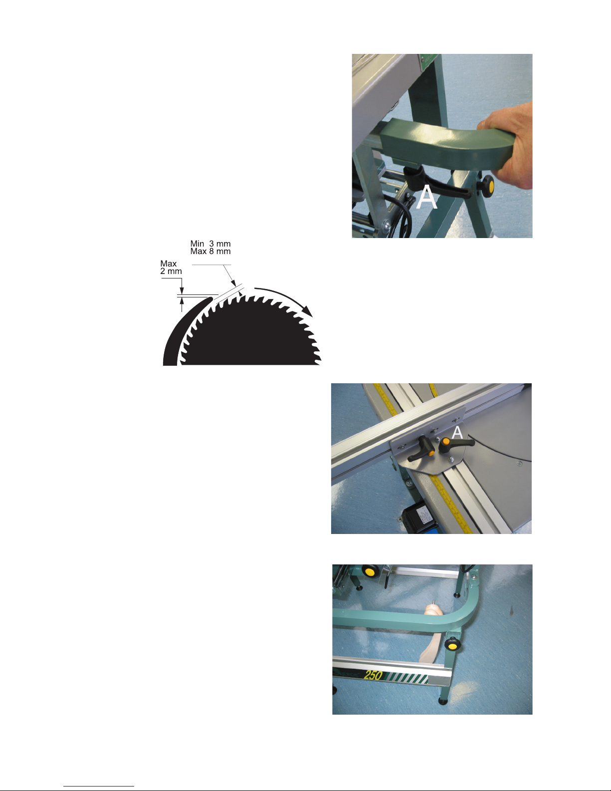
Check saw blade and riving knife and
assemble according to illustration Fig. 6.
Fig. 6
Mount the fence by loosening the handle
Aand lead the nut underneath the fence
into the slot of the aluminium prole.
Lock lever Fig. 7.
3.2 Mount the push sticks
The push sticks should be placed on the
(enclosed) hook at front of machine Fig. 8.
Mount the top guard by pushing the tube to
the bottom and make sure that the handle A
is locked into position Fig. 5.
Fig. 5

8
3.3 Mounting the tables
The same table can be used on both sides of the saw.
Length: 1 m - Weight: 3 kg
9
Fig. 9
Fig. 10
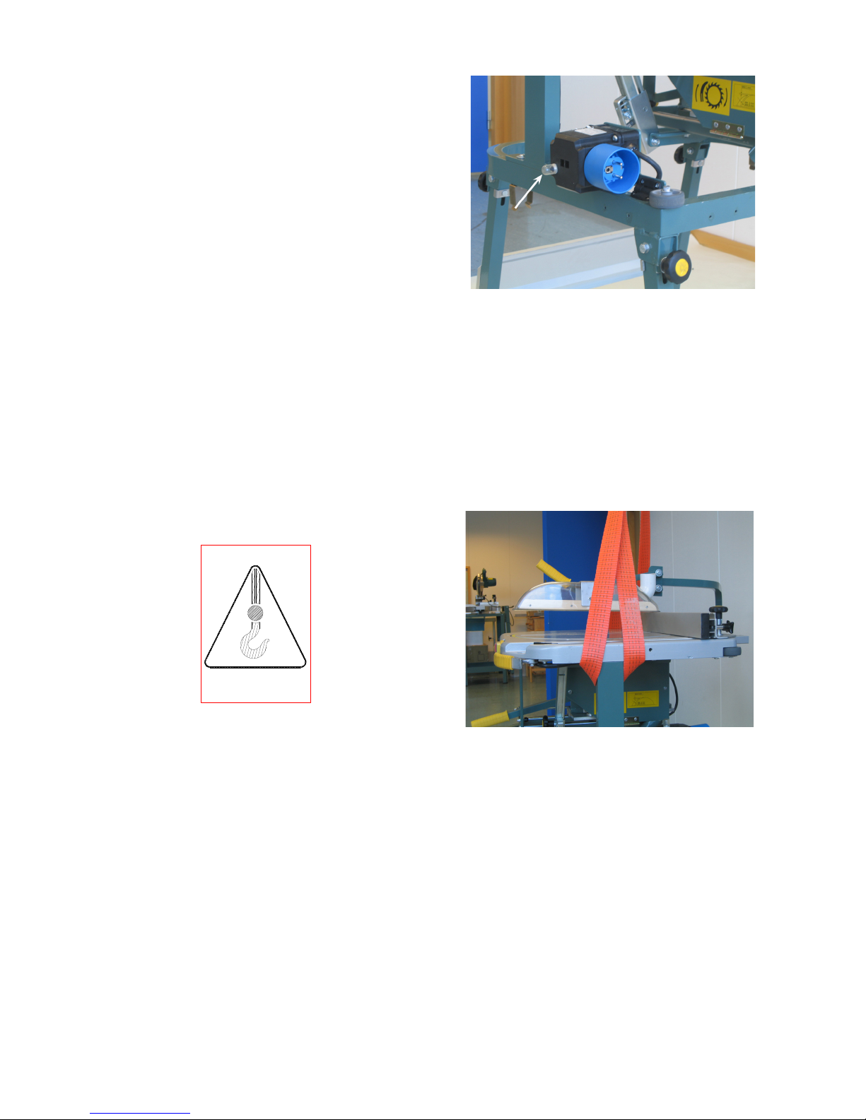
3.3 Connecting main supply
Use an approved extension cord with
ground protection/earth wire diam.
2,5 mm², max. length 25 m.
Tilt the switch and connect power supply
cable.
NB! The switch should always stay in this
position when the saw is in use Fig. 9.
3.4 Connecting of Dust Collector
A dust collector must always be connected to the top guard and the lower blade cover
when using the saw indoors. The extractor should have a capacity of at least 234 m /h -
28 m/sec. The suction connector has a diam. of 38 mm. Remember to cut off the top of
the nozzle on the top guard.
3.5 Transport - carrying-/wheel transport
When lifting the saw with a crane, place slings around the legs on either side of the
machine Fig. 10.
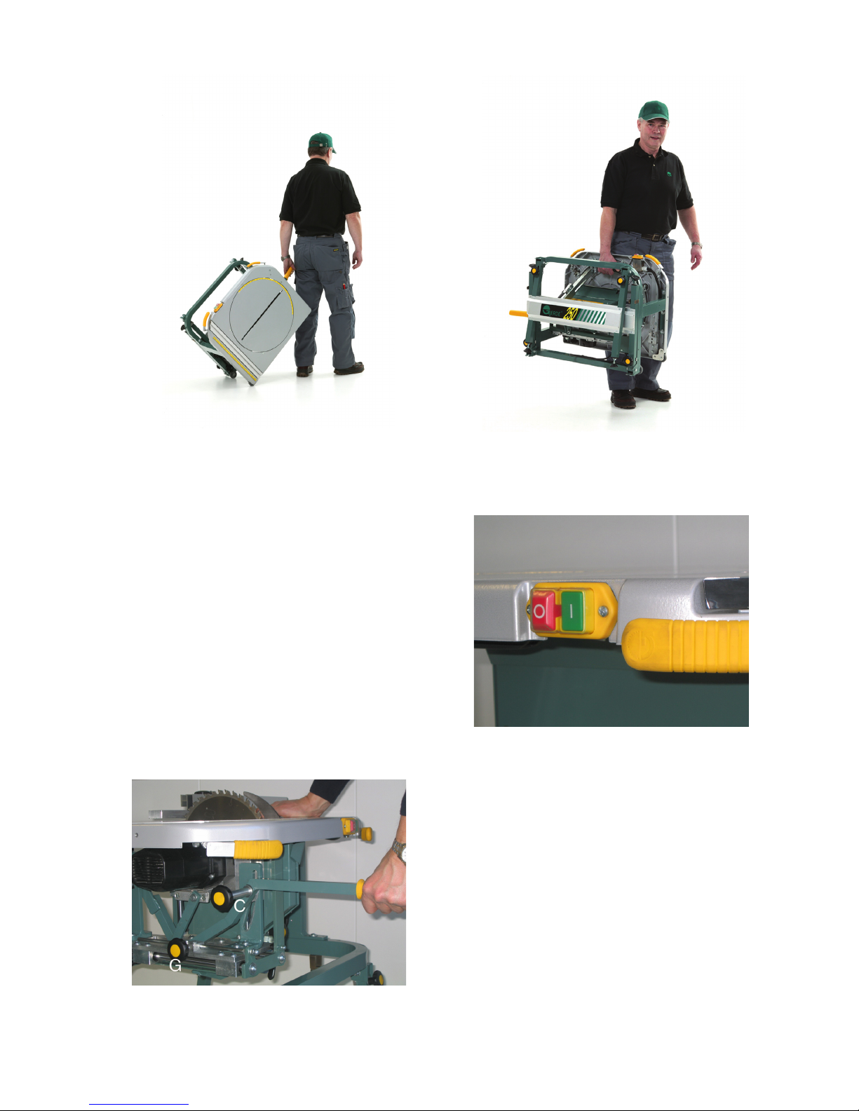
1. Remove extension table (if any) and its locking handles, also remove the push sticks.
2. Remove the fence and make sure that the alu. prole in the table top doesn't stick out on
either side.
3. Remove the top guard by loosening the handle and pull out.
4. Tilt the switch into transport position, lower the saw blade and lock it. Set the saw in
ripping position 90° and lock it in the forward position (seen from the operating side).
5. Tilt the saw down on its wheels (right side) and loosen the locking wheels on the legs.
Fold the front legs rst and secure other legs in the clips. Remember to tighten the
locking wheels.
6. You can now pull the saw by means of the handle or carry it by the black handle beneath
the table top Fig. 11 and 12.
10
Fig. 13
Fig. 14
Fig. 11 Fig. 12
4. FUNCTIONS
4.1 On/off switch
On the front side of the saw there is a green
ON- and a red STOP button. The switch has
an overload protection and a low-volt cut out
which will automatically stop the motor. If the
overload protection comes into operation, wait
until the motor cools down and restart.
Try to avoid this situation Fig. 13.
To reset the overload protection, press
the button on the plug Fig. 9.
4.2 Raising/lowering the saw blade
Loosen the lifting handle by turning the
locking wheel C. The blade can then be
lifted and lowered. It can be locked at
any height by turning the wheel Fig. 14.
11
Fig. 15 Fig. 16
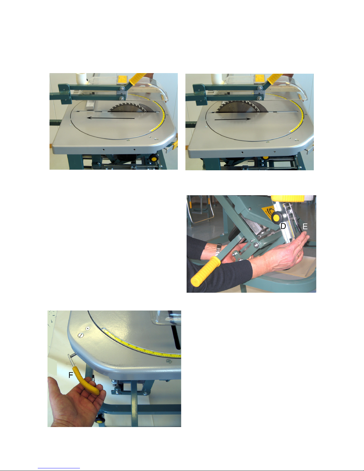
4.3 Pushing/pulling of saw blade
The blade can be pushed or pulled along the slot in the turntable Fig. 15 and 16. The
slide mechanism can be locked with the locking wheel G below the table top Fig. 14.
4.4 Tilting of saw blade
Before tilting, the blade must be lowered.
By loosening the locking wheel Dand
push the arm Efor tilt securing (position
handle), the blade can be tilted from -2° to
- 47° Fig. 17.
Position and lock the blade in desired
tilting angle. Set the degrees on the scale
and tighten the locking wheel.
Attention: Locking wheel D must also be
tightened in 0 and 45° (the pre-stop
function).
4.5 Rotating the turntable
The turntable can be rotated both ways
and set at the desired cutting angle. The
turntable is released by pulling the lock-
ing handle F to the left Fig. 18. Turn the
turntable by gripping the lifting handle
and set the saw blade in desired cutting
position (read on the table). Lock the
turntable by pushing the locking handle
to the right. For mitre cutting of the most
used angles (90° - 45° - 22,5° and 0°),
there is a pre-stop function. The turn-
table must be locked by use of the handle
F(including the pre-stop positions).
NB! When setting the blade the motor
has to be turned off. This is to avoid
damage to the saw or the operator.
Fig. 18
Fig. 17
12
Fig. 20 Fig. 21
Fig. 19
5. OPERATION
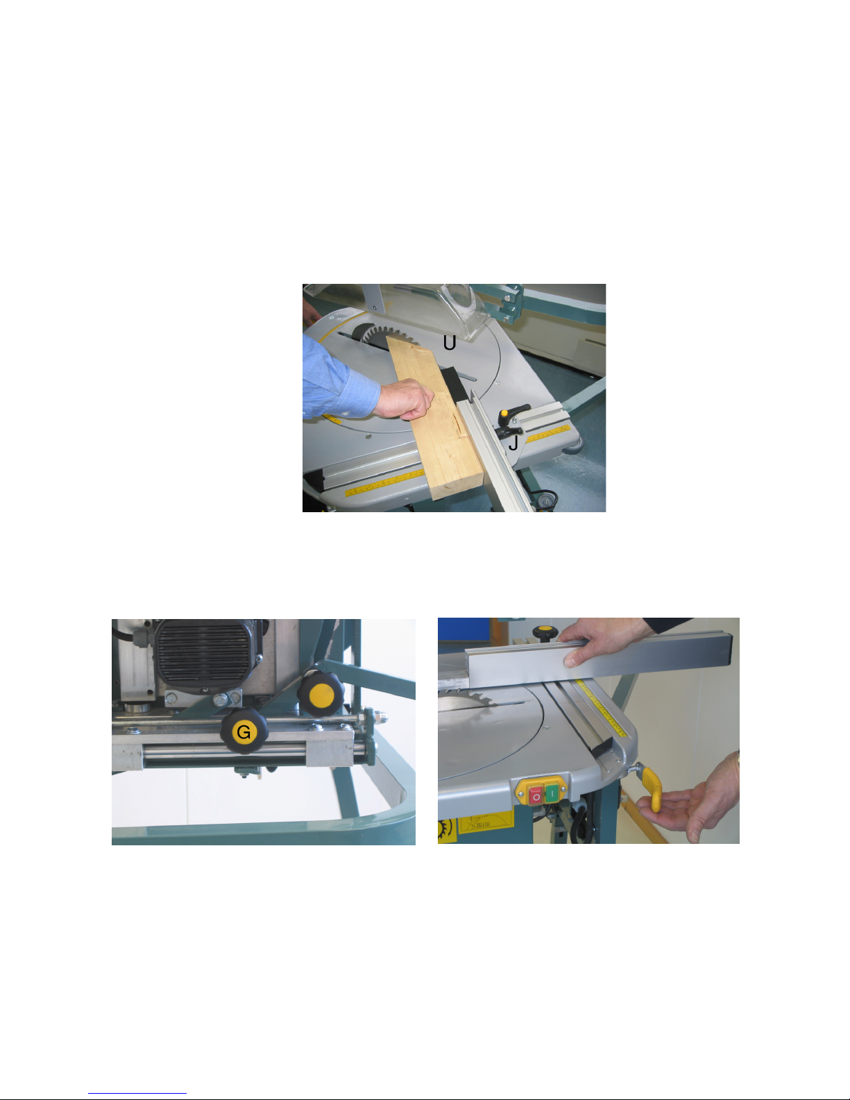
5.1 Cross cutting
* Set the desired cutting angle - Section 4.4. and 4.5.
* Adjust the position of the fence and lock with locking handle JFig. 19.
* Set the upper guard Uapprox. 5 mm above the height of material.
* Lift and (gently) push the blade if you need to increase the cutting width/length.
5.2 Ripping
Turn the blade to the 90° mark so it is parallel to the fence. Lock the turn table as in
Section 4.5 Fig 18. Push the saw blade forward to the end position and lock with wheel G.
Fig. 20.
Tilt the saw blade to the desired angle as in Section 4.4.
Position the blade slightly higher than the thickness of timber you are going to rip, and then
lock in place Fig. 14.
Set the fence for the desired ripping width and lock with the handle Fig. 21.
13
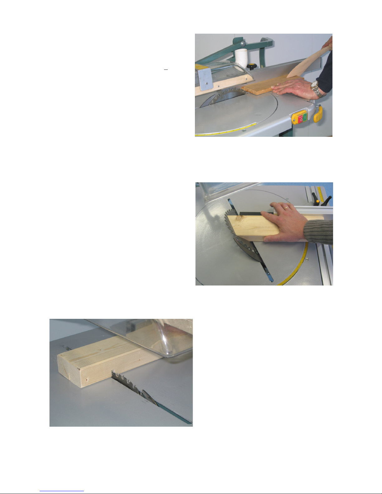
Fig. 22
Start the motor and feed the material
through the blade along the fence Fig. 22.
Use push sticks when the distance
between fence and saw blade is < 120 mm.
NB! The riving knife is always to be
used when ripping. Make sure that
it is correctly tted and adjusted see
Fig. 6, Section 6.2 for settings.
Push gently (reduce the pressure if the motor is working hard) to achieve a clean, neat cut.
5.3 Compound angle cutting
Set the turn table at the desired cutting
angle. Section 4.5.
Tilt the saw blade to the desired angle.
Section 4.4.
Adjust the fence Section 5.2 and
lift the saw blade to complete the
cutting operation Fig. 23.
Fig. 23
Fig. 24
5.4 Cutting grooves
Set the turn table at 0° (square to the
fence) and lock it in position.
Set the saw blade at the desired height
(depth of groove) and adjust the fence
to the correct position.
Place the material against the fence.
Feed material along the fence and
repeat the operation until the grooveis
the desired width Fig. 24.
14
6. MAINTENANCE/REPAIR
CAUTION! MAKE SURE POWER SUPPLY IS DISCONNECTED WHILE PERFORMING
MAINTENANCE OPERATIONS. A minimum of maintenance is required to ensure
satisfactory performance and a long service life.
• Lubricate moving parts at regular intervals.
• Check all screws and nuts regularly for tightness.
• Top guard should be clean. If damaged it should be replaced.
• Keep saw and saw blade cover free from sawdust. Pay particular attention to motor venti-
lation openings and cooling ns.
• Keep saw blade clean and in order. Replace blade if there are any cracks or missing teeth.
Remove resin deposits with a suitable cleaning uid.
• Repairs to electric parts must be carried out by qualied electricians only!
• The motor brushes must be checked evenly and replaced when necessary.
• Do NOT clean the motor with dissolvents.
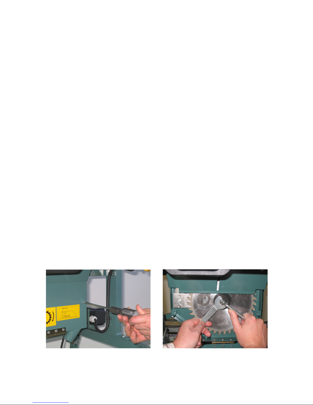
6.1 Replacing saw blade
• Lower the blade and lock it in the forward position.
• Open the cover by loosening the two screws and the nut at the front of the guard Fig. 25.
• Use tools (13 mm spanner) supplied with saw Fig. 26 to remove saw blade. Loosen the
spindle screw whilst blocking the ange with the supplied tool.
Remove outer ange and saw blade. NB! The spindle screw is left-hand thread.
• The saw blade is mounted the opposite way. Be sure to close cover when nished.
The saw is only to be used with saw blades of 250 mm diameter with a bore diameter
of 30 mm, kerf 3,2 mm and a thickness of 2,2 mm. Select a blade with the correct number
of teeth suitable for the work you are performing.
Fig. 25 Fig. 26
15
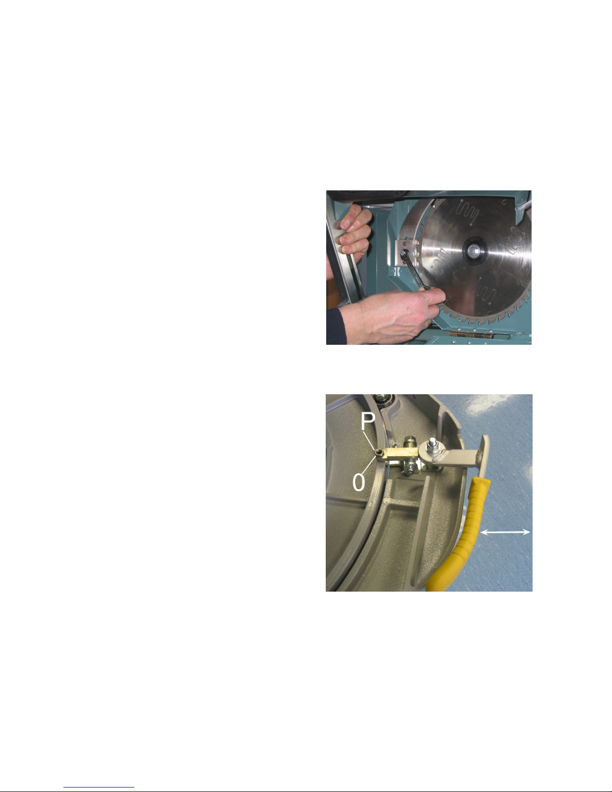
6.2 Replacing and adjusting riving knife
• Pull the plug and lower the blade cover as in Section 6.1.
• Loosen the screws and nut Fig. 27 and remove or reposition the riving knife (by replacing
riving knife).
• The riving knife is mounted using same method in reverse.
The thickness of the riving knife should be the nearest thickness but slightly less than
the kerf width of the saw blade. Adjust the riving knife as shown in Fig. 6 and check that
screws and nut are tight. Be sure to close the saw blade cover when nished.
Fig. 27
6.4 Testing of stop function
The saw blade will stop less than 10 seconds after pushing the red STOP button.
This should be checked regularly.
6.3 Adjusting turn table locking
• Set the locking handle in neutral position.
• Loosen lock nut P.
• Screw the set screw 0 against the turn
table until sufcient locking is achieved
whilst the locking handle is turned to the
locking position.
• Tighten the lock nut PFig. 28.
Fig. 28

16
6.5 Repair
Routines at repair:
* The machine must only be repaired by qualied electricians or authorised service
workshops.
Testing the brakes:
* The brake for the saw blade rotation should be tested regularly. The stop-time
must be max. 10 sec. Start/stop the saw 10 times in a row and check the stop-
time.
7. TROUBLESHOOTING
The saw does not start:
* check the power supply
* do not use the cable with several machines at the same time
* check that the cable is not too long, and that the cross-section is not too small
* contact an electrician
The saw vibrates and is weak:
* check that the blade box under the bench does not contain chips and sawdust
* check that the toothed belt is whole and undamaged
* check the spindle
* check the blade for eccentricity, and that all the teeth are whole and sharp
The saw blade is heavy to lift and does not go down completely:
* check that nothing is stuck in the blade box
* check that the bearings in the universal joint and the movable glide rings at either
end of the spindle are not stuck

17
8. WARRANTY SERVICE
Notwithstanding any statutory requirements, Ernex AS provide warranty in accordance
with the legislation of the customer‘s own country of residence, but in all cases for a mini-
mum of 3 years, except for electrical parts which still has a 1-year warranty commencing
from the date on which the machine is sold to the end user. Ernex AS/The importer prom-
ise to repair, or at our option, replace with like grade and quality any product determined to
be faulty due to the failure of parts, material or workmanship.
The warranty covers defects in material and/or workmanship only. When making a claim
under the warranty, proof of purchase bearing the original date of purchase must be sub-
mitted. The repairs under warranty may only be carried out by Ernex AS, or by authorized
Ernex warranty service agents or the importer.
The warranty will not apply in cases of:
- incorrect use, overloading of the machine or tting non-approved accessories
- use of force, damage caused by external inuences, or foreign bodies
- damage caused by non-observance of the instructions for use, such as connection to an
unsuitable mains supply or voltage or non-compliance with the installation instructions
- normal wear and tear
The warranty also does not cover machines which have been partially or completely dis-
mantled.

18
9. TECHNICAL DATA
Gjerde®250
Manufacturer: Ernex AS, Norway.
Model: Norsaw 250.
Table size: 670 mm x 565 mm.
Height: 860 mm.
Transport height: 430 mm.
Weight: 37 kg.
Saw blade: Carbide tipped, Z=40
Diam. 250 mm.
Bore diam. 30 mm.
Kerf width 3,2 mm.
Riving knife: Hardened steel; std. thickness 2,5 mm.
Cutting height: 80 mm 90° (vertical).
60 mm 45° (tilted)
Slide/push travel: 130 mm
Max. cutting width: 310 mm
Tilt range (stepless): -2° - +47°
Turn table rotation: 0-135° (+ 90° - -45°)
Motor w/Brake: 1.6 kW 110 V/50 Hz 1-phase.
1.8 kW 230 V/50 Hz 1-phase.
Spindle speed: 4.500 rpm.
Peripheral speed: 59 mps.
Cable diam: 1-phase 3 x 2.5 mm2.
Fuse: 16A time-lag.
Switch: On/Off with overload and low-volt cutout
Noise as per 2006/42/EC: No-load 94 dB
Under load 92,4 dB.
-certication: Certied by Dansk Teknologisk
Institut, Aarhus. Identikasjonsnr: ID-No.: 0396
Approval certicate No.: TI-09-MD-0308.
10. STANDARD EQUIPMENT
• Top guard
• Carbide tipped saw blade
• Push sticks
OPTIONAL EQUIPMENT
• Extension table, Aluminium 1m long
• Wheels

19
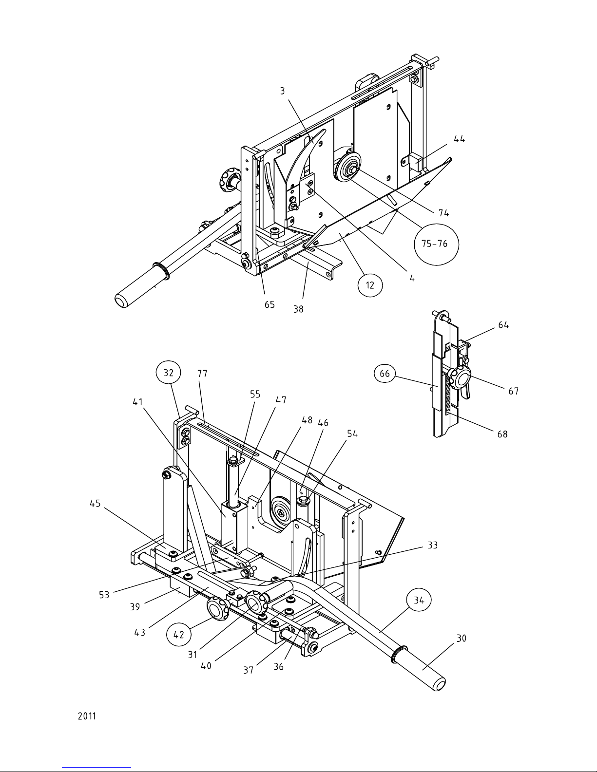
Ernex AS
Spare Part List Gjerde 250
Pos. Art.No. Text
1 725 179 Sawtable top
2 725 178 Turntable w/scale
3 725 019 Riving knife 2.5mm w/clamp
4 725 216 Bracket f/riving knife compl.
5 725 183 Plastic hood w/bracket
6 725 206 Adjusting bar w/handle
7 725 182 Guard arm w/handle
8 725 186 Upper guard compl.
9 725 011 Leg f/frame (1)
10 745 441 Spring stud
11 725 155 Locking handle M8x15
12 725 062 Blade cover compl.
13 725 030 Bottom frame
14 725 207 Foot (set 4) adj.
15 725 208 Rear leg-pair
16 725 209 Locking wheel
17 725 210 Wheel set compl. (2)
18 725 089 Switch 230V/1-phase
19 725 212 Gliding blocks f/alu.profile (3)
20 725 211 Front leg-pair
21 720 075 Plastic sleeve 25x5 (93-99)
22 725 213 Short fence w/extension
23 725 130 Angle fence compl.
24 725 214 Angleplate f/fence
25 725 025 Measure
26 725 027 Plug f/alu.profile (table top)
27 725 121 Alu.profile w/plugs
28 725 024 Tilting scale f/turntable
29 725 151 Extension, plastic
30 720 073 Plastic sleeve Ø22 f/elev.arm (99-)
31 725 101 Locking wheel f/height adj.
32 725 038 Suspension f/axles
33 745 033 Elevation slider
34 725 217 Elevation arm compl.
35 707 019 Hook f/push stick
36 725 043 Locking bar f/push
37 725 023 Tracking axle L=430mm
38 725 144 Angle f/tilting bar
39 725 108 Ballbearing housing, short 50mm
40 725 081 Locking bracket f/lift
41 725 107 Ballbearing housing, long 100mm
42 725 218 Locking device f/push
43 725 109 Bottom plate
44 725 219 End cushion f/push
45 725 077 Bracket f/suspension of lift
46 725 059 Bracket f/blade cover
47 725 022 Tracking axle L=208mm
48 725 110 Plate f/motor suspension
49 725 254 Brushes compl. (2) (1/3-07)
50 760 043 Brushes compl. (2)
51 725 090 Motor 230V/1-phase w/o switch
52 725 092 Motor protection 8Amp
53 725 040 Bracket f/motor lift
54 725 220 End cushion f/elev.
55 725 240 Guide pin
56 725 074 Locking handle f/alu.profile
57 725 073 Locking device f/alu.profile compl.
58 725 020 Carrying handle
59 725 120 Pre-stop plate compl.
60 725 065 Hinge plate compl.
61 725 124 Bracket f/guard arm
62 725 221 Locking f/turntable compl.
63 725 222 Ballbearing set f/turntable (5)
64 725 134 Locking handle f/tilting
65 725 156 Rubber cap
66 725 223 Lock f/tilting compl.
67 725 103 Locking wheel f/tilting
68 725 141 Tilting scale
69 725 224 Switch plate w/hinge
70 725 249 Foot, telescopic
71 725 228 Alu. profile
72 725 241 Plug f/alu. profile
73 725 250 Bearings f/fence
74 760 017 Screw M8x25 lefthanded
75 725 247 Clamps
76 725 255 Clamps (1/3-07)
77 725 236 Rail
78 760 019 Arbor/Gear compl.
79 725 253 Arbor/Gear compl. (03-07-)
80 725 261 Arbor/Gear compl. (10/07-)
81 725 258 Tools f/motor (03/07-)
82 725 245 Start/stop panel
83 725 305 Relay f/switch (725089)
84 725 174 Motor w/switch 230V/1
145 745 099 Push stick
2011
20
Table of contents
Other Ernex AS Saw manuals


