Palmgren 83115 User manual

operating manual & parts list 83115
15″
7 SPEED
METAL/WOOD CUTTING BAND SAW
Read carefully and follow all safety rules and operating instructions before
first use of this product.
35768.00 - 0512

DESCRIPTION
The Palmgren 15” Metal/Wood Cutting Band Saw is for cutting
ferrous and non-ferrous metals and also hard and soft woods. The
band saw features a unitized frame of welded steel construction
and a solid cast iron work surface to ensure durability. Table tilts
45° and has a miter gauge and precision machined rip fence for
performing many different operations. Fifteen inch balanced cast
iron wheels with ball bearings and rubber treads accommodate
blade widths up to 3/4”. A convenient tensioning and tracking mech-
anism makes blade changing quick and easy. Rip fence and miter
gauge can be stored on the saw when not in use.
UNPACKING
Check for shipping damage. If damage has occurred, a claim must
be filed with carrier. Check for completeness. Immediately report
missing parts to dealer.
The band saw comes assembled as one unit. Additional parts
which need to be fastened to the saw should be located and
accounted for before assembling:
A Table Assembly
B Rip Fence with Knob
C Miter auge Assembly
D V-belt
E Metal Cutting Blade, 14 TPI
F Wood Cutting Blade, 6 TPI
Dust Chute
Hardware Bag (Part No. 24958.00) includes:
H Trunnion Rod with Acorn Nut
I Knob with Internal Threads
J Handle
K Front Trunnion
•5/16” Flat Washer (3)
•8-1.25 x 20mm Socket Head Bolt (2)
•8mm Lock Washer (2)
•8/10mm Open End Wrench (1)
•12/14mm Open End Wrench (1)
•2.5, 3mm and 5mm Hex Wrench (1 each)
•5-0.8 x 8mm Pan Head Screw (4)
IMPORTA T: Table is coated with a protectant. To ensure proper
fit and operation, remove coating. Coating is easily removed with
mild solvents, such as mineral spirits, and a soft cloth. Avoid getting
solution on paint or any of the rubber or plastic parts. Solvents
may deteriorate these finishes. Use soap and water on paint, plastic
or rubber components. After cleaning, cover all exposed surfaces
with a light coating of oil. Paste wax is recommended for table top.
WAR I G: Never use highly volatile solvents. Non flammable
solvents are recommended to avoid possible fire hazard.
SPECIFICATIO S
Depth of throat . . . . . . . . . . . . . . . . . . . . . . . . . . . . . . . . . . . . . . . . . . . . . . . 15”
Maximum depth of cut . . . . . . . . . . . . . . . . . . . . . . . . . . . . . . . . . . . . . . . . 10”
Maximum depth of cut @ 45° . . . . . . . . . . . . . . . . . . . . . . . . . . . . . . . . . . . 5”
Table size. . . . . . . . . . . . . . . . . . . . . . . . . . . . . . . . . . . . . . . . . . . . . . . . . 15 x 15”
Table tilt . . . . . . . . . . . . . . . . . . . . . . . . . . . . . . . . . . . . . . . . 10° left - 45° right
Wheel diameter . . . . . . . . . . . . . . . . . . . . . . . . . . . . . . . . . . . . . . . . . . . . . . . 15”
Blade length . . . . . . . . . . . . . . . . . . . . . . . . . . . . . . . . . . . . . . . . . . . . . . . . . 114”
Blade range . . . . . . . . . . . . . . . . . . . . . . . . . . . . . . . . . . . . . . . . . . . . . 112-114”
Blade width . . . . . . . . . . . . . . . . . . . . . . . . . . . . . . . . . . . . . . . . . . . . . . 3/16 to 3/4”
Blade speeds . . . . . . . . . . . . . . . 45, 65, 90, 110, 155, 215 and 3,000 FPM
Overall dimensions (W x D x H) . . . . . . . . . . . . . . . . . . . . . 25 x 27 x 71.5”
Weight . . . . . . . . . . . . . . . . . . . . . . . . . . . . . . . . . . . . . . . . . . . . . . . . . . . . 300 lbs
Crate dimension (W x D x H) . . . . . . . . . . . . . . . . . . . . . . . . . 23 x 23 x 78”
Shipping weight. . . . . . . . . . . . . . . . . . . . . . . . . . . . . . . . . . . . . . . . . . . 346 lbs
Dust collection port . . . . . . . . . . . . . . . . . . . . . . . . . . . . . . . . . . . . . . . . . . . . 4”
SAFETY RULES
WAR I G: For your own safety, read all of the instructions and
precautions before operating tool.
CAUTIO : Always follow proper operating procedures as defined
in this manual — even if you are familiar with use of this or similar
tools. Remember that being careless for even a fraction of a second
can result in severe personal injury.
PROPOSITIO 65 WAR I G: Some dust created by power
sanding, sawing, grinding, drilling and other construction activities
contains chemicals known to the state of California to cause can-
cer, birth defects or other reproductive harm.
Some examples of these chemicals are:
•Lead from lead-based paints.
•Crystalline silica from bricks and cement and other
masonry products.
•Arsenic and chromium from chemically-treated lumber.
Your risk from these exposures vary, depending on how often you
do this type of work. To reduce your exposure to these chemicals:
work in a well ventilated area and work with approved safety
equipment. Always wear OSHA/ IOSH approved, properly fitting
face mask or respirator when using such tools.
Before any work is done, carefully read the cautions listed. Working
safely prevents accidents.
BE PREPARED FOR JOB
•Wear proper apparel. Do not wear loose clothing, gloves, neck-
ties, rings, bracelets or other jewelry which may get caught in
moving parts of machine.
•Wear protective hair covering to contain long hair.
•Wear safety shoes with non-slip soles.
•Wear safety glasses which comply with United States ANSI
Z87.1. Everyday glasses have only impact resistant lenses. They
are NOT safety glasses.
•Wear face mask or dust mask if cutting operation is dusty.
2
Palmgren Operating Manual & Parts List 83115
I
H
K
F
E
D
BC
A
J
Figure 1 - Unpacking

3
SAFETY RULES (CO TI UED)
•Be alert and think clearly. Never operate power tools when
tired, intoxicated or when taking medications that cause
drowsiness.
PREPARE WORK AREA FOR JOB
•Keep work area clean. Cluttered work areas invite accidents.
•Do not use power tools in dangerous environments. Do not use
power tools in damp or wet locations. Do not expose power
tools to rain.
•Work area should be properly lighted.
•Proper electrical outlet should be available for tool.
Three-prong plug should be plugged directly into properly
grounded, three-prong receptacle.
•Extension cords should have a grounding prong, and the three
wires of the extension cord should be of the correct gauge.
•Keep visitors at a safe distance from work area.
•Keep children out of workplace. Make workshop childproof. Use
padlocks, master switches or remove switch keys to prevent
any unintentional use of power tools.
TOOL SHOULD BE MAI TAI ED
•Always unplug tool prior to inspection.
•Consult manual for specific maintaining and adjusting
procedures.
•Keep tool lubricated and clean for safest operation.
•Remove adjusting tools. Form the habit of checking to see that
adjusting tools are removed before switching machine on.
•Keep all parts in working order. Check to determine that the
guard or other parts will operate properly and perform their
intended function.
•Check for damaged parts. Check for alignment of moving parts,
binding, breakage, mounting and any other condition that may
affect a tool’s operation.
•Damaged parts should be properly repaired or replaced. Do not
perform makeshift repairs. (Use the parts list provided to order
replacement parts.)
K OW HOW TO USE TOOL
•Use the right tool for the job. Do not force tool or attachment
to do a job for which it was not designed.
•Disconnect tool when changing blade.
•Avoid accidental start-up. Make sure that the tool is in OFF
position before plugging in.
•Do not force tool. It will work most efficiently at the rate for
which it was designed.
•Keep hands away from moving parts and cutting surfaces.
•Never leave a tool running unattended. Turn the power off and
do not leave tool until it comes to a complete stop.
•Do not overreach. Keep proper footing and balance.
•Never stand on tool. Serious injury could occur if tool is tipped
or if cutter is unintentionally contacted.
•Know your tool. Learn its operation, application and specific
limitations.
•Use recommended accessories (Refer to page 13). Use of
improper accessories may cause risk of injury to persons.
•Handle workpiece correctly. Protect hands from possible injury.
•Turn the machine off if it jams. Blade jams when it digs too
deeply into the workpiece. (The motor force keeps it stuck in
workpiece). Do not remove jammed or cut off pieces until the
saw is turned off, unplugged and the blade has stopped.
WAR I G: The operation of any power tool can result in foreign
objects being thrown into the eyes, which can result in severe eye
damage. Always wear safety goggles complying with United States
ANSI Z87.1 before commencing power tool operation.
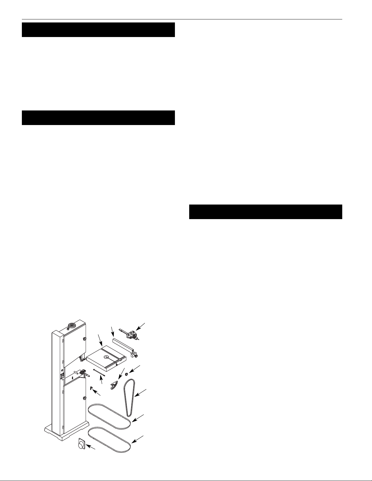
ASSEMBLY
Refer to Figures 2 and 6-11 (pages 4, 7 and 10-18).
CAUTIO : Do not attempt assembly if parts are missing. Use
operator’s manual to order replacement parts.
I STALL METAL CUTTI G BLADE
Refer to Figures 2, 8 and 9.
•Make sure blade teeth are pointing down towards table. Turn
blade inside out if necessary.
•Rotate handwheel (Figure 8, Ref. No. 23) counterclockwise to
move blade wheels towards each other.
•Loosen handle (Figure 9, Ref. No. 30). Rotate handwheel (Figure
9, Ref. No. 22) to lower upper blade guide assembly as low as
possible.
•Loosen three screws (Figure 9, Ref. No. 5). Remove blade guards
(Figure 9, Ref. Nos. 4 and 38).
•Slip blade over upper and lower blade wheels, and center blade
on blade wheels. Slide blade in between blade guides.
•Rotate handwheel clockwise to tension blade.
•Replace blade guards and secure in place by tightening screws.
Raise upper blade guide assembly.
•Position clutch handle (Figure 8, Ref. No. 62) to “Metal”. See
Figure 2.
OTE: The blade must be tensioned and tracked, and the blade
guides must be adjusted before operation of the saw. Refer to
“Tensioning Blade”, “Tracking Blade” and “Blade uides” in the
OPERATION section, page 6.
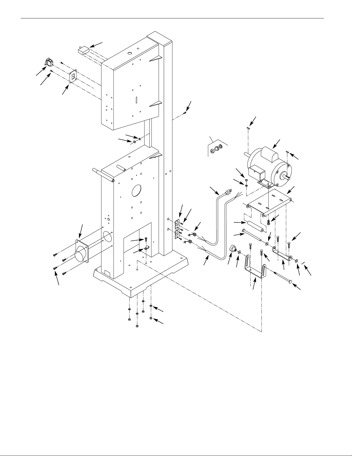
I STALL WOOD CUTTI G BLADE
Refer to figures 2, 7, 8, 9 and 11 (pages 4, 10, 12, 14 and 18).
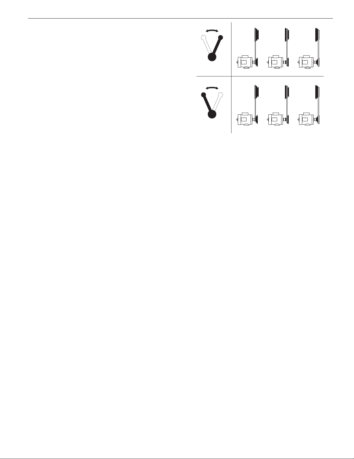
•The V-belt (Figure 11, Ref. No. 44) must be installed first when
using the saw to cut wood.
•Loosen knob (Figure 7, Ref. No. 14). Place V-belt on motor and
drive pulleys (Figure 8, Ref. Nos. 46 and 50).
•Tension V-belt by pushing down on motor mount plate and
tightening knob. Belt is properly tensioned when light pressure
applied to midpoint of the belt produces about 1/2” deflection.
•Make sure blade teeth are pointing down towards table. Turn
blade inside out if necessary.
•Rotate handwheel (Figure 8, Ref. No. 23) counterclockwise to
move blade wheels towards each other.
•Loosen handle (Figure 9, Ref. No. 30). Rotate handwheel (Figure
9, Ref. No. 22) to lower upper blade guide assembly as low as
possible.
•Loosen three screws (Figure 9, Ref. No. 5). Remove blade guards
(Figure 9, Ref. Nos. 4 and 38).
•Slip blade over upper and lower blade wheels, and center blade
on blade wheels. Slide blade in between blade guides.
•Replace blade guards and secure in place by tightening
screws. Raise upper blade guide assembly.
•Rotate handwheel clockwise to tension blade.
•Position clutch handle (Figure 8, Ref. No. 62) to “Wood”. See
Figure 2, page 4.
OTE: The blade must be tensioned and tracked, and the blade
guides must be adjusted before operation of the saw. Refer to
“Tensioning Blade”, “Tracking Blade” and “Blade uides” in the
OPERATION section, page 6.
Palmgren Operating Manual & Parts List 83115

4
ASSEMBLY (CO TI UED)
ATTACH DUST CHUTE
Refer to Figure 7, page 10.
•Position dust chute (Ref. No. 29) against saw frame. Secure in
position using four pan head screws (Ref. No. 3).
ATTACH TABLE
Refer to Figure 10, page 16.
•Table (Ref. No. 1) is attached to frame with two cast iron trunnions.
•Remove table stud (Ref. No. 16).
•Finger tighten one socket head bolt with washer (Ref. Nos. 3
and 4) on left side of front trunnion (Ref. No. 2) into table.
•Bring table to frame by inserting back of blade into slot.
Position table with back trunnion (Ref. No. 5) on guide posts
which are welded to frame.
•Position front trunnion so it rides on guide post. Attach handle
with flat washer (Ref. Nos. 13 and 11) to secure back trunnion.
•Insert trunnion rod with acorn nut and flat washer (Ref. Nos. 10
and 11) through other guide post and attach the internally
threaded knob with flat washer (Ref. Nos. 12 and 11) to the
trunnion rod.
•Mount second bolt with washer on front trunnion. Position
front trunnion flat against bottom of table and tighten internal-
ly threaded knob to secure.
•Tighten socket head bolts (Ref. No. 3) to secure trunnions to
table. Install table stud.
SET HORIZO TAL STOP
Refer to Figure 10, page 16.
•When table is attached to frame, a bolt (Ref. No. 14) is used for a
horizontal stop.
•Loosen trunnion knob and set table at 90° to blade using a
square.
•Secure position of table with knob.
•Adjust bolt to contact bottom edge of table.
•Lock bolt in position with hex nut (Ref. No. 15).
ATTACH RIP FE CE
Refer to Figure 10, page 16.
•Rip fence (Ref. No. 19) rides in the slot of table (Ref. No. 1).
•Slide rip fence into slot.
•Hold rip fence to table and fasten by threading knob
(Ref. No. 20) into rip fence.
•Rip fence can be repositioned by loosening knob.
ALIG TABLE
Refer to Figure 10, page 16.
•The table must be aligned properly so that the blade is at a
right angle to the table and that the rip fence is aligned with
the blade.
•Lock the table in the horizontal position. Mount the rip fence
on the table. Slide the rip fence next to, but not touching, the
blade. Lock the rip fence.
•Check that the blade is aligned parallel with the rip fence. If the
blade and fence are not parallel, loosen handle and knob (Ref.
Nos. 12 and 13) on the trunnions (Ref. Nos. 2 and 5). Adjust the
table position so that the blade and rip fence are parallel.
Secure the table position by tightening handle and knob.
•After assembly, the table has to be aligned in order to have the
blade running through the center of the slot in the table insert.
•To move table sideways, loosen bolts (Ref. No. 3) on the trun-
nions (Ref. Nos. 2 and 5). Move table to left or right until blade
runs through the center of slot. Tighten bolts and make sure
that table stays in position while bolts are being tightened.
I STALL V-BELT (METAL CUTTI G)
Refer to Figures 6, 7 and 11 (pages 7, 10 and 18).
•Band saw uses a step-pulley drive system to provide a selection
of blade speeds for metal cutting.
•Loosen knob (Figure 7, Ref. No. 14). Place V-belt (Figure 11, Ref.
No. 44) on idler pulley and motor pulley (Figure 11, Ref. Nos. 38
and 40) with V-belt in desired location on pulleys. (See Figure 6,
Blade Speeds, page 7.)
•Do not over tighten V-belts. Excessive tension on V-belt will
reduce life of belt. Belt is properly tensioned when light
pressure applied to midpoint of the belt produces about
1/2” deflection.
•Tension V-belt by pushing down on motor mount plate and
tightening hex head bolt and hex nut.
MOU T SAW TO FLOOR
•If saw is not properly positioned on a flat surface, it may
develop excessive vibration.
•Mount to a flat, level surface through holes on top of base.
INSTALLATION
Refer to Figures 3, 4 and 5, page 5.
MOTOR
The 115/230 Volt AC motor has the following specifications:
Horsepower. . . . . . . . . . . . . . . . . . . . . . . . . . . . . . . . . . . . . . . . . . . . . . . . . . . . . 1
Voltage . . . . . . . . . . . . . . . . . . . . . . . . . . . . . . . . . . . . . . . . . . . . . . . . . . 115/230
Amps . . . . . . . . . . . . . . . . . . . . . . . . . . . . . . . . . . . . . . . . . . . . . . . . . . . . . . . . 14/7
Hertz . . . . . . . . . . . . . . . . . . . . . . . . . . . . . . . . . . . . . . . . . . . . . . . . . . . . . . . . . . 60
Phase . . . . . . . . . . . . . . . . . . . . . . . . . . . . . . . . . . . . . . . . . . . . . . . . . . . . . . Single
RPM. . . . . . . . . . . . . . . . . . . . . . . . . . . . . . . . . . . . . . . . . . . . . . . . . . . . . . . . . 1725
POWER SOURCE
The motor is designed for operation on the voltage and frequency
specified. Normal loads will be handled safely on voltages not more
than 10% above or below the specified voltage.
Running the unit on voltages which are not within the range may
cause overheating and motor burn-out. Heavy loads require that
the voltage at motor terminals be no less than the voltage speci-
fied. Power supply to the motor is controlled by a double pole
locking rocker switch. Remove the key to prevent unauthorized
use.
GROU DI G I STRUCTIO S
WAR I G: Improper connection of equipment grounding con-
ductor can result in the risk of electrical shock. Equipment should
be grounded while in use to protect operator from electrical
shock.
Palmgren Operating Manual & Parts List 83115
Figure 2 - Clutch Handle Position
Wood
Metal

5
Palmgren Operating Manual & Parts List 83115
I STALLATIO (CO TI UED)
Check with a qualified electrician if grounding instructions are not
understood or if in doubt as to whether the tool is properly
grounded.
This tool is equipped with an approved 3 conductor cord rated at
300V and a three prong grounding type plug for your protection
against shock hazards.
rounding plug should be plugged directly into a properly
installed and grounded 3- prong grounding-type receptacle, as
shown (Figure 3).
Do not remove or alter grounding prong in any manner. In the
event of a malfunction or breakdown, grounding provides a path
of least resistance for electrical shock.
WAR I G: Do not permit fingers to touch the terminals of plug
when installing or removing from outlet.
Plug must be plugged into matching outlet that is properly
installed and grounded in accordance with all local codes and
ordinances. Do not modify plug provided. If it will not fit in outlet,
have proper outlet installed by a qualified electrician.
Inspect tool cords periodically, and if damaged, have them repaired
by an authorized service facility.
reen (or green and yellow) conductor in cord is the grounding
wire. If repair or replacement of the electric cord or plug is neces-
sary, do not connect the green (or green and yellow) wire to a live
terminal.
Where a 2-prong wall receptacle is encountered, it must be
replaced with a properly grounded 3-prong receptacle installed in
accordance with National Electric Code and local codes and
ordinances.
WAR I G: This work should be performed by a qualified
electrician.
A temporary 3-prong to 2-prong grounding adapter (see Figure 4)
is available for connecting plugs to a two pole outlet if it is
properly grounded.
Do not use a 3-prong to 2-prong grounding adapter unless permit-
ted by local and national codes and ordinances. (A 3-prong to 2-
prong grounding adapter is not permitted in Canada.) Where per-
mitted, the rigid green tab or terminal on the side of the adapter
must be securely connected to a permanent electrical ground such
as a properly grounded water pipe, a properly grounded outlet
box or a properly grounded wire system.
Many cover plate screws, water pipes and outlet boxes are not
properly grounded. To ensure proper ground, grounding means
must be tested by a qualified electrician.
ELECTRICAL CO ECTIO S
WAR I G: All electrical connections must be performed by a
qualified electrician. Make sure unit is off and disconnected from
power source while motor is mounted, connected, reconnected or
anytime wiring is inspected.
•Band saw motor can be wired for 115 or 230 volts, single-phase
operations.
•See wiring diagram (Figure 5) for wiring instructions.
EXTE SIO CORDS
•The use of any extension cord will cause some drop in voltage
and loss of power.
•Wires of the extension cord must be of sufficient size to carry
the current and maintain adequate voltage.
•Use the table to determine the minimum wire size (A.W. .)
extension cord.
•Use only 3-wire extension cords having 3-prong grounding
type plugs and 3-pole receptacles which accept the tool plug.
•If the extension cord is worn, cut or damaged in any way,
replace it immediately.
EXTE SIO CORD LE GTH (120 VOLTS)
Wire Size A.W.G.
Up to 25 ft.. . . . . . . . . . . . . . . . . . . . . . . . . . . . . . . . . . . . . . . . . . . . . . . . . . . . . 14
25-50 ft. . . . . . . . . . . . . . . . . . . . . . . . . . . . . . . . . . . . . . . . . . . . . . . . . . . . . . . . 12
OTE: Using extension cords over 50 ft. long is not recommended.
EXTE SIO CORD LE GTH (240 VOLTS)
Wire Size A.W.G.
Up to 50 ft.. . . . . . . . . . . . . . . . . . . . . . . . . . . . . . . . . . . . . . . . . . . . . . . . . . . . . 18
50-100 ft. . . . . . . . . . . . . . . . . . . . . . . . . . . . . . . . . . . . . . . . . . . . . . . . . . . . . . . 16
100-200 ft. . . . . . . . . . . . . . . . . . . . . . . . . . . . . . . . . . . . . . . . . . . . . . . . . . . . . . 14
200-300 ft. . . . . . . . . . . . . . . . . . . . . . . . . . . . . . . . . . . . . . . . . . . . . . . . . . . . . . 12
OTE: Using extension cords over 300 ft. long is not recommended.
Figure 5 - Wiring Diagram
Switch
Motor
L1
L1
L2
L2
Red
Red
#6
#6
#5
Circuit
Breaker
Yellow Black White
White #5Black Yellow
115 V
230 V
Figure 3 – 3-Prong Receptacle
Properly rounded Outlet
rounding Prong
3-Prong Plug
Figure 4 – 2-Prong Receptacle with adapter
rounding Lug
Adapter
3-Prong Plug
2-Prong Receptacle
Make sure this is
Connected to a known
rounded Receptacle

6
Palmgren Operating Manual & Parts List 83115
OPERATION
CAUTIO : Always observe the following safety precautions:
•Make sure that blade guides and thrust bearings are positioned
and adjusted correctly to prevent sideways and rearward
movement of the blade. Adjust upper guide to just clear work-
piece.
•Check to make sure blade is tensioned and tracking properly.
Do not over tension the blade in order to prevent premature
blade wear and breakage. Avoid under tensioning to eliminate
back and forth, side to side blade movement as it cuts.
•Use proper blade and speed for the cutting operation.
•After turning saw on, allow blade to come to full speed before
attempting any cutting operation.
•Support workpiece properly and use a smooth steady feed to
guide work through the cut. Use push sticks or push blocks
when required.
•Keep hands away and out of line with moving parts.
•Always wear eye protection.
REMOVI G BLADE
Refer to Figures 8, 9 and 10 (pages 12, 14 and 16).
WAR I G: Disconnect band saw from power source when
changing or adjusting blades. Wear leather gloves when handling
band saw blades. Never wear gloves when operating saw.
•Loosen three screws (Figure 9, Ref. No. 5). Remove blade guards
(Figure 9, Ref. Nos. 4 and 38). Loosen handle (Figure 8, Ref. No.
30) and rotate handwheel (Figure 8, Ref. No. 23) to release blade
tension. Be careful; blade may spring from saw when tension is
released. Remove table stud (Figure 10, Ref. No. 16), take out the
released blade and replace with another blade.
I STALLI G BLADE
•Although many of the adjustments may not be altered when
blade is removed, every adjustment should be checked prior to
using a newly installed blade.
•Follow safety precautions every time saw is operated.
•Make sure blade teeth are pointing down towards table. Turn
blade inside out if necessary.
•Slip new blade into table slot and over upper and lower blade
wheels and center blade on blade wheels. Slide blade in
between blade guides. Replace table stud. Replace blade
guards after blade guide adjustment.
•Tension and track blade as described in the following sections.
TE SIO I G BLADE
Refer to Figure 8, page 12.
•Tension blade by rotating handwheel (Ref. No. 23). Be sure
blade guides do not interfere with blade path.
•Tighten blade until it is properly tensioned.
•A properly tensioned blade will ring slightly when back of
blade is plucked (like a string on an instrument).
OTE: Check tension of new blade. Additional tension may be
required after a few minutes of operation.
TRACKI G BLADE
Refer to Figure 8, page 12.
•Track blade after it has been tensioned. A change in blade ten-
sion will affect wheel alignment.
•Proper tracking is achieved when drive and idler wheels are
aligned. Knob (Ref. No. 29) is used to tilt tracking bar (Ref. No.
13) and align blade wheels.
•Loosen hex nuts (Ref. No. 30) which lock tracking knob (Ref. No.
29). Turn idler wheel (Ref. No. 7) by hand and observe how
blade rides on wheels.
•If blade rides away from cabinet, turn knob clockwise to tilt
idler wheel up.
•If blade rides into cabinet, turn tracking knob counterclockwise.
•When blade is tracking properly, lock position by holding knob
and tightening hex nuts (Ref. No. 30) against the cabinet.
ALIG ME T OF DRIVE WHEEL
Refer to Figure 11, page 18.
OTE: Only attempt adjusting drive wheel alignment if blade
cannot be properly tracked with tracking adjustment alone.
•A blade under high tension may also pull drive wheel out of
alignment.
•Adjust alignment of drive wheel using hex head bolts (Ref. No. 9).
BLADE GUIDES
OTE: Adjust blade guides only after blade has been properly
tensioned and tracked.
•Blade guides support blade at sides and rear of blade, and
prevent twisting or deflection.
•Blade guides should not touch blade when no workpiece is in
contact with blade. Adjust guides as described in following
sections.
UPPER BLADE GUIDES
Refer to Figure 9, page 14.
•Upper blade guides employ guide pins for side support and a
ball bearing on an adjusting pin at rear.
•Upper guide bracket (Ref. No. 13) should be positioned so
guide on either side of blade will support as much of blade
width as possible without interfering with the tooth set.
•Adjust bracket depth by loosening bolts (Ref. Nos. 9 and 12)
and sliding brackets into position. Secure position of upper
guide casting by tightening bolts.
•Loosen set screws (Ref. No. 15) and adjust guide pins (Ref. No.
14) to side of blade. Use a feeler gauge to check that guide pins
are .002” away from blade.
•Lock adjustment by tightening set screws.
•Adjust thrust bearing (Ref. No. 17) at rear of blade by loosening
set screw (Ref. No. 15).
•Position thrust bearing .002” away from back of blade.
•Secure position of thrust bearing by tightening set screw.
•Adjust the height of upper guide casting to clear the workpiece
by 1/4”. Loosen knob (Ref. No. 30) and rotate height adjustment
knob (Ref. No. 22) until upper blade guide bracket clears work-
piece by 1/4”. Tighten knob.
LOWER BLADE GUIDES
Refer to Figure 9, page 14.
•Lower blade guides employ two guide blocks for side support.
Lower guide bracket is spaced close to table surface to mini-
mize unsupported length of blade.
•Loosen screw (Ref. No. 5) and remove blade guard (Ref. No. 38).
•Loosen bolt (Ref. No. 19) to position lower guide bracket on
alignment block (Ref. No. 31). Adjust lower guide bracket so
guide blocks do not interfere with blade set. Loosen set screws
(Ref. No. 23) for guide blocks (Ref. Nos. 21 and 34) and adjust
guide blocks to .002” from each side of blade.

7
Palmgren Operating Manual & Parts List 83115
OPERATIO (CO TI UED)
•Adjust thrust bearing (Ref. No. 36) at rear of blade by loosening
set screw (Ref. No. 23). Position thrust bearing .002” away from
back of blade. Secure position of thrust bearing by tightening
set screw.
•Replace blade guard and secure in position.
BLADE SELECTIO
•Blades vary depending on type of material, size of workpiece
and type of cut that is being performed.
•Characteristics which make blades different are width, thick-
ness and pitch.
BLADE WIDTH
•Width of blade describes distance from tip of a tooth to back of
blade.
•Width of blade will affect rigidity of blade. A wider blade will
wander less and produce a straighter cut.
•Width of blade also limits the smallest radius which can be cut.
A 1/4” wide blade can cut about a 1/2” radius.
BLADE THICK ESS
•Blade thickness describes the distance between sides of blade.
A thicker blade has more rigidity and stronger teeth.
•A narrow thick blade would be used to cut curves while a wide
thin blade would be used to make long, straight cuts.
BLADE PITCH
•Pitch describes number of teeth per inch or tooth size. A blade
with more teeth per inch will produce a smoother cut.
•The type of material being cut determines number of teeth
which should be in contact with work.
•For soft metals, the proper blade has between 6 to 12 teeth per
inch.
•When cutting hard metals, where shocking is more detrimental,
use a blade with 12 to 24 teeth per inch.
•For softwoods, the proper blade has 4 to 8 teeth per inch.
•For hardwoods, the proper blade has 8 to 12 teeth per inch.
•There should always be at least three teeth in contact with cut
to avoid shocking blade.
•Blade shocking occurs when pitch is too large and blade tooth
encounters too much material. This can strip teeth from blade.
•Blade manufacturers are prepared to supply information about
blades for specific applications.
BLADE SPEED
Refer to Figure 6.
•The amount of force with which the blade cuts is determined
by speed.
•High cutting speeds are used on soft materials where less force
is needed and a high rate of material removal is desired.
•Low cutting speeds are used on hard materials when more
force is required.
•To change blade speed, position V-belt in proper configuration
(see Figure 6). Reposition and tension V-belt as described in the
next section.
45 FPM. . . . . . . . . . . . . . . . . . . . . . . . . . . . . . . . . . . . . . . . . . . . . Stainless Steel
65 FPM . . . . . . . . . . . . . . . . . . . . . . . . . . . . . . . . . . . . . . . . . . . . . . . . . . Cast Iron
90 FPM. . . . . . . . . . . . . . . . . . . . . . . . . . . . . . . . . . . . . . Tool Steel, Alloy Steel
110 FPM . . . . . . . . . . . . . . . . . . . . . . . . . . . . . . . . . . . . . . . Hard Brass, Bronze
155 FPM. . . . . . . . . . . . . . . . . . . . . . . . . . . . . . . . . . . . . . . . Soft Brass, Copper
215 FPM . . . . . . . . . . . . . . . . . . . . . . . . . . . . . . . . . . . . . . . . . . . . . . . Aluminum
REPOSITIO I G V-BELT (METAL CUTTI G)
Refer to Figures 6, 7 and 11(pages 7, 10 and 18).
•Blade speed is determined by the position of the V-belt on the
idler and motor pulleys (Figure 11, Ref. Nos. 38 and 40). Blade
speed is changed by changing pulley position of V-belt.
•Be sure to disconnect saw from power and turn saw OFF before
attempting to change blade speed.
•To change blade speed loosen motor mount plate (Figure 7,
Ref. No. 9) by loosening knob (Figure 7, Ref. No. 14). Position V-
belt on motor and idler pulleys as required. See Figure 6, Blade
Speeds, for recommended pulley and belt settings.
•Tension V-belt by pushing down on motor mount plate and
tightening knob. Belt is properly tensioned when light pressure
applied to midpoint of the belt produces about 1/2” deflection.
Do not over tighten V-belt.
CHA GI G THE SAW OPERATIO FROM METAL TO
WOOD CUTTI G
Refer to Figures 2, 7, 8 and 11 (pages 4, 10, 12 and 18).
•Remove metal cutting blade. See “Removing Blade”, page 6.
•Remove shroud (Figure 11, Ref. No. 48).
•Loosen knob (Figure 7, Ref. No. 14). Remove V-belt from motor
and idler pulleys (Figure 11, Ref. Nos. 38 and 40).
•Place V-belt on motor and drive pulleys (Figure 8, Ref. Nos. 46
and 50).
•Tension V-belt by pushing down on motor mount plate and
tightening knob. Belt is properly tensioned when light pressure
applied to midpoint of the belt produces about 1/2” deflection.
•Change clutch handle from “metal” to “wood”. (Refer to Figure 2,
page 4).
•Replace shroud.
•Install wood cutting blade. See “Installing Blade”, page 6.
Properly tension, track and adjust blade guides before
operation.
CHA GI G THE SAW OPERATIO FROM WOOD TO
METAL CUTTI G
Refer to Figures 2, 7, 8 and 11 (pages 4, 10, 12 and 18).
•Remove wood cutting blade. See “Removing Blade”, page 6.
•Loosen knob (Figure 7, Ref. No. 14). Remove V-belt from motor
and drive pulleys (Figure 8, Ref. Nos. 46 and 50).
•Remove shroud (Figure 11, Ref. No. 48).
L H
High Range
LH
Low Range
110 FPM 155 FPM 215 FPM
45 FPM 65 FPM 90 FPM
Figure 6 - Blade Speeds

8
Palmgren Operating Manual & Parts List 83115
OPERATIO (CO TI UED)
•Place V-belt on motor and idler pulleys (Figure 11, Ref. Nos. 38
and 40).
•Tension V-belt by pushing down on motor mount plate and
tightening knob. Belt is properly tensioned when light pressure
applied to midpoint of the belt produces about 1/2” deflection.
•Change clutch handle from “wood” to “metal”. (Refer to Figure 2,
page 4).
•Replace shroud.
•Install metal cutting blade. See “Installing Blade”, page 6. Properly
tension, track and adjust blade guides before operation.
TYPE OF CUT
•Rip fence guides workpiece to produce straight cuts on longer
pieces.
•Contour cutting is done by guiding workpiece free-handed to
produce curved shapes.
•Beveled cutting can be done by tilting table and using proper
work guide method.
•Regardless of which work guiding method is used, a workpiece
which overhangs table by more than 7” should be properly
supported by support stands. (See Recommended Accessories,
page 13.)
RIP FE CE OPERATIO
Refer to Figures 10 and 11 (pages 16 and 18).
•Rip fence can be used to guide boards with one square edge
past blade when table is aligned properly.
•Set rip fence to desired width of cut on inside of throat.
Remember to include the thickness of material that will be
removed by blade.
•Use a square to measure from tip of a tooth to fence. Lock
fence securely with knob (Fig 10, Ref. No. 20).
•The portion of material between blade and fence is considered
the workpiece. Material on outside and behind cut is the scrap
material which is being cut off. Use the right hand to keep work
against fence.
•Do not push on scrap portion of the work. This could pinch or
bind blade.
•Avoid passing hands beyond the cut. Use push sticks or push
blocks to finish cuts and pass workpiece away from blade.
•A storage bracket (Fig. 11, Ref. No. 21) for rip fence is located on
the rear of saw.
CO TOUR SAWI G
•When contour sawing, use both hands to keep work-piece flat
against table and guided along desired path.
•Avoid positioning hands in line with blade. If hands slip they
could contact blade.
•Try to stand to front of the saw and use hands over the portion
of table which is to right of blade and before cut.
•Cut small corners by sawing around them. Saw to remove scrap
until desired shape is obtained.
BEVEL CUTTI G
Refer to Figure 10, page 16.
•Perform a bevel operation by tilting table. Loosen handle and
knob (Ref. Nos. 12 and 13) and tilt table to desired position.
•Use a square or protractor to set angle and lock table in posi-
tion with knob. Use caution when supporting work while bevel
cutting. Do not allow work to hang on blade.
MITER GAUGE
Refer to Figure 10, page 16.
•Use miter gauge for securing and holding workpiece at desired
angle to produce angled cuts. Use scale to adjust gauge to
desired angle.
•Never use miter gauge and rip fence at the same time. The
blade might bind in the workpiece. Operator could be injured
and/or workpiece could be damaged.
•A storage bracket (Ref. No. 39) for miter gauge is located on the
rear of saw.
BLADE CLEA I G BRUSH
Refer to Figure 8, page 12.
•Make sure that brush (Ref. No. 36) is in contact with blade to
properly remove foreign particles from drive wheel.
CHIP BLOWER
Refer to Figure 11, page 18.
Band saw is equipped with chip blower used to remove chips to
make contour cutting easier.
Adjust air nozzle (Ref. No. 45) so that pump air blows chips away
from blade and workpiece.
MAINTENANCE
WAR I G: Make certain that unit is disconnected from power
source before attempting to service or remove any component.
CLEA I G
•Keep machine and workshop clean. Do not allow sawdust to
accumulate on band saw.
•Keep wheels clean. Debris on wheels will cause poor tracking
and blade slippage.
•Keep mechanisms and threaded or sliding surfaces clean and
free of foreign particles.
•Operate band saw with a dust collector to minimize clean up.
LUBRICATIO
•The shielded ball bearings are permanently lubricated and
require no further lubrication.
•Small amounts of machine oil can be applied to belt tension
mechanisms and threaded or sliding surfaces.
•Occasionally apply a coat of paste wax to table top to keep it
slick and corrosion free.
KEEP BA D SAW I REPAIR
•If power cord is worn or cut in any way, have it replaced.
•Replace V-belt and blade when they are worn. Replace any
damaged or missing part.
•Use parts list to order parts.

Palmgren Operating Manual & Parts List 83115
9
TROUBLESHOOTING
SYMPTOM
Excessive blade breakage
Premature blade dulling
Crooked cuts
Rough cuts
Blade is twisting or unusual wear on
side/back of blade
Teeth ripping from blade
Motor running too hot
Saw will not start
POSSIBLE CAUSES
1. Material not secure on table
2. Incorrect speed or feed
3. Blade too coarse for material
4. Incorrect blade tension
5. Teeth in contact with work before
sawing
6. Blade rubs on wheel flange
7. Misaligned guides
8. Blade too thick for wheel diameter
9. Cracking at weld
1. Blade too coarse
2. Excessive blade speed
3. Inadequate feed pressure
4. Hard spots or scale in or on
material
5. Work hardening of workpiece
6. Blade installed backwards
7. Insufficient blade tension
1. Work not square
2. Rate of feed too great
3. Blade guides not adjusted properly
4. Insufficient blade tension
5. Upper blade guide too far
from workpiece
6. Dull blade
7. Incorrect speed
8. Blade guide assembly loose or
blade thrust bearing loose
1. Too much speed or feed
2. Blade too coarse
1. Cut is binding blade
2. Blade guides or bearing worn
3. Blade guides or bearings not
adjusted properly
4. Blade guide brackets loose
1. Teeth too coarse for work
2. Rate of feed too great
3. Vibrating workpiece
4. Teeth filling with material
1. Blade tension too great
2. Blade too coarse for work
(typical when cutting pipe)
3. Blade too fine for work (typical
when cutting slick or soft material)
4. Excessive dirt and chips
Loose electrical connections
CORRECTIVE ACTIO
1. Squarely place work on table
2. Check Blade Speed (Figure 6, page 7)
3. Use finer pitch blade
4. Tension blade properly; see “Operation”
5. Place blade in contact with work after saw
is started and has reached full speed
6. Adjust wheel alignment properly
7. Adjust blade guides properly
8. Use thinner blade
9. Replace blade
1. Use finer tooth blade
2. Try lower speed
3. ently increase pressure
4. Reduce speed; increase rate of feed for
scale and change blades for hard spots
5. Increase rate of feed
6. Remove blade, twist inside out and
reinstall blade
7. Tension blade properly; see “Operation”
1. Use rip fence; adjust tilt of table at 90°
to blade
2. Reduce rate of feed
3. Move both guide blocks within .002”from
blade (use gauge)
4. Tension blade properly; see “Operation”
5. Adjust upper guide to just clear workpiece
by 1/4”
6. Replace blade
7. Check Blade Speed; see Figure 6, page 7 for
recommended speeds
8. Tighten blade thrust bearing within .002”
behind blade back
1. Reduce speed or feed
2. Replace with finer blade
1. Decrease feed pressure
2. Replace
3. Adjust blade guides; see “Operation”
4. Tighten properly
1. Use blade with finer teeth
2. Decrease feed rate
3. Hold workpiece firmly
4. Use blade with coarser teeth
1. Reduce tension on blade
2. Use blade with finer teeth
3. Use blade with coarser teeth
4. Clean thoroughly; vacuum motor and
speed change mechanism
Have qualified electrician check
electrical connections

10
Palmgren Operating Manual & Parts List 83115
Figure 7 - Replacement Parts Illustration for Motor
6
25
20
8
7
28
22
21
23
9
18
18
11
12
14
15
17
12
21
22
3
2
1
10
4
5
13
19
16
12
26
27
29
3
3
3
24
23

11
Palmgren Operating Manual & Parts List 83115
Ref.
o. Description Part umber Qty.
1 Switch 16080.00 1
2 Switch Plate 03668.00 1
3 5-0.8 x 8mm Pan Head Screw 00361.00 13
4 4mm Serrated Washer *1
5 4-0.7mm Hex Nut *1
6 Line Cord 18970.00 1
7 Motor Cord 18971.00 1
8 Strain Relief 02434.00 2
9 Motor Mount Plate 08294.00 1
10 Slide Bracket 08295.00 1
11 3/8-16 x 61/2” Carriage Bolt 18924.00 1
12 3/8” Flat Washer *3
13 Spacer 08297.00 1
14 Knob 18953.00 1
15 Pivot Bracket 08299.00 1
16 Clevis Pin 08300.00 1
17 1/8x 1” Cotter Pin 00665.00 1
18 8-1.25 x 20mm Hex Head Bolt *4
19 8-1.25 x 20mm Carriage Bolt 05188.00 4
20 Strain Relief 01634.00 1
21 8mm Lock Washer *8
22 8-1.25mm Hex Nut *8
23 3/16 x 3/16 x 11/2” Key 02813.00 2
24 Motor 18972.00 1
25 4-0.7 x 15mm Pan Head Screw 08685.00 1
26 Strain Relief Plate 08677.00 2
27 Cord Clamp 03981.00 1
28 Circuit Breaker 04287.00 1
29 Dust Chute 24934.00 1
∆Capacitor 22807.00 1
REPLACEMENT PARTS LIST FOR MOTOR
* Standard hardware item available locally.
∆Not shown.

12
Palmgren Operating Manual & Parts List 83115
Figure 8 – Replacement Parts Illustration for Front
18
19
6
5
4
3
6
6
5
4
7
9
9
2
8
6
8
24
26
26
26
31
30
57
10
10
25
25
26
36
27
27
34
43
44
45
45
49
50
51, 52
47
48
53
54
56
58
62
42
63
59
60
61
55
46
38
15
15
15
15
15
33
40
32
1
41
6
29
35
35
28
23
16
17
21
21
21
20
20
20
22
12
11
13 14
37
39

13
Palmgren Operating Manual & Parts List 83115
* Standard hardware item available locally.
REF.
O. DESCRIPTIO PART O. QTY.
1 Frame N/A 1
2 Upper Cabinet Door 24959.00 1
3 Lower Cabinet Door 08303.09 1
4 Knob (External Threads) 03663.00 2
5 Latch 08304.00 2
6 6-1.0 x 6mm Set Screw 00964.00 9
7 Idler Wheel 24960.00 1
8 Rubber Tread 08306.00 2
9 3BMI-40 Retaining Ring 03838.00 2
10 6203ZZ Bearing 01901.00 2
11 Idler Shaft 06358.01 1
12 3AMI-17 Retaining Ring 00341.00 1
13 Tracking Bar 03605.01 1
14 8-1.25 x 25mm Hex Head Bolt *1
15 8mm Lock Washer * 12
16 Tracking Adjustment Bracket 03608.00 1
17 Tension Bracket 03606.00 1
18 Upper Cabinet Support 03609.00 2
19 8-1.25 x 70mm Hex Head Bolt *2
20 8mm Flat Washer *8
21 8-1.25mm Hex Nut *9
22 Threaded Shaft 08601.00 1
23 Handwheel 05598.01 1
24 Tension Support 03610.00 1
25 6-1.0 x 16mm Hex Head Bolt *8
26 6mm Flat Washer * 16
27 6-1.0mm Hex Nut *8
28 Tension Nut 03607.00 1
29 Tracking Knob 08307.00 1
30 5/16”-18 Hex Nut *2
31 10-1.5mm Eye Bolt 08308.00 1
32 10mm Flat Washer *1
REF.
O. DESCRIPTIO PART O. QTY.
33 10-1.5mm Hex Nut *1
34 Drive Wheel 24961.00 1
35 3BMI-42 Retaining Ring 07904.00 2
36 Brush 20071.00 1
37 Bracket 03620.00 1
38 4.8-2.1 x 8mm Thread Forming Screw 17741.00 2
39 5-0.8 x 15mm Pan Head Screw 01090.00 1
40 5mm Flat Washer *2
41 17mm Wavy Washer 08439.00 1
42 8-1.25 x 8mm Set Screw 00958.00 1
43 3AMI-20 Retaining Ring 00256.00 1
44 8-1.25 x 30mm Hex Head Bolt *3
45 6004ZZ Bearing 07061.00 2
46 Drive Pulley 18926.00 1
47 Drive Clutch 18927.00 1
48 8-1.25 x 20mm Hex Head Bolt *3
49 Movable Clutch 18928.00 1
50 Motor Pulley 24962.00 1
51 Metal Cutting Blade, 14 TPI 24963.00 1
52 Wood Cutting Blade, 6 TPI 24964.00 1
53 8-1.25 x 20mm Socket Head Bolt 01822.00 4
54 Shift Bar 18930.00 1
55 Stud 18931.00 1
56 Pillow Block with Bushing 16985.00 2
57 5/16” Flat Washer *1
58 Collar 16981.00 2
59 8-1.25 x 12mm Socket Head Bolt 02681.00 3
60 1/2”-12 x 13/16 Ball Plunger 20073.00 1
61 Cam 18934.00 1
62 Clutch Handle 18933.00 1
63 Knob 18942.00 1
REPLACEMENT PARTS LIST FOR FRONT
Recommended Accessories
∆Support Stand 70141
∆V-Roller Support Stand 70181

14
Palmgren Operating Manual & Parts List 83115
23
10 12
37
30
23
22
24
12
31
10 21
19
34
36
35
23
23
10
33
26
38
10
5
20
29
28
27
25
32
4
5
6
11
2
3
10
9
10
12
13
15
14 10
12
14
16
17
18
15
1
8
7
23
Figure 9 – Replacement Parts Illustration for Blade Guides

15
Palmgren Operating Manual & Parts List 83115
Ref.
o. Description Part umber Qty.
1 uide Bar 24965.00 1
2 Rack 24941.00 1
3 5-0.8 x 20mm Socket Head Bolt 06045.00 3
4 Upper Blade uide 24966.00 1
5 Thread Forming Screw 03619.01 3
6 5mm Flat Washer *2
7 uide Attaching Bracket 08314.00 1
8 uide Depth Bracket 08607.00 1
9 6-1.0 x 25mm Hex Head Bolt *2
10 6mm Flat Washer * 14
11 6-1.0mm Hex Nut *2
12 6-1.0 x 16mm Hex Head Bolt * 10
13 Upper uide Bracket 08316.00 1
14 uide Pin 08317.00 2
15 8-1.25 x 8mm Set Screw 00958.00 3
16 Bearing Pin 08318.00 1
17 6200ZZ Bearing 07062.00 1
18 3CMI-10 E-Ring 01434.00 1
19 6-1.0 x 12mm Hex Head Bolt *1
20 uide Casting 08319.00 1
21 uide Block 08298.00 1
22 Handwheel 24942.00 1
23 6-1.0 x 6mm Set Screw 00964.00 6
24 Handle 07305.00 1
25 Pinion Shaft Assembly 08322.00 1
26 3CMI-8 E-Ring 08323.00 1
27 6-1.0 x 35mm Socket Head Bolt 01097.00 1
28 Spring 09564.00 1
29 Positioning Block 08324.00 1
30 Handle 08352.00 1
31 Alignment Block 06376.00 1
32 5/16-18 x 11/4” Hex Low Head Bolt 08325.15 1
33 Lower uide Bracket 08353.00 1
34 uide Block 08354.00 1
35 Bearing Pin 08355.00 1
36 608ZZ Bearing 03804.00 1
37 5/16” Flat Washer *1
38 Lower Blade uard 20163.00 1
REPLACEMENT PARTS LIST FOR BLADE GUIDES
* Standard hardware item available locally.

14
15
37
38
98
13
11 6
5
4
3
3
412
11
2
10
7
11
16
24
34 22 33
25
29
30
31
32
35
21
23
28
27
26
20
19
17
18
1
36
16
Palmgren Operating Manual & Parts List 83115
Figure 10 – Replacement Parts Illustration for Table

17
Palmgren Operating Manual & Parts List 83115
Ref.
o. Description Part umber Qty.
1 Table 08326.09 1
2 Front Trunnion 03660.09 1
3 8-1.25 x 20mm Socket Head Bolt 01822.00 4
4 8mm Lock Washer *4
5 Back Trunnion 08327.09 1
6 Trunnion Scale 08328.00 1
7 Rivet 01286.00 3
8 Trunnion Indicator 08329.00 1
9 5-0.8 x 8mm Pan Head Screw 00361.00 1
10 Trunnion Rod with Acorn nut 09574.00 1
11 5/16” Flat Washer *3
12 Knob (Internal Threads) 03659.00 1
13 Handle 08330.00 1
14 8-1.25 x 25mm Hex Head Bolt *1
15 8-1.25 Hex Nut *1
16 Table Stud 08331.00 1
17 Table Insert 00210.00 1
18 3 x 10mm Spring Pin 06369.00 1
19 Rip Fence 05351.09 1
20 Knob (External Threads) 00010.00 1
21 Miter auge 08251.00 1
22 Miter auge Bar 08250.00 1
23 #10 Fiber Washer 08049.00 1
24 uide 01093.00 1
25 Indexing Pin 08256.00 1
26 Knob (Internal Threads) 08252.00 1
27 #10-24 Hex Nut *3
28 #10-24 x 3/4” Pan Head Screw *3
29 Indicator 08253.00 1
30 Scale 08254.00 1
31 #10 Flat Washer *1
32 #10-24 x 1/4” Washer Head Screw 01605.00 1
33 #10-24 x 1/2” Flat Head Screw 05991.00 2
34 5-0.8 x 8mm Flat Head Screw 01883.00 1
35 Threaded Pin 08255.00 1
36 Miter auge Assembly (Key Nos. 21 - 35) 08257.00 1
37 Bracket 24943.00 1
38 6-1.0 x 12mm Hex Head Bolt 00960.00 2
REPLACEMENT PARTS LIST FOR TABLE
* Standard hardware item available locally.

18
Palmgren Operating Manual & Parts List 83115
Figure 11 – Replacement Parts Illustration for Gear Box
1
2
3
4
24
54
44
45
46 39
47 48
50
51
53
8
4
55
49
39
40
56
60
61
62 57 464 65
66
67
59
58 57
13
17
25
37
36
38
8
22
21
76
14
13
12
11
10 15
16
17
18 19
20
9
4
8
7
6
5
41 42 43
34 35
25
23
25
26 27
28 29
30 31 32 33 23
4
52
A
A

19
Palmgren Operating Manual & Parts List 83115
1 Wheel Drive Shaft 18935.00 1
2 7 x 7 x 15mm Key 08661.00 1
3 8-1.25 x 20mm Hex Head Bolt *6
4 8mm Lock Washer * 10
5 Lower Cabinet Support 18936.00 1
6 3AMI-25 Retaining Ring 01900.00 2
7 6905zz Ball Bearing 08498.00 2
8 3BMI-42 Retaining Ring 07904.00 2
9 8-1.25 x 30mm Hex Head Bolt *8
10 Shaft Support 21030.00 1
11 25 x 42 x 7mm Oil Seal 18968.00 1
12 Seal 18938.00 1
13 Plug 17591.00 2
14 rease Fitting 20078.00 1
15 ear Box 35769.00 1
16 Seal 35770.00 1
17 8-1.25 x 20mm Socket Head Bolt *9
18 6 x 20mm Dowel Pin 08338.00 2
19 ear 35771.00 1
20 3AMI-22 Retaining Ring 01861.00 1
21 Bracket 24946.00 1
22 6-1.0 x 12mm Hex Head Bolt *2
23 6200zz Ball Bearing 07062.00 2
24 3BMI-47 Retaining Ring 18121.00 2
25 6906zz Ball Bearing 35772.00 4
26 Idler ear 35773.00 1
27 3AMI-30 Retaining Ring 01465.00 1
28 Clutch 35774.00 1
29 3AMI-15 Retaining Ring 00533.00 1
30 Idler ear 35775.00 1
31 6002zz Ball Bearing 01543.00 2
32 3BMI-32 Retaining Ring 18365.00 2
33 ear Shaft 35776.00 1
34 Pulley Drive Shaft 35777.00 1
35 5 x 5 x 30mm Key 08438.00 1
36 ear Box Cover 35778.00 1
37 30 x 42 x 7mm Oil Seal 35779.00 1
38 Idler Pulley 35780.00 1
39 6-1.0 x 6mm Set Screw *2
40 Motor Pulley 35781.00 1
41 10mm Flat Washer *1
42 10mm Lock Washer *1
43 10-1.5 x 20mm Hex Head Bolt *1
44 V-Belt 35782.00 1
45 Air Hose 35783.00 1
46 Air Pump Assembly 35784.00 1
47 Air Pump Pulley 35785.00 1
48 Shroud 35786.00 1
49 Window 24944.00 2
50 Threadforming Screw 24945.00 8
51 5-0.8 x 8mm Pan Head Screw *4
52 Shroud Cover 35787.00 1
53 Knob 35788.00 1
54 Air Pump Mount Plate 35789.00 1
55 8mm Flat Washer *2
56 V-Belt 35790.00 1
57 8-1.25mm Hex Nut *2
58 Roll Pin 35791.00 1
59 P15 Oil Ring 35792.00 1
60 Knob 35793.00 1
61 6-1.0 x 35mm Socket Head Bolt *1
62 Speed Handle 35794.00 1
63 8 x 15mm Ball Plunger 35795.00 1
64 Screw 35796.00 4
65 Shield Plate 35797.00 1
66 Crank Shaft 35798.00 1
67 Stud 35799.00 1
∆ earbox Assembly 35800.00 1
∆ Hardware Bag 24958.00 1
∆ Operator’s Manual 35768.00 1
REPLACEMENT PARTS LIST FOR GEAR BOX
∆Not Shown.
* Standard hardware item available locally.
Ref.
o. Description Part o. Qty.
Ref.
o. Description Part o. Qty.

20
Palmgren Operating Manual & Parts List 83115
OTES
Table of contents
Languages:
Other Palmgren Saw manuals

Palmgren
Palmgren 9683122 User manual

Palmgren
Palmgren 9683127 User manual

Palmgren
Palmgren PALM9683295 User manual

Palmgren
Palmgren CS 250 User manual

Palmgren
Palmgren 9684486 Instructions for use

Palmgren
Palmgren 9683120 User manual

Palmgren
Palmgren 83118 User manual

Palmgren
Palmgren 9683408 User manual

Palmgren
Palmgren 9683338 Instructions for use

Palmgren
Palmgren 9683315 Instructions for use