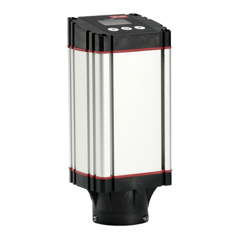
ERS AirCool plus User manual

electronic GmbH
Stettiner Str. 3
D-82110 Germering
Phone: +49-89-894132-0
Service Hotline: +49-89-894132-500
Telefax: +49-89-8418766
E-mail: info@ers-gmbh.de
WWW: http://www.ers-gmbh.de/
Manual
ERS®–AirCool®
plus
–System
SP72 – TA1C8
- 55°C + 200°C
All rights reserved. Copyright by ERS®electronic GmbH.

ERS®Manual / AirCool®
plus
-System / SP72_TA1C8 / -55°C +200°C / Ver. 02.02 I
1 Contents
1 Contents ..............................................................................I
2 Safety symbols...................................................................4
3 The AirCool®
plus
-System SP72-TA1C8...........................6
3.1 System summary..................................................................7
3.2 Description of the system ....................................................8
3.3 System specifications ..........................................................9
3.3.1 Operating conditions............................................9
3.3.2 The AirCool®
plus
-System SP72-TA1C8.............10
3.3.3 The Controller SP72............................................11
3.3.4 The Chuck TA1C8................................................11
3.4 System restrictions.............................................................12
3.5 Temperature-Time diagram................................................12
4 Transport / storage / unpacking .....................................13
4.1 Transport.............................................................................13
4.2 Storage conditions .............................................................13
4.3 Unpacking ...........................................................................14
4.3.1 Delivered components........................................14
4.4 Dimensions .........................................................................15
4.4.1 Chuck dimensions ..............................................15
4.4.2 Controller dimensions ........................................15
4.4.1 Chiller 03 dimensions.........................................16

ERS®Manual / AirCool®
plus
-System / SP72_TA1C8 / -55°C +200°C / Ver. 02.02 II
5 Setting up the system......................................................17
5.1 Interconnections Overview ................................................17
5.2 Voltage selection ................................................................18
5.3 Voltage selection Chiller 03 ...............................................20
5.4 Connections at the Chuck TA1C8......................................21
5.5 Connections at the Chiller 03.............................................22
5.6 Assembly of the tubes between Chiller 03 and
Probe Station ......................................................................23
5.6.1 Installation of tubes at Chiller 03 .......................23
5.6.2 Installation tube at Prober..................................24
6 Initial operation ................................................................25
7 Operating instructions ....................................................27
7.1 Front panel ..........................................................................27
7.2 Key functions......................................................................28
7.3 Display Elements................................................................30
8 Operating modes .............................................................31
8.1 Hold mode...........................................................................31
8.2 Standby mode.....................................................................32
8.3 Defrost mode.......................................................................32
8.4 Dew point control................................................................33

ERS®Manual / AirCool®
plus
-System / SP72_TA1C8 / -55°C +200°C / Ver. 02.02 III
9 RS232C interface .............................................................34
9.1 Interface settings................................................................34
9.2 Changing the RS 232 Settings...........................................34
9.3 Transmission protocol .......................................................35
9.4 Interface commands...........................................................36
9.5 Set commands ....................................................................36
9.6 Request commands............................................................37
10 IEEE-488 Interface (Optional)..........................................39
10.1 Setting the IEEE-Address...................................................39
10.2 IEEE 488 Communication Capabilities..............................39
10.3 Remote Control via IEEE Interface ....................................40
10.4 Set Commands....................................................................40
10.5 Set response string ............................................................41
11 Error messages................................................................43
11.1 Error handling.....................................................................46
11.1.1 Changing the power transistor ..........................46
11.1.2 Changing the power amplifier NB1....................47
11.1.3 Chuck cable check..............................................48
11.1.4 Fuse F10 at Chiller 03 .........................................50
12 Appendix...........................................................................51
12.1 Plug XR2 for serial interface ..............................................51
12.2 Conversion tables...............................................................52
12.2.1 Conversion tables international.........................52
12.2.2 Conversion tables PT100 resistance .................53
12.3 Spare parts..........................................................................54

ERS®Manual / AirCool®
plus
-System / SP72_TA1C8 / -55°C +200°C / Ver. 02.02 4
2 Safety symbols
Safety precautions (in the manual represented by safety symbols) must be observed
during all phases of operation, service and repair of this equipment. Failure to comply
with these precautions or with specific warnings elsewhere in this manual may impair
the protections provided by the equipment. In addition it violates safety standards of
design, manufacture and intended use of the instrument. ERS®electronic GmbH
assumes no liability for customers failure to comply with these requirements.
Warnings precede potentially dangerous procedures throughout this manual.
Instructions contained in the warnings must be followed.
Symbols used on the equipment and in the manual
Danger
Caution
Calls attention to a procedure, practice or condition that
could possibly cause bodily injury or death.
Calls attention to a procedure, practice or condition that
could possibly cause damage to equipment.
Calls attention to a procedure, practice or condition that
requires special attention by the reader.
The functional capability of the system can be reduced.
Advice

ERS®Manual / AirCool®
plus
-System / SP72_TA1C8 / -55°C +200°C / Ver. 02.02 5
General warnings
Indicates dangerous voltage.
Protective conductor terminal. For protection
against electrical shock in case of fault. Used with
field wiring terminals to indicate the terminal
which must be connected to ground before
operating equipment.
Danger
Caution
Work on electrical, electronical, pneumatical and
refrigerating components!
Hot chuck can cause burn. Keep hands away from HOT
Chuck at servicing!
Cold Chuck can cause frost-bite. Keep hands away from
COLD Chuck at servicing!
Work on electrical, electronical, pneumatical and
refrigerating components have to be carried out by
service-trained personnel only.
To avoid personal injury, do not perform any procedure
explained in this manual or perform any servicing unless
youarequalifiedtodoso.

ERS®Manual / AirCool®
plus
-System / SP72_TA1C8 / -55°C +200°C / Ver. 02.02 6
3 The AirCool®
plus
-System SP72-TA1C8
Fig. 3a Controller SP72
Fig. 3b Chuck TA1C8
Air connections
Vacuum
Cable to Controller SP72
˜
˜
XC1

ERS®Manual / AirCool®
plus
-System / SP72_TA1C8 / -55°C +200°C / Ver. 02.02 7
3.1 System summary
The ERS®thermo control systems are used in the semiconductor industry for
temperature characterization or failure analysis of wafers, chips or hybrids.
The AirCool®
plus
Chuck in combination with the AirCool®
plus
Controller are
particularly suitable to provide rapid temperature adjustment and a precise
environment for probing semiconductor wafers, chips or hybrids. This system has a
temperature range of -55°C to +200°C.
1 = actual temperature message
2 = electrical power control
3 = air control
4 = dew point control
5/ 6 = communication with the prober or an external computer via
interface RS232C respectively IEEE-488
AirCool®
plus
Chuck
Controller SP72
+
Chiller 03
Interface
RS232C
Power supply
Fig. 3.1a Functional block diagram of an ERS®AirCool®
plus
-Systems
Air input
1
2
3
Interface
IEEE-488
56
4
Caution
Use in other field of operation is not permitted.

ERS®Manual / AirCool®
plus
-System / SP72_TA1C8 / -55°C +200°C / Ver. 02.02 8
3.2 Description of the system
The AirCool®
plus
System provides rapid temperature adjustment and a precise
environment for probing semiconductor wafers.
The system operation temperature ranges from -55°C to + 200°C. The AirCool®
plus
System, as the name implies, uses exclusively air for cooling down to lowest
temperatures. There is no need for any water or other liquid coolants and there are
no peltier devices inside the chuck, heating is done with high reliable resistance
heater. Therefore the AirCool®
plus S
ystem is offered to the costumer as a fully
developed and field experienced product, convincing in respect to precision, high
quality and highest reliability.
The chuck model has been designed to fit perfectly into all common manual, semi-
automatic or fully automatic wafer probers.
The main components of the AirCool®
plus
Chuck System are the Controller SP72
and the Chuck TA1C8.
The AirCool®
plus
Chuck TA1C8 uses air and an accurate PT100 temperature
sensor in order to provide a precise hot or cool temperature and a precise
temperature transmission to the wafer.
The experience of more than 30 years in the area of temperature transmission and
semiconducter measurement demands are embodied in the AirCool®
plus
Chuck.It
offers especially the combination of highest mechanical precision (surface planarity),
remakable temperature uniformity and excelent electrical characteristics (low noise,
low leakage).
The top surface of the AirCool®
plus
Chuck is lapped and polished in order to
provide a maximum contact area for heat transfer to or from the wafer. Vacuum holes
and notches are located in a way that ensures an accurate fixation of the wafer and a
close contact of the chuck to the wafer.
The chuck bottom is provided with a standard interface for easy installation into the
probe station.
The Controller SP 72 continuously monitors the chuck surface temperature using a
precise platinum RTD sensor which is connected to a microprocessor controlled
close loop temperature management. It is operated via an ergonomically arranged
front panel with a very bright LED displays. It is designed for 19" standard rack
system for easy integration at the customer‘s site.
For a remote operation via PC or prober software RS232C and IEEE-488 interfaces
are available.

ERS®Manual / AirCool®
plus
-System / SP72_TA1C8 / -55°C +200°C / Ver. 02.02 9
3.3 System specifications
3.3.1 Operating conditions
Operating conditions
Ambient temperature +18°C to +28°C
Relative humidity 20% to 60%
Mains supply 100/ 115/ 200/ 230V
50/ 60Hz
450VA Controller SP72
1500VA Chiller 03
1950VA System total
Compressed air
Air supply max. 310 l/min recommended
Air pressure 6 bar (0.6Mpa, 87 PSI)
Compressed air dew point ≤-45°C
Compressed air temperature ≤+26°C
Compressed air purity 99.9% apply to 3 µm
Residual oil volume 0.01mg/ m3apply to 20°C and 7 bar
Square requirement
Controller SP72 19" rack
483mm x 144mm x 326mm
Chiller 03 422mm x 933mm x 490mm
caution
To meet the specifications the following operating
conditions must be followed.
If specifications for compressed air purity are not met,
serious damage may occur to the chuck.

ERS®Manual / AirCool®
plus
-System / SP72_TA1C8 / -55°C +200°C / Ver. 02.02 10
3.3.2 The AirCool®
plus
-System SP72-TA1C8
Temperature range -55°C to +200°C
Temperature sensor PT100, 4-line wired
Temperatur stability ±0,08°C
Thermo device Air / Heater
Temperature repeatability ±0.2°C
Transient temperature rise time after
placing the wafer at +85°C 18sec
Heating and cooling rate *)
(measured at +25°C ambient
temperature)
heating rate
cooling rate
(see also „Temperature-Time diagram“)
+25°C to +200°C 25min
-55°C to +25°C 10min
+25°C to -55°C 15min
+200°C to +25°C 10min
Power supply 100/ 115/ 200/ 230V
50/ 60Hz
Compressed air supply 310 l/min at 6.0 bar
Data specified at +25°C ambient temperature. Specifications are subject to change due technological design improvements. No
responsibility for inadvertent errors.
.
*) depends on probe station type and chuck air supply tubes installations.

ERS®Manual / AirCool®
plus
-System / SP72_TA1C8 / -55°C +200°C / Ver. 02.02 11
3.3.3 The Controller SP72
Smallest temperature preselection step ±0,1°C
Chuck temperature display resolution 0,01°C
Control method DC / PID
Interface to prober or PC RS232C or IEEE-488
Power consumption 450VA
Weight 24 kg
Dimension 19" rack 3HE
483mm x 144mm x 326mm
3.3.4 The Chuck TA1C8
Chuck surface Diameter 206mm
Chuck surface plating Nickel, optional Gold
Temperature sensor PT100, 4-line wired
Thermal transition resistance of the
chuck against the wafer <0.3°C/W
Temperature uniformity
including thermal gradient of chuck
surface
at -55°C ±1,0°C
at +25°C ±0,5°C
at >100°C ±0,5% of the actual
temperature value
Surface flatness and base parallelism -55°C ±15µm
+25°C ±8µm
+200°C ±14µm
Dielectric resistance at 100V at +25°C > 0.8*1012 Ohm
Capacitance against ground <1900pF (40 pF triaxial connected)
Height 28mm ± 0.05mm
Weight 4500g
Data specified at +25°C ambient temperature. Specifications are subject to change due to technological design improvements.
No responsibility for inadvertent errors.

ERS®Manual / AirCool®
plus
-System / SP72_TA1C8 / -55°C +200°C / Ver. 02.02 12
3.4 System restrictions
ÿAt intial operation of the whole system (chucksystem and probe station) this whole
system has to be purged with dry air for a minimum time period of 24 hours.
Therefor please close all covers of the probeshield and let the AirCool®
plus
Chuck System operate at +25°C set temperature.
This procedure is evident of removing any huminidy inside the probe station and
should be repeated after any longer period of down time.
ÿThe dew point inside the probe station will degrade in case a testhead is
provided with fans and/or the probecard area is exposed to air draft (e.g. air-
condition system).
ÿThe dew point sensor has to be recalibrated yearly.
3.5 Temperature-Time diagram
Fig. 3.5a Heating/Cooling curve

ERS®Manual / AirCool®
plus
-System / SP72_TA1C8 / -55°C +200°C / Ver. 02.02 13
4 Transport / storage / unpacking
4.1 Transport
4.2 Storage conditions
Ambient temperature 0°C to +70°C
Relative humidity 20% to 60%
Use the original package for storage!
Required space approx. 590mm x 520mm x 610mm for controller and chuck
830mm x 730mm x 1430mm for Chiller 03.
Danger
ÿMind the equipment weight!
ÿShocks should be avoided!
ÿAlways transport the the system upright!

ERS®Manual / AirCool®
plus
-System / SP72_TA1C8 / -55°C +200°C / Ver. 02.02 14
4.3 Unpacking
While unpacking please check the delivered components according to the list below:
4.3.1 Delivered components
Qty Component
1 Chuck TA1C8
1 Controller
SP72
1 Chiller 03
1
plastic bag
Dew point
sensor
1
1
1
1
1
Planarity protocol
Temperature Gradient protocol
PT100 Protocol
Manual
CD
Accessories

ERS®Manual / AirCool®
plus
-System / SP72_TA1C8 / -55°C +200°C / Ver. 02.02 15
4.4 Dimensions
4.4.1 Chuck dimensions
4.4.2 Controller dimensions
Fig. 4.4.1a Chuck TA1C8
Fig. 4.4.2a Controller SP72
∅206
37,5
A
483
132,5
144
326
376

ERS®Manual / AirCool®
plus
-System / SP72_TA1C8 / -55°C +200°C / Ver. 02.02 16
4.4.3 Chiller 03 dimensions
Fig. 4.4.3a Chiller 03
422
490 933

ERS®Manual / AirCool®
plus
-System / SP72_TA1C8 / -55°C +200°C / Ver. 02.02 17
5 Setting up the system
5.1 Interconnections Overview
Fig. 5.1a Interconnections Overview
Airpressure6bar
Dew point <-45°C
Air supply max. 310 l/min
AirCool Chuck
TA1C8
Prober
Available Chucksize: 6" or 8"
AirCool 8" Chuck System -55°C +200°C
Chiller 03
Power supply
100/110/200/230 V
50
/
60
H
z
AC1
ACM325
ACK004
AC054
XC12
XC32
P1
P7
P6
P5
P4 P3
P2
Dew point sensor ACM218
AC100
ACK005
AC02
XC1
ACK001
XR4
XR1
P2 P1 F2 F1
XR2
XR5
IEEE-488
F8 F6
XR3
In Out
Air
P12
P10
Flushing chamber
air exhaust
Pow er supply
100/110/200/230 V
50/60 Hz
Controller SP72

ERS®Manual / AirCool®
plus
-System / SP72_TA1C8 / -55°C +200°C / Ver. 02.02 18
SP72 rear panel
Voltage
selection
terminal
SP72 front panel
5.2 Voltage selection
The ERS®AirCool®
plus
system is prepared for operation at input voltage:
100V, 115V, 200V and 230V.
Voltage slelction at SP72
Disconnect from mains before opening cover!
Danger
1.
Fig. 5.2a Controller SP72 with opened cover
2. Open the cover!
3. Make connection according to mains voltage.
Fig. 5.2b Voltage selecting terminal
230V 200V 115V 100V
Select voltage
i
advice
The standard voltage setting (state at delivery) is 230V.

ERS®Manual / AirCool®
plus
-System / SP72_TA1C8 / -55°C +200°C / Ver. 02.02 19
4. Adjust F1 according to mains voltage!
F1 230V 4AT
200V 4AT
115V 8AT
100V 8AT
F2 for all voltage settings 0,315 AT
F6 for all voltage settings 6,3 AT
F8 for all voltage settings 6,3 AT
Fig. 5.2c Fuses at the rear panel of controller SP72
Fuses
F8 F6 F2 F1
XR4
XR1
P2 P1 F2 F1
XR2
XR5
IEEE-488
F8 F6
XR3
In Out
Air
This manual suits for next models
1
Table of contents
Popular Controllers manuals by other brands

OutBack Power
OutBack Power FLEXmax Extreme quick start guide

FireFlex
FireFlex FLX-PC Operation manual

Power A
Power A FUSION user manual

Plast-O-Matic
Plast-O-Matic CAFE Installation, operation & maintenance instructions

Meteo Control
Meteo Control MX-Module RS485/422 quick start guide

New lift
New lift FST Installation & commissioning