WifiTrax Model Science WFG-80 User manual

WifiTrax Model Science www.wifitrax.com WifiTrax Model Science www.wifitrax.com
(5) Use the Back hyperlink to return to the Main Menu page, then select
Dimmer Channels. Here you can adjust the brightness of each of two banks
of four lights.
(6) You can also click on each entry in the lights or dimmers list to edit the
names and DCC addresses. DCC addresses are relevant if you use the WFD-
60 WiThrottle/DCC gateway so your lights can appear as accessories on
your DCC system.
Getting more out of your WFG-80
Consult the full manual for information about the features available. For
example, you can:
•Use the Home Net option. That way you can leave your phone or
tablet connected to your home network. When you power up your
WFG-80, your phone or tablet will connect much more quickly.
•Explore the WFG-80 web pages to see the features available.
•Use the WFD-60 Gateway to control switches using IOS WiThrottle,
Android Engine Driver, TCS UWT-100 or your DCC system, while also
driving trains.
•Use Tower Operator to configure a schematic control panel to
control your switches and select routes.
•Access the WFG-80 Manual at
http://www.wifitrax.com/manuals/WFG-80/WFG-80-Manual.pdf
More Information
http://www.wifitrax.com/help/TowerOperator/help.html
Other resources:
http://www.wifitrax.com/appNotes/howToArticles.html
This product is not a toy. Keep away from children. It is not suitable for use by persons
under 14 years of age.
Warning: This product contains chemicals known to the state of California to cause
cancer, birth defects or other reproductive harm.
WifiTrax products are made in Australia using globally-sourced components and
services. Check our website for warranty information.
WifiTrax www.wifitrax.com
WFG-80 Getting Started Guide
This document is online at http://www.wifitrax.com/appNotes/quickStart/WFG-
80-Quick-Start.pdf. Please consult the full WFG-80 manual for much more detail
at http://www.wifitrax.com/manuals/WFG-80/WFG-80-Manual.pdf
Package Contents
1 x WFG-80 Module in Static Shielding Bag, this document, mounting Kit
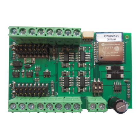
WFG-80 8-Way Lighting/General Controller
Bank 2
Bank 1
J6 Bank 2 Channel
Mode Links
J4 Bank 1 Channel
Mode Links
Power
Firmware
Upgrade
1 2 3 4 5 6 7 8
1 2 3 4 5 6 7 8
Figure 1 WFG-80 Connections

WifiTrax Model Science www.wifitrax.com WifiTrax Model Science www.wifitrax.com
Link
Linked
Open
Remarks
J4 1
OUT 1 Direct
Filament Lamp
J4 2
OUT 1 475 Ohm
LED Bright
Leave open for 1K
J4 3
OUT 2 Direct
Filament Lamp
J4 4
OUT 2 475 Ohm
LED Bright
Leave open for 1K
J4 5
OUT 3 Direct
Filament Lamp
J4 6
OUT 3 475 Ohm
LED Bright
Leave open for 1K
J4 7
OUT 4 Direct
Filament Lamp
J4 8
OUT 4 475 Ohm
LED Bright
Leave open for 1K
J6 1
OUT 8 Direct
Filament Lamp
J6 2
OUT 8 475 Ohm
LED Bright
Leave open for 1K
J6 3
OUT 7 Direct
Filament Lamp
J6 4
OUT 7 475 Ohm
LED Bright
Leave open for 1K
J6 5
OUT 6 Direct
Filament Lamp
J6 6
OUT 6 475 Ohm
LED Bright
Leave open for 1K
J6 7
OUT 5 Direct
Filament Lamp
J6 8
OUT 5 475 Ohm
LED Bright
Leave open for 1K
Table 1. Link Option Settings
Links
removed
for LEDs
D1 D2 D3 D4
D8D7D6D5
5- 5+ 6- 6+ 7+ 8+7- 8-
Bank 2 Outputs
Cathode Anode
Cathode
Anode
Switches Always in
ON position as
shown
Diodes must be connected
The correct way around
As shown.
Diodes must be connected
The correct way around
As shown.
1+ 1- 2+ 2- 3- 4-3+ 4+
2+ 2- 3+ 3- 4+ 4-
Bank 1 Outputs
DC Power
+-
Figure 2. Connection Diagram for LED Lights
Using the WFG-80 Web Pages
This is the IP Address of the WFG-80 web pages when you are connected to
its wftrx_WFG80_1_XXXXXXXX_7 network. You will not be able to access
these pages until you are connected to the module’s network.
(2) You will see the Main Menu page as below:
(3) To test the lighting channels, click or tap the Light Channels option. You will
see the screen below. The names of each channel default to the serial
number plus the channel number as shown:
(4) Assuming your lights are connected properly, tapping the button in
the State column will toggle the light on and off.

WifiTrax Model Science www.wifitrax.com WifiTrax Model Science www.wifitrax.com
(5) CHECK YOUR WIRING! Turn on the power. You may test the unit using
WFG-80 Web Pages described in the next section. Later you may decide to
use the Tower Operator App. Refer to the Tower Operator Quick Start, or
Full Help Pages for instructions on setting up a schematic control panel on
your Windows or Android computer or tablet.
Testing and Configuring your WFG-80
You can test and configure the WFG-80 using its web pages which are accessible
from any browser on IOS, Android or Windows.
Connecting using an Apple IOS Phone or Tablet
(1) Tap the Settings icon on your iPhone or iPad
(2) Tap Wi-Fi on the left-hand menu. Under Other Networks on the right, the
list should include one like wftrx_WFG80_1_XXXXXXXX_7, where XXXXXXXX
is the serial number of your unit that appears on its label. Tap that Wi-Fi
Network. You must always connect to this Network to access the WFG-80
web pages until you operate in home-net mode.
Connecting using Android
(1) Press the Home button and tap the Settings icon:
(2) Tap Connections, then Wi-Fi and select the module’s network as
above.
Connecting using Windows
On your Windows 10 desktop or laptop, click the networks icon in the system
tray and select the network described above.
Testing using the WFG-80 Web pages
(1) Once you are connected to the module’s network, open a browser such as
Safari, Chrome or Edge and type the following in the URL bar followed by
the Enter or Go key: 192.168.7.1
Links
added in
positions
shown for
bulbs
5- 5+ 6- 6+ 7+ 8+7- 8-
Bank 2 Outputs
Switches Always in
ON position as
shown
Bulbs may be connected
either way around.
1+ 1- 2+ 2- 3- 4-3+ 4+
2+ 2- 3+ 3- 4+ 4-
Bank 1 Outputs
DC Power
+-
Lamp1 Lamp2 Lamp3 Lamp4
Lamp5 Lamp6 Lamp7 Lamp8
Figure 3. Connection Diagram for Grain-of-Wheat Lamps
Links added in positions
shown for bulbs.
For LED Signals, remove
Links and connect
cathodes to negative
sides.
5- 5+ 6- 6+ 7+ 8+7- 8-
Bank 2 Outputs
Switches Always in
ON position as
shown
Always connect common wires
to positive (+) termals
1+ 1- 2+ 2- 3- 4-3+ 4+
2+ 2- 3+ 3- 4+ 4-
Bank 1 Outputs
DC Power
+-
Lamp1 Lamp2 Lamp3 Lamp4
Lamp 6
Lamp 5 Lamp 8
Lamp 7
RED
Common
Wire Red
Wire Green
Wire
RED
Common
Wire Red
Wire Green
Wire
GREEN
RED
Common
Wire
Red
Wire Green
Wire
GREEN
RED
Common
Wire
Red
Wire Green
Wire
Signal 3
Signal 4
Figure 4. Connection Diagram for 2-Light Signals

WifiTrax Model Science www.wifitrax.com WifiTrax Model Science www.wifitrax.com
Links added in positions
shown for bulbs.
For LED Signals, remove
Links and connect
cathodes to negative
sides.
5- 5+ 6- 6+ 7+ 8+7- 8-
Bank 2 Outputs
Switches Always in
ON position as
shown
Always connect common wires
to positive (+) termals
1+ 1- 2+ 2- 3- 4-3+ 4+
2+ 2- 3+ 3- 4+ 4-
Bank 1 Outputs
DC Power
+-
Lamp1 Lamp2 Lamp3
RED AMBER
Common
Wire Red
Wire Yellow
Wire
GREEN
Green
Wire
Signal 1
Lamp1
Lamp2
Lamp3
GREEN
AMBER
Common
Wire
Red
Wire Yellow
Wire
RED
Green
Wire
Signal 2
You can use channels 4 and 8
for simple lights, a 2-light signal
or combine with spare outputs
on another unit for another 3-
light signal.
Figure 5. Connection Diagram for 3-Light Signals
Installation Instructions
(1) First determine what kind of lights you wish to control. WFG-80 will
control two basic types: Light Emitting Diodes (LEDs) and low power
filament lamps such as “Grain of Wheat Bulbs”. You are advised to use
those rated around 12 Volts or less. Higher voltage bulbs can be used
but they will not be very bright. You can make the lights brighter by
using a higher power supply voltage such as 15 Volts instead of
12Volts. Also note that you can turn the dimmers to a higher setting
using Tower Operator or the WFG-80 Web pages.
You can mix LEDs and filament lamps on the same board but you must
be careful to place the links correctly. The links provide three options
for each channel, Direct, 475 Ohm series resistor and 1000 Ohm series
resistor. If you use LEDs you MUST use the 475 or 1000 Ohm option for
those channels. Direct mode will DESTROY LEDs. If you use filament
lamps you need to use Direct mode for those channels or the lamps
will be very dim. Table 1 shows the link settings.
You can also combine channels to control features with multiple lights
like signals. Tower Operator allows you to assign channels to the signal
device on the screen once it is physically connected.
(2) Wire the WFG-80 to your lights or signals according to Figure 2,
Figure 3, Figure 4 or Figure 5. If you have multiple types of device,
you can take account of more than one figure. Be sure to connect
common wires to the positive side of each of the eight channels.
(3) Note that each of the two banks can be dimmed independently
through software using the WFG-80 Web Pages or the Tower Operator
app.
(4) Note that the two DIP switches must be always in the On position.
These are only changed for firmware update.
(5) Connect power to your unit at TRKA and TRKB as shown in Figure 2
through Figure 5. It does not matter which way round you connect the
power. You can also use DCC track power but NOT AC. The power
should be between 12 and 18 volts.
Board
Components On
WFG-80
WFG-80 PCB M3 Screw
Aluminum Spacer
M3 Nut M3 Washer
Figure 6 Mounting Suggestion
(6) Mount the unit to your baseboard using the four M3 metric screws,
nuts and spacers provided. Mount the unit on a suitable piece of
board, either your baseboard (top or bottom) or a separate board
perhaps at the front of your model railroad. The component side of the
module should face away from the board as in Figure 6. If you omit
the spacers be sure not to tighten screws so that the unit bends. Take
care that no part of the unit touches any metal as this may cause a
short circuit and result in permanent damage. Do not mechanically
stress or bend the module as this may cause permanent damage. Take
care to ensure that there is adequate ventilation to avoid
overheating.
Other manuals for WFG-80
1
Other WifiTrax Model Science Controllers manuals
Popular Controllers manuals by other brands
ABB
ABB RELION 650 SERIES Commissioning manual

Emerson
Emerson Fisher 785C Instruction manual supplement
Dungs
Dungs FRSBV 10010 Series user manual
AUMA
AUMA SAVEx Series Operation instructions
Nexmosphere
Nexmosphere XPERIENCE XC-948 quick start guide

LOVATO ELECTRIC
LOVATO ELECTRIC ATL800 installation manual
