ERVOR G05 Operating instructions

Page1
NoticeG05 - 3590 503
Issue:11/2011- Rev.A
ERVOR (SCA) - 6, Rue Désiré Granet - Z.I. du Val d'Argent - 95100 ARGENTEUIL FRANCE
(33) 01 34 11 50 00 (33) 01 34 11 50 10
Web : www.ervor.com - Email : info@ervor.com
AIR COMPRESSOR
OPERATING AND
MAINTENANCE MANUAL
G05

Page2 NoticeG05 - 3590 503
Issue:11/2011- Rev.A
ERVOR (SCA) - 6, Rue Désiré Granet - Z.I. du Val d'Argent - 95100 ARGENTEUIL FRANCE
(33) 01 34 11 50 00 (33) 01 34 11 50 10
Web : www.ervor.com - Email : info@ervor.com
IMPORTANT
This operating and maintenance manual is not stipulated by contract and Ervor reserves the right
to alter its compressors, accessories and corresponding documentation without notice.
No part of this manual may be reproduced without the written permission of Ervor Compressors.
- Model............................................................. G05
- Serial number.................................................
- Ervor reference ..............................................8 101 010 Standard
......................................................................8 101 031 Bureau Véritas
......................................................................(without oil level switch)
......................................................................8 101 073 Bureau Véritas
......................................................................(with oil level switch)
......................................................................8 101 034 Lloyd’s Register
- Delivery date ..................................................
- Customer's reference sign .............................
- Orderer's reference........................................

Page3
NoticeG05 - 3590 503
Issue:11/2011- Rev.A
ERVOR (SCA) - 6, Rue Désiré Granet - Z.I. du Val d'Argent - 95100 ARGENTEUIL FRANCE
(33) 01 34 11 50 00 (33) 01 34 11 50 10
Web : www.ervor.com - Email : info@ervor.com
SUMMARY
1 - TECHNICAL DATA ....................................................................................... 5
2 - LAYOUT........................................................................................................ 6
3 - MACHINE OVERVIEW ................................................................................. 8
3 - A - WARRANTY ............................................................................................................. 8
3 - B - ORDERING FOR SPARE PARTS............................................................................ 9
4 - DESCRIPTION OF DANGER SIGNALS .................................................... 10
5 - DANGER ZONES ........................................................................................11
6 - STORAGE .................................................................................................. 13
6 - A - UNDER 3 MONTHS ............................................................................................... 13
6 - B - 1 YEAR MAXIMUM ................................................................................................ 13
6 - C - ABOVE 1 YEAR ..................................................................................................... 13
6 - D - STORAGE OIL....................................................................................................... 14
7 - INSTALLATION .......................................................................................... 15
8 - USING THE COMPRESSOR FOR THE FIRST TIME................................ 16
8 - A - SAFETY REMINDER.............................................................................................. 16
8 - B - SAFETY MEASURES ............................................................................................ 16
8 - C - FIRST START- UP ................................................................................................. 17
8 - C - 1 REMOVAL FROM STORAGE........................................................................ 17
8 - C - 2 COUPLING MOUNTING................................................................................ 17
8 - C - 3 - DIRECTION OF ROTATION......................................................................... 20
8 - C - 4 - PROCEDURE FOR STARTING ................................................................... 22
9 - SAFETY INSTRUCTIONS .......................................................................... 23
9 - A - USED OIL DISPOSAL........................................................................................ 23
10 - PREVENTATIVE MAINTENANCE............................................................ 24
10 - A - EVERY 8 HOURS................................................................................................. 24
10 - B - EVERY 50 HOURS .............................................................................................. 24
10 - C - EVERY 200 HOURS ............................................................................................ 24
10 - D - EVERY 500 HOURS ............................................................................................ 24

Page4 NoticeG05 - 3590 503
Issue:11/2011- Rev.A
ERVOR (SCA) - 6, Rue Désiré Granet - Z.I. du Val d'Argent - 95100 ARGENTEUIL FRANCE
(33) 01 34 11 50 00 (33) 01 34 11 50 10
Web : www.ervor.com - Email : info@ervor.com
SUMMARY
10 - E - EVERY 1000 HOURS .......................................................................................... 24
10 - F - EVERY 2000 HOURS............................................................................................ 25
10 - G - EVERY 3000 HOURS ........................................................................................... 25
10 - H - EVERY 4000 HOURS ........................................................................................... 25
10-I-TIGHTENINGTORQUE ........................................................................................... 25
11 - MAINTENANCE INSTRUCTIONS............................................................ 26
11 - A - COMPRESSOR LUBRICATION .......................................................................... 26
11- A - 1 - GENERAL CHARACTERISTICS OF RECOMMENDED OIL...................... 27
11 - B - CYLINDER HEADS & VALVES ............................................................................ 28
11 - B - 1 - COMPOSITION OF VALVES ON CYLINDER HEADS .............................. 28
11 - B - 2 - MAINTENANCE OF VALVES ..................................................................... 30
11 - C - PISTONS - CONNECTING RODS - CRANKSHAFTS........................ 32
11 - D - CYLINDERS,PISTONS...................................................................... 34
11 - D - 1 - CYLINDERS ............................................................................................... 34
11 - D - 2 - PISTONS .................................................................................................... 34
11 - E - PISTON RINGS.................................................................................................... 34
11 - E - 1 - MOUNTING OF RINGS .............................................................................. 35
12 - FAILURE ANALYSIS ................................................................................ 38
12 - A - START UP FAILURE ............................................................................................ 38
12 - A - 1 - THE COMPRESSOR DOES NOT START .................................................. 38
12 - B - RUNNING FAILURE ........................................................................... 38
12 - B - 1 - THE COMPRESSOR STARTS BUT TRIPS ............................................... 38
12 - B - 2 - THE COMPRESSOR RUNS BUT THERE IS NO DELIVERY PRESSURE 38
12 - B - 3 - THE COMPRESSOR HEATS ABNORMALLY ............................................ 38
13 - SPARE PARTS LIST ................................................................................ 39
13 - A - RECOMMENDED SPARE PARTS ....................................................................... 39
14 - PARTS LIST ............................................................................................. 40
15 - ANTICORROSIVE PROTECTION .......................................................... 42
15-A-INTRODUCTION .................................................................................................... 42
15- B-PROTECTION ....................................................................................................... 42

Page5
NoticeG05 - 3590 503
Issue:11/2011- Rev.A
ERVOR (SCA) - 6, Rue Désiré Granet - Z.I. du Val d'Argent - 95100 ARGENTEUIL FRANCE
(33) 01 34 11 50 00 (33) 01 34 11 50 10
Web : www.ervor.com - Email : info@ervor.com
1 - TECHNICAL DATA
- Reciprocating air compressor with lubricated stroke
- Nominal Flow at 30 bars (ANR) ..................................16,5 Nm3/H +/- 5%
- Nominal Flow at 40 bars (ANR) ..................................15,5 Nm3/H +/- 5%
- Maximum Output Pressure......................................... 40 bar
- Service Pressure........................................................16 to 40 bar
- Revolution speed ....................................................... 1450 rpm
- Maximum Noise level at 1 metre................................. 80 dB (A)
- Number of cylinders ................................................... 2 flat twin
- Number of stages....................................................... 2
- Low pressure cylinder bore......................................... 125 mm
- High pressure cylinder bore........................................ 50 mm
- Piston stroke .............................................................. 25 mm
- Cooling coil ................................................................copper coil between stages
- Absorbed power.........................................................3,68 kW
- Maximumambienttemperature.................................... +40°C(max.)
- Minimumambienttemperature .................................... - 10°C
- 2 horizontal, air-cooled cylinders
- Multi-Stage
- Revolution Speed Maximum: 1500 rpm
Minimum : 600 rpm
- Inter cooling by air
- Oil Splash Lubrifation
- Powered by electric motor or combustion engine (gasoline or diesel)
- Direct coupling with semi-elastic blades or indirect coupling by drive pulley and belts
- Weight with coupling : 52 Kg approximately

Page6 NoticeG05 - 3590 503
Issue:11/2011- Rev.A
ERVOR (SCA) - 6, Rue Désiré Granet - Z.I. du Val d'Argent - 95100 ARGENTEUIL FRANCE
(33) 01 34 11 50 00 (33) 01 34 11 50 10
Web : www.ervor.com - Email : info@ervor.com
2 - LAYOUT

Page7
NoticeG05 - 3590 503
Issue:11/2011- Rev.A
ERVOR (SCA) - 6, Rue Désiré Granet - Z.I. du Val d'Argent - 95100 ARGENTEUIL FRANCE
(33) 01 34 11 50 00 (33) 01 34 11 50 10
Web : www.ervor.com - Email : info@ervor.com
EXPLODED DIAGRAM
bronze-bushed
connecting rod
double bearing
Protective
grill
copper coil
eccentric
camshaft
differential
monobloc piston
semi-flexible
coupling light alloy
impeller
special valves

Page8 NoticeG05 - 3590 503
Issue:11/2011- Rev.A
ERVOR (SCA) - 6, Rue Désiré Granet - Z.I. du Val d'Argent - 95100 ARGENTEUIL FRANCE
(33) 01 34 11 50 00 (33) 01 34 11 50 10
Web : www.ervor.com - Email : info@ervor.com
3 - MACHINE OVERVIEW
Thank you for purchasing an ERVOR compressor.
Please read the following manual to ensure trouble free operation for many years.
3 - A - WARRANTY
)Theuseofthiscompressorisreservedonlyforpneumaticstartingof DIESELenginesorGas
engines,for allotheruses,please consultus.
)Thecompressorunithasbeenexclusivelydesignedtocompressair.
)ItisguaranteedforONEyearagainstfaultyconstructionanddefectivematerial,providedthatthe
usercomplieswiththeinstructionsgiveninthismanual.
)TheErvorguaranteeonlycoversthefreereplacementofpartsthathavebeenproveddefective
by our Technical Department.
)Theguaranteedoesnotcoverbreakdownsduetolackofmaintenanceorthenon-compliance
of instructions given for correct running of the compressor.
It is up to the user to guarantee himself against any electrical incidents by installing and
correctly connecting and mounting safety devices.
)The Ervor guarantee is limited to that of suppliers of electric engines or control devices.
)When gasoline engines are fitted, users must follow the special instructions given by the
manufacturer of the engine.
)Our guarantee is limited to the manufacturer's one.
AIR COMPRESSOR EXCLUSIVELY
NON BREATHABLE AIR
!

Page9
NoticeG05 - 3590 503
Issue:11/2011- Rev.A
ERVOR (SCA) - 6, Rue Désiré Granet - Z.I. du Val d'Argent - 95100 ARGENTEUIL FRANCE
(33) 01 34 11 50 00 (33) 01 34 11 50 10
Web : www.ervor.com - Email : info@ervor.com
3 - B - ORDERING FOR SPARE PARTS
To order spare parts please state:
- compressor type
- information written on the nameplate of the compressor
- description of the part
- reference of the part
- compressor's serial number
Page10 NoticeG05 - 3590 503
Issue:11/2011- Rev.A
ERVOR (SCA) - 6, Rue Désiré Granet - Z.I. du Val d'Argent - 95100 ARGENTEUIL FRANCE
(33) 01 34 11 50 00 (33) 01 34 11 50 10
Web : www.ervor.com - Email : info@ervor.com
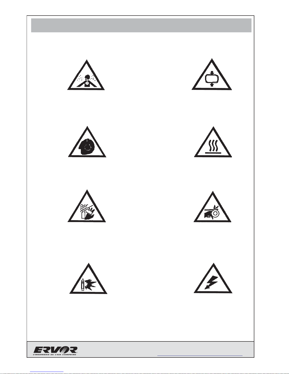
4 - DESCRIPTION OF DANGER SIGNALS
HOT PARTS
HIGH PRESSURE
MOVING PARTS
NOISE
ROTATING FAN
FLUID EJECTION DANGEROUS
ELECTRIC VOLTAGE
NON-BREATHABLE AIR

Page11
NoticeG05 - 3590 503
Issue:11/2011- Rev.A
ERVOR (SCA) - 6, Rue Désiré Granet - Z.I. du Val d'Argent - 95100 ARGENTEUIL FRANCE
(33) 01 34 11 50 00 (33) 01 34 11 50 10
Web : www.ervor.com - Email : info@ervor.com
!
5 - DANGER ZONES
ANY WORK ON THE ELECTRICAL INSTALLATION, EVEN OF MINOR
IMPORTANCE , MUST BE CARRIED OUT BY PROFESSIONALLY SKILLED
PERSONNEL.
Beware of the following risks on our compressor :

Page12 NoticeG05 - 3590 503
Issue:11/2011- Rev.A
ERVOR (SCA) - 6, Rue Désiré Granet - Z.I. du Val d'Argent - 95100 ARGENTEUIL FRANCE
(33) 01 34 11 50 00 (33) 01 34 11 50 10
Web : www.ervor.com - Email : info@ervor.com
Blankpage
Page13
NoticeG05 - 3590 503
Issue:11/2011- Rev.A
ERVOR (SCA) - 6, Rue Désiré Granet - Z.I. du Val d'Argent - 95100 ARGENTEUIL FRANCE
(33) 01 34 11 50 00 (33) 01 34 11 50 10
Web : www.ervor.com - Email : info@ervor.com
6 - STORAGE
6 - A - UNDER 3 MONTHS
)A sealed package (eg. heat-sealed plastic) to avoid dust and projections.
6 - B - 1 YEAR MAXIMUM
)Drain compressor oil carefully.
)Dismount the 1st and 2nd stage cylinder heads.
)Clean cylinder heads and valves carefully.
)Inject storage oil into the cylinder heads and valves.
)Mount the cylinder heads.
)Fill the compressor with storage oil.
)Start the compressor and run for 10 min off load; introduce 20cl of oil into
the compressor air intake.
)A sealed package (long term) category 4C with dehydrating packs, conforming to
S.E.I. norms.
6 - C - ABOVE 1 YEAR
Every year
)Drain storage oil carefully.
)Fill up with new storage oil.
)Start the compressor and run for 10min off load
)Start the compressor and run for 10min on load.
)Asealed package (long term) category 4C with dehydrating packs, conforming to
S.E.I. norms.
Page14 NoticeG05 - 3590 503
Issue:11/2011- Rev.A
ERVOR (SCA) - 6, Rue Désiré Granet - Z.I. du Val d'Argent - 95100 ARGENTEUIL FRANCE
(33) 01 34 11 50 00 (33) 01 34 11 50 10
Web : www.ervor.com - Email : info@ervor.com
6 - D - STORAGE OIL
Storage oil (Can oil 25Lref. 7 550 035) : type ANTICORIT VCI UNI-0-40
Technicaldata :
-Density at25°C :0,9-0,97 g/ml
- Flash point : min 55°C
- Viscosity at 20°C : 250 mm2/s

Page15
NoticeG05 - 3590 503
Issue:11/2011- Rev.A
ERVOR (SCA) - 6, Rue Désiré Granet - Z.I. du Val d'Argent - 95100 ARGENTEUIL FRANCE
(33) 01 34 11 50 00 (33) 01 34 11 50 10
Web : www.ervor.com - Email : info@ervor.com
7 - INSTALLATION
Technical room : The location must be clean, with good ventilation and sheltered from cold.
Thecompressormustbeplacedatminimumdistanceof400mmfromanywalloranyothermachine
for efficient cooling of the compressor. Install the compressor on a mounting plate or on a solid floor
with shock absorbers.
IF THE TECHNICAL ROOM IS TOO SMALL, FORCED VENTILATION
SHOULD BE INSTALLED FOR EFFICIENT COOLING.
THE TEMPERATURE OF THE TECHNICAL ROOM SHOULD NOT
EXCEED 40°C AT ANY TIME.
DO NOT HESITATE TO CONTACT US FOR ANY PARTICULAR
APPLICATION.
!

Page16 NoticeG05 - 3590 503
Issue:11/2011- Rev.A
ERVOR (SCA) - 6, Rue Désiré Granet - Z.I. du Val d'Argent - 95100 ARGENTEUIL FRANCE
(33) 01 34 11 50 00 (33) 01 34 11 50 10
Web : www.ervor.com - Email : info@ervor.com
8 - USING THE COMPRESSOR FOR THE FIRST TIME
8 - A - SAFETY REMINDER
)DO NOT START THE COMPRESSOR WHEN PEOPLE ARE WORKING ON IT.
)ONLY A SKILLED TECHNICIAN WHO HAS READ THIS MANUAL SHOULD
OPERATE AND/OR MAKE ADJUSTMENTS TO THE COMPRESSOR.
)NEVER START THE COMPRESSOR WITHOUT THE COUPLING PROTECTION
)NEVER CLOG THE AIR FILTER.
8 - B - SAFETY MEASURES
)BEFORE THE FIRST START-UP CHECK THE OIL LEVEL.
)CHECK THE SUPPLY VOLTAGE.

Page17
NoticeG05 - 3590 503
Issue:11/2011- Rev.A
ERVOR (SCA) - 6, Rue Désiré Granet - Z.I. du Val d'Argent - 95100 ARGENTEUIL FRANCE
(33) 01 34 11 50 00 (33) 01 34 11 50 10
Web : www.ervor.com - Email : info@ervor.com
8 - C - FIRST START- UP
8 - C - 1 REMOVAL FROM STORAGE
))
))
)Drain the storage oil from the compressor carefully.
)Fill the compressor with the recommended oil.
(see chapter "general characteristics of recommended oil").
)Start the compressor and run for 15min off load, increase pressure to maximum
service pressure for 15 minutes.
Wait for 30 minutes before draining the oil.
)Fill the compressor with the recommended oil .
)For oil level and draining see chapter "lubrication of compressors".
8 - C - 2 COUPLING MOUNTING
This coupling has been specially designed to absorb vibrations and variations between the
compressor and its drive motor. It can be used with an electric motor drive as well as a
combustion engine.
- COUPLING TYPE...................................................... AC2
- NUMBER OF BLADES .............................................. 24
- MAXIMUM POWER TRANSMITTED .........................8 CV - 5,8KW
Ervor Type AC2 couplings allow a maximum linear misalignment of up to 0°30' between the
compressor and the drive motor in all directions.
Recommendations for assembly :
))
))
)Fit the short plate boss on the end of the compressor drive shaft
))
))
)Fit the short plate boss on the end of the motor drive shaft
))
))
)Mount the drive motor onto the common frame
))
))
)Straighten block
))
))
)Fit the intermediate plate onto the plate on the drive motor side by mounting the
semi-elastic blades as shown on the following page .

Page18 NoticeG05 - 3590 503
Issue:11/2011- Rev.A
ERVOR (SCA) - 6, Rue Désiré Granet - Z.I. du Val d'Argent - 95100 ARGENTEUIL FRANCE
(33) 01 34 11 50 00 (33) 01 34 11 50 10
Web : www.ervor.com - Email : info@ervor.com
Aline the compressor by adjusting the coupling according to the measurements indicated in the
illustration below ; lightly tighten.
Assemble the semi-elastic blades between the intermediate plate and the plate on the motor
drive side.
Check setting dimensions, adjust if necessary and tighten fixings.
RULE
2mm +/-0.3
0.2mm MAXI
Horizontally & vertically
0°30' maxi 0°30' maxi
COMPRESSOR READING
WITH PLATE & SHORT HUB
INTERMEDIATE PLATE
SEMI-FLEXIBLES BLADES
ENGINE READING WITH
PLATE & LONG HUB

Page19
NoticeG05 - 3590 503
Issue:11/2011- Rev.A
ERVOR (SCA) - 6, Rue Désiré Granet - Z.I. du Val d'Argent - 95100 ARGENTEUIL FRANCE
(33) 01 34 11 50 00 (33) 01 34 11 50 10
Web : www.ervor.com - Email : info@ervor.com
!IMPORTANT :
IN THE SEMI-ELASTIC ERVOR COUPLING, DRIVINGANDABSORBTION
OF VIBRATIONS BETWEEN THE DRIVE MOTOR AND THE
COMPRESSOR ARE EFFECTED THROUGH THE SEMI-ELASTIC
BLADES.
It is absolutely necessary that after mounting, both plates should move angularly in
relation to each other.
The measurement between these two plates must be maintained while mounting.
Under no circumstances must the two plates be bonded together.
BREAKING OF SEMI-FLEXIBLE BLADES
Thisis systematicallydue toa faultin thealignment betweenthe drivemotor andcompressor
or to a fault in the distance between the plates (plates bonded together or the plates too far
apart). In case of breaking of the operating blades, check these two conditions.

Page20 NoticeG05 - 3590 503
Issue:11/2011- Rev.A
ERVOR (SCA) - 6, Rue Désiré Granet - Z.I. du Val d'Argent - 95100 ARGENTEUIL FRANCE
(33) 01 34 11 50 00 (33) 01 34 11 50 10
Web : www.ervor.com - Email : info@ervor.com
8 - C - 3 - DIRECTION OF ROTATION
Beacusethecompressorhasoilsplashlubricationyoumustmaintainthedirectionofrotationindicated
by an arrow.
Ervor compressors are normally built according to Fig. 1 (page 8).
This following shows the different direction of rotation (right or left), as well as the different positions
for mounting the oil filler pipe.
)Inform us of any non-standard mountings.
DRIVING BYAN ELECTRIC MOTOR - THREE-PHASE SUPPLY
When the power supply of the motor is connected, check the direction of rotation.
The direction of rotation of an electric motor can be inverted by reversing two of the supply wires to
the terminal box of electric motor.
DRIVING BYACOMBUSTION ENGINE - GASOLINE OR DIESEL
The combustion engines used for driving compressors are not reversible.
They always require a right-hand rotating compressor.
N.B: Exceptin thecaseof theHATZ E75 enginewhichrequires alefthand rotating compressor.
OPTIONS FOR ASSEMBLING COMPRESSORS
DEFINITION OF THE DIRECTION OF ROTATION
THE OBSERVER IS IN FRONT OF THE EXPOSED COMPRESSOR DRIVE
SHAFT
!
Table of contents
Other ERVOR Air Compressor manuals


Popular Air Compressor manuals by other brands


Clarke
Clarke HUNTER Operation & maintenance instructions

fiac
fiac New Silver Series Use & maintenance manual

KAESER KOMPRESSOREN
KAESER KOMPRESSOREN FSD SIGMA CONTROL 2 Service manual

Craftsman
Craftsman 919.167461 owner's manual

Senco
Senco PC2014 Parts reference guide

Vmac
Vmac G300003 Installation, owners and service manual