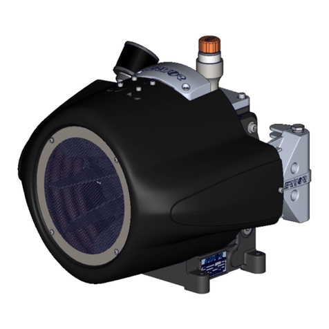
ERVOR G04 Operating instructions

Rev. : A
Date : 05/05/20
Operating and Maintenance Manual for Air compressor G04
All rights reserved copyright - We reserve the right to make technical modifications - Illustrations are not contractual
8_101_000
ERVOR (SCA) –Z.I. du Val d’Argent
6 rue Désiré Granet - 95100 ARGENTEUIL –France
(33) 1 34 11 50 00 (33) 1 34 11 50 10
Web : www.ervor.com
Page : 1/37
AIR COMPRESSOR G04
(Ref: 8101000)
OPERATING AND MAINTENANCE MANUAL

Rev. : A
Date : 05/05/20
Operating and Maintenance Manual for Air compressor G04
All rights reserved copyright - We reserve the right to make technical modifications - Illustrations are not contractual
8_101_000
ERVOR (SCA) –Z.I. du Val d’Argent
6 rue Désiré Granet - 95100 ARGENTEUIL –France
(33) 1 34 11 50 00 (33) 1 34 11 50 10
Web : www.ervor.com
Page : 2/37
- Model.............................................................................................. Reference
- G04 ........................................................................................................... ref:8101000
IMPORTANT
This operating and maintenance manual is not stipulated by contract and Ervor reserves the
right to alter its compressors, accessories and corresponding documentation without notice.
No part of this manual may be reproduced without the written permission of Ervor (SCA).
The following information must be given when ordering spares:
a. Compressor type and serial number are stamped on the compressor rating plate (see fig.1)
b. Quantity, description and parts numbers of the spares required (See chapter of this manual
or our web site www.ervor.com)
PERSONNEL SAFETY
Whenever work is to be carried out on the compressor, the electric current must be switched
off or stop engine, and the compressed air delivery must be closed.
IMPORTANT
This operating and maintenance manual is not stipulated by contract and we do
reserve ourselves the right to transform our compressors and accessories as well as
the corresponding documentation without any forewarning.
Any entire or partial reprinting of the information mentioned in this actual document
is strictly forbidden without our approval.
fig.1
G04
8
8101000

Rev. : A
Date : 05/05/20
Operating and Maintenance Manual for Air compressor G04
All rights reserved copyright - We reserve the right to make technical modifications - Illustrations are not contractual
8_101_000
ERVOR (SCA) –Z.I. du Val d’Argent
6 rue Désiré Granet - 95100 ARGENTEUIL –France
(33) 1 34 11 50 00 (33) 1 34 11 50 10
Web : www.ervor.com
Page : 3/37
Summary
1 –General presentation...........................................................................................................5
1 - 1 –Warranty.....................................................................................................................5
1 - 2 - General description......................................................................................................6
1 - 3 - Technical data G04......................................................................................................6
1 - 3 –1 –General description...............................................................................................6
2 –Installation ...........................................................................................................................8
2 - 1 –Arrangement...............................................................................................................8
2 - 2 - Coupling.......................................................................................................................8
3 –Installation example...........................................................................................................11
3 –1 - Compressor room .....................................................................................................11
3 - 2 –Lubricating oil............................................................................................................12
2 –2 –1 –Checking oil level ...............................................................................................12
3 –2 –2 –Compressor lubrication ......................................................................................13
3 –2 –3 –General characteristics of recommended oil......................................................13
4- Warning symbols.................................................................................................................14
5 –Storage..............................................................................................................................15
5 - 1 –Storage conditions ....................................................................................................15
5 - 2 –Under 3 months ........................................................................................................15
5 - 2 –1 Year maximum.......................................................................................................15
5 - 3 –Over 1 year (and each successive year)...................................................................15
6 –Sens of rotation .................................................................................................................16
6 - 1 –Splash lubrification....................................................................................................16
6 - 2 –Check sense of rotation ...........................................................................................16
6 - 3 –Definition of the sense of rotation .............................................................................16
7 –Starting ..............................................................................................................................17
7 - 1 - Safety instructions .....................................................................................................18
7 - 2 - Precautions................................................................................................................18
7 - 3 –Monitoring system.....................................................................................................18
7 - 4 –Stopping....................................................................................................................19
8 - Maintenance –Overhall - Repairs......................................................................................20
8 - 1 –LP cylinder head .......................................................................................................20
8 - 2 –HP cylinder head.......................................................................................................21
9 –Moving parts......................................................................................................................23
9 –1 –Dismounting of the crankshatf..................................................................................23
10 –Cylinders - Piston.............................................................................................................25
11 –Pistons rings....................................................................................................................26
Manufacturing reading : .......................................................................................................26
11 –1 –Mounting of rings....................................................................................................27
12 –Preventative maintenance ...............................................................................................30
12- 1 –Every 8 hours...........................................................................................................30
12- 2 –After the first 50 hours..............................................................................................30

Rev. : A
Date : 05/05/20
Operating and Maintenance Manual for Air compressor G04
All rights reserved copyright - We reserve the right to make technical modifications - Illustrations are not contractual
8_101_000
ERVOR (SCA) –Z.I. du Val d’Argent
6 rue Désiré Granet - 95100 ARGENTEUIL –France
(33) 1 34 11 50 00 (33) 1 34 11 50 10
Web : www.ervor.com
Page : 4/37
12- 3 –Every 200 hours.......................................................................................................30
12- 4 –Every 500 hours or every year.................................................................................30
12- 5 –Every 1000 hours.....................................................................................................30
12- 6 –Every 2000 hours.....................................................................................................30
12- 7 –Every 4000 hours.....................................................................................................30
13 –Tightening torque.............................................................................................................31
14 –Failures analysis..............................................................................................................32
14 –1 –Start up failure........................................................................................................32
14 –1 –A –Compressor does not start ..............................................................................32
14 –2 –Running failure.......................................................................................................32
14 –2 –A –Compressor start but trips ...............................................................................32
14 –2 –B –Compressor runs but there is no delivery pressure .........................................32
14 –2 –C –Compressor overheat......................................................................................32
15 –Spare parts list.................................................................................................................33
15 –1 –Recommended spare parts....................................................................................33
16 –Exploded view and parts list ............................................................................................34

Rev. : A
Date : 05/05/20
Operating and Maintenance Manual for Air compressor G04
All rights reserved copyright - We reserve the right to make technical modifications - Illustrations are not contractual
8_101_000
ERVOR (SCA) –Z.I. du Val d’Argent
6 rue Désiré Granet - 95100 ARGENTEUIL –France
(33) 1 34 11 50 00 (33) 1 34 11 50 10
Web : www.ervor.com
Page : 5/37
1 –General presentation
Thank you for having bought our compressor G04 recognized for its reliability and its longevity
grace by one unique design to the world since 1946.
This manual always has to stay within the reach of the user and must be attentively read to
avoid any dysfunction of the compressor
Pay special attention to the points marked
These points deal with operations which can cause damage or injury if the instructions are not
followed.
1 - 1 –Warranty Erreur ! Signet non défini.
The use of this compressor is reserved only for pneumatic starting
of DIESEL engines or Gas engines, and is not planned for a
continuous usage.
The produced air is not breathable. If the only compressor is
bought, it is necessary to install statutory safety valve.
For all other uses, please consult us.
This compressor has been specifically designed for the compression of air with an
optimal working ratio of 1/3 - 2/3 (working/stop and continuos operating time of two hours
maximum.
It is guaranteed for one year against faulty construction and defective material,
provided that the user complies with the instructions given in this manual.
The Ervor guarantee only covers the free replacement of parts that have been
proved defective by our Technical Department. Freight and labour at charge of
customer
The guarantee does not cover breakdowns due to lack of maintenance or the
non-compliance of instructions given for correct running of the compressor.
It is the user's responsibility to guarantee against any electrical incidents by
installing and correctly connecting and mounting safety devices.
For heat engines, the user has to follow the particular instructions supplied by the
manufacturer.

Rev. : A
Date : 05/05/20
Operating and Maintenance Manual for Air compressor G04
All rights reserved copyright - We reserve the right to make technical modifications - Illustrations are not contractual
8_101_000
ERVOR (SCA) –Z.I. du Val d’Argent
6 rue Désiré Granet - 95100 ARGENTEUIL –France
(33) 1 34 11 50 00 (33) 1 34 11 50 10
Web : www.ervor.com
Page : 6/37
1 - 2 - General description Erreur ! Signet non défini.
The air compressors "flat-twin " ERVOR (2 compression stages) are cooled in the air one
turbine. All the used materials are of the highest quality and corresponding in the requirements
of the organizations of classification. The lubrication is made by splash lubrication, oil sight
glass allow to verify the level of oil in the crankcase.
1 - 3 - Technical data G04
1 - 3 –1 –General description
- Capacity FAD (30 bar) 7,2 m3/H +/- 5% (50Hz)
- Capacity FAD (40 bar) 6,5 m3/H +/- 5% (50Hz)

- Working pressure 40 bar max
- Standard speed 600 to 1450 rpm-50Hz
(1745 rpm-60Hz)
- Nber of cylinders 2 Flat-twin cylinders
- Nber of compression stages 2
- Cylinder diameter LP 95 mm
- Cylinder diameter HP 40 mm
- Stroke 20 mm
- Air outlet 3/8’’ BSP Female
- Intermediate cooler Copper coil
- Power (Kw) 2,2 kW
- Maximum ambient temperature +40 °C
- Minimum ambient temperature - 10 °C
- Lubrication system Splash
- Sump capacity 1 Litre
- Weight with coupling flange 30 Kg approx.
-Optionnal equipement Oil level sensor
For any special applications, please consult us: temperature, functioning rate, service
air, etc..

Rev. : A
Date : 05/05/20
Operating and Maintenance Manual for Air compressor G04
All rights reserved copyright - We reserve the right to make technical modifications - Illustrations are not contractual
8_101_000
ERVOR (SCA) –Z.I. du Val d’Argent
6 rue Désiré Granet - 95100 ARGENTEUIL –France
(33) 1 34 11 50 00 (33) 1 34 11 50 10
Web : www.ervor.com
Page : 7/37
1 - 3 –2 –Limit conditions of use
Temperatures of use, with speed engine of 1450 rpm The indicated values are for a maximum
ambient temperature of 40°C and delivery pressure of 40 bars..
- Pressure air outlet LP stage
- Temperature air outlet LP stage
- Temperature air inlet HP stage
- Temperature air outlet HP stage
According to ambient conditions and speed, the values above
can change

Rev. : A
Date : 05/05/20
Operating and Maintenance Manual for Air compressor G04
All rights reserved copyright - We reserve the right to make technical modifications - Illustrations are not contractual
8_101_000
ERVOR (SCA) –Z.I. du Val d’Argent
6 rue Désiré Granet - 95100 ARGENTEUIL –France
(33) 1 34 11 50 00 (33) 1 34 11 50 10
Web : www.ervor.com
Page : 8/37
2 –Installation
During the installation of the compressor, make sure :
- That this one is in the horizontal and of level
- That the baseplate (provided with shock absorber, is in support on a flat ground, to
guarantee a correct functioning of the machine
2 - 1 –Arrangement
A well-dimensioned fresh air duct must be provided to the location where the compressor is to
be installed. The mouth of the duct should be as close as practically to the suction side of the
cooling fan.
2 - 2 - Coupling
This coupling has been specially designed to absorb vibrations and variations between the
compressor and its drive motor. It can be used with an electric motor drive as well as a
combustion engine.
Ervor Type AC1 couplings allow a maximum linear misalignment of up to 0°30' between the
compressor and the drive motor in all directions.

Rev. : A
Date : 05/05/20
Operating and Maintenance Manual for Air compressor G04
All rights reserved copyright - We reserve the right to make technical modifications - Illustrations are not contractual
8_101_000
ERVOR (SCA) –Z.I. du Val d’Argent
6 rue Désiré Granet - 95100 ARGENTEUIL –France
(33) 1 34 11 50 00 (33) 1 34 11 50 10
Web : www.ervor.com
Page : 9/37
0°30’ max.
Engine side with
plate and lon hub
0°30’ max.
0.2mm max.
Compressor side
(with plate and short hub)
Intermediate
plate
2mm +/-0.3
Rrecommendationsforassembly:
Fit the short hub coupling plate on the end of the compressor drive shaft.
Fit the long hub coupling plate on the end of the motor drive shaft.
Mount the drive motor onto the common frame.
Assemble the semi-elastic blades between the intermediate plate and the plate on the
motor drive side as shown below.
Align the compressor and motor by adjusting the coupling according to the measurements
indicated in the illustration below; hand tighten.
Check setting dimensions, adjust if necessary and tighten fixings.
rule
Semi-flexibles
blades
Tightening torque of the nuts
25Nm min. / 30 Nm max.

Rev. : A
Date : 05/05/20
Operating and Maintenance Manual for Air compressor G04
All rights reserved copyright - We reserve the right to make technical modifications - Illustrations are not contractual
8_101_000
ERVOR (SCA) –Z.I. du Val d’Argent
6 rue Désiré Granet - 95100 ARGENTEUIL –France
(33) 1 34 11 50 00 (33) 1 34 11 50 10
Web : www.ervor.com
Page : 10/37
IMPORTANT :
IN THE SEMI-ELASTIC ERVOR COUPLING, DRIVING AND ABSORBTION
OF VIBRATIONS BETWEEN THE DRIVE MOTOR AND THE
COMPRESSOR ARE EFFECTED THROUGH SEMI-ELASTIC BLADES.
It is absolutely necessary that after mounting, both plates should move angularly in relation to
each other.
The measurement between these two plates must be maintained while mounting.
Under no circumstances must the two plates be bonded together.
Breaking of semi-flexible blades :
This is systematically due to a fault in the alignment between the drive motor and compressor
or to a fault in the distance between the plates (plates bonded together or the plates too far
apart). In case of breaking of the operating blades, check these two conditions.

Rev. : A
Date : 05/05/20
Operating and Maintenance Manual for Air compressor G04
All rights reserved copyright - We reserve the right to make technical modifications - Illustrations are not contractual
8_101_000
ERVOR (SCA) –Z.I. du Val d’Argent
6 rue Désiré Granet - 95100 ARGENTEUIL –France
(33) 1 34 11 50 00 (33) 1 34 11 50 10
Web : www.ervor.com
Page : 11/37
3 –Installation example
3 –1 - Compressor room
The location must be clean, with good ventilation (dry, free of dust and cool).
Install the compressor on a mounting plate or on a solid floor.
Set up the compressor in such a way, that it is adequately accessible, to
ensure that operation and maintenance can be performed without any
particular difficulties.
The ambient temperature should not exceed +40°C..
Excessively high temperatures of the intake air negatively affect thequality of the compressed
air. In addition, the final compression temperature may rise excessively and which causes
abnormal operation of the compressor
If the compressor room is too small, temperature regulation should be installed. The
temperature of the compressor room do not exceed 40°C at any time.
On the other hand, the room temperature should not drop below +5°C.
Ventilation
Ensure adequate ventilation of the compressor room
Provide openings for the cooling air supply near the floor, exhaust airopenings in the ceiling or
at the top of the wall.
1 -Compressor
2 –Separator / check valve
3- Air receiver
4- Prefilter
5- Oil filter
6- Dust filter
7 –Refrigeration air dryer
ˆ 8- Adsorption air dryer
With filters
Without filter
Condensate
drainage

Rev. : A
Date : 05/05/20
Operating and Maintenance Manual for Air compressor G04
All rights reserved copyright - We reserve the right to make technical modifications - Illustrations are not contractual
8_101_000
ERVOR (SCA) –Z.I. du Val d’Argent
6 rue Désiré Granet - 95100 ARGENTEUIL –France
(33) 1 34 11 50 00 (33) 1 34 11 50 10
Web : www.ervor.com
Page : 12/37
3 - 2 –Lubricating oil
- REGULARLY CHECK OIL LEVEL : EVERY 8 HOURS OF USE
- THE VOLUME IN OIL OF THE CRANKCASE IS 1 LITRE MAX .
- FIRST DRAINING : AFTER 50 HOURS OF OPERATION
- AFTER : EVERY 500 HOURS OF OPERATION OR EVERY
12 MONTHS (vary depending on type of oil and the operating conditions)
2 –2 –1 –Checking oil level
Oil filling
Oil plug

Rev. : A
Date : 05/05/20
Operating and Maintenance Manual for Air compressor G04
All rights reserved copyright - We reserve the right to make technical modifications - Illustrations are not contractual
8_101_000
ERVOR (SCA) –Z.I. du Val d’Argent
6 rue Désiré Granet - 95100 ARGENTEUIL –France
(33) 1 34 11 50 00 (33) 1 34 11 50 10
Web : www.ervor.com
Page : 13/37
3 –2 –2 –Compressor lubrication
The G04 compressor has oil splash lubrication which gives the following advantages :
- Dispersion of oil throughout the entire compressor and avoidance of damage due to leaks or
clogging of the oil pipe.
However, it is imperative :
- to maintain the oil level in the casing above the minimum level
- that the compressor runs over its minimum speed of 600 rpm.
- to respect the indicated direction of rotation.
- to respect a max inclination of 30° on the two axis.
3–2 –3 –General characteristics of recommended oil
Ambient temperature: 0 to +30°C -15 to +45°C
Type Mineral oil Synthetic oil
Recoomended oil : ERVOR AIRLUB REGULAR P ERVOR ULTRA P
(ref : 7550014 -2L) (ref : 7550021 –2L)
Oil sumpp capacity for compressorr G04 : 1 Litre
Warning: In any event, ERVOR cannot be held responsible, even
partially, for incidents occurring as a result of the use of lubricants other
than those distributed by our company. Some lubricants are not miscible
with other lubricants so it is advisable to take maximum precautions
when changing the lubricant.

Rev. : A
Date : 05/05/20
Operating and Maintenance Manual for Air compressor G04
All rights reserved copyright - We reserve the right to make technical modifications - Illustrations are not contractual
8_101_000
ERVOR (SCA) –Z.I. du Val d’Argent
6 rue Désiré Granet - 95100 ARGENTEUIL –France
(33) 1 34 11 50 00 (33) 1 34 11 50 10
Web : www.ervor.com
Page : 14/37
4- Warning symbols
A QUALIFIED TECHNICIAN IS NECESSARY FOR ANY INTERVENTIONS
Dangerous voltage
Noise
Hot parts
Moving parts
No breathable air
High pressure
Rotaring fan
Fluid ejection

Rev. : A
Date : 05/05/20
Operating and Maintenance Manual for Air compressor G04
All rights reserved copyright - We reserve the right to make technical modifications - Illustrations are not contractual
8_101_000
ERVOR (SCA) –Z.I. du Val d’Argent
6 rue Désiré Granet - 95100 ARGENTEUIL –France
(33) 1 34 11 50 00 (33) 1 34 11 50 10
Web : www.ervor.com
Page : 15/37
5 –Storage
5 - 1 –Storage conditions
Store the equipment; preferably keep equipment in shipment crate or packaging.
Cover up the equipment with tight fitting plastic and canvas, to avoid ingression of dust and moisture.
Place the equipment on a clean and level floor.
The storage room should be well ventilated.
The floor should be free from vibration or pulsations emanating from e.g. nearby machinery.
Avoid extreme ambient temperature (temperature and moisture).
Ambient temperature during storage: +5 °C / +40 °C, with a relative humidity not exceeding 50%.
5 - 2 –Under 3 months
Close the inlet ports of the suction air intake filters with plastic plugs.
Asealed package (eg. heat-sealed plastic) to avoid dust and surface damage.
5 - 2 –1 Year maximum
Dismount the 1st and 2nd stage cylinder heads.
Using a brush:
- Lightly oil the cylinder heads and valves (with compressor lubricating oil)
Close the inlet ports of the suction air intake filters with plastic plugs.
Once a month : turn the compressor shaft a few revolutions
A sealed package (long term) category 4C conforming to S.E.I. norms, with dehydrating packs
(with color indication).
5 - 3 –Over 1 year (and each successive year)
Repeat the procedure " 1 year maximum ‘’ and replace dehydrating packs.

Rev. : A
Date : 05/05/20
Operating and Maintenance Manual for Air compressor G04
All rights reserved copyright - We reserve the right to make technical modifications - Illustrations are not contractual
8_101_000
ERVOR (SCA) –Z.I. du Val d’Argent
6 rue Désiré Granet - 95100 ARGENTEUIL –France
(33) 1 34 11 50 00 (33) 1 34 11 50 10
Web : www.ervor.com
Page : 16/37
6 –Sens of rotation
6 - 1 –Splash lubrification
The fact that the compressor has an oil splash lubrication means that you must respect the
sense of rotation, indicated by an arrow.
Our compressors are normally built accoding to Fig.1 (see next page)
The list shows the different senses of rotation right or left, as well as the different situations of
mounting of the oi ^pipe.
Inform us of any non-standard mountings.
6 - 2 –Check sense of rotation
Entraînement par moteur électrique alimentation triphasé :
Au moment du branchement de l'alimentation du moteur d'entraînement, vérifier le sens
derotation de celui-ci.Le sens de rotation d'un moteur électrique triphasé s'inverse en
intervertissant deux des filsd'alimentation à la boîte à bornes du moteur.jmkjkjkkjhkj
Driving by an electric engine –three phase feeding :
When the powr supply of the engine is connected , check the sense of rotation.
The sense of rotation of an electric engine can be inverted by reversing two of the feeding
wires to the terminal box of electric motor.
6 - 3 –Definition of the sense of rotation
The observer is in front of the exposed shaft driving of the compressor

Rev. : A
Date : 05/05/20
Operating and Maintenance Manual for Air compressor G04
All rights reserved copyright - We reserve the right to make technical modifications - Illustrations are not contractual
8_101_000
ERVOR (SCA) –Z.I. du Val d’Argent
6 rue Désiré Granet - 95100 ARGENTEUIL –France
(33) 1 34 11 50 00 (33) 1 34 11 50 10
Web : www.ervor.com
Page : 17/37
RIGHT ROTATION
LEFT HAND ROTATION
Right hand oil filling
ERVOR STANDARD
Left hand oil filling
Right hand oil filling
Left hand oil filling
Fig.1
Air outlet
Arbre
Pipe d’huile
LP
HP
LP
HP
LP
HP
LP
HP

Rev. : A
Date : 05/05/20
Operating and Maintenance Manual for Air compressor G04
All rights reserved copyright - We reserve the right to make technical modifications - Illustrations are not contractual
8_101_000
ERVOR (SCA) –Z.I. du Val d’Argent
6 rue Désiré Granet - 95100 ARGENTEUIL –France
(33) 1 34 11 50 00 (33) 1 34 11 50 10
Web : www.ervor.com
Page : 18/37
7 –Starting
7 - 1 - Safety instructions
Maintenance work, other that routine attention, shall only be undertaken when the
machine is standing still (electric network : switch off (and locked) disconnecting
switch)
Before starting the engine, ensure that all the specified protective guards are in place
Never clog air intake filter.
7 - 2 - Precautions
Before first start and after all long-term stop, control :
Direction of rotation : clockwise (looking at the drive end)
Oil level.
Instrumentation. (optional)
Voltage.
Turn over the compressor by hand.
Equipments work correctly.
Every valves are opened before starting up the compressor.
7 - 3 –Monitoring system
During operation, the user will have control at regular intervals :
- The final pressure, using pressure gauge installed on the compressed air network, or air
receiver
- Air outlet temperature with thermometer or thermostat (optional equipment)
Any abnormal deviation must be quickly identified and resolved (to see chapter "
Dysfunction"), for avoid a fast and irreversible degradation of the compressor.

Rev. : A
Date : 05/05/20
Operating and Maintenance Manual for Air compressor G04
All rights reserved copyright - We reserve the right to make technical modifications - Illustrations are not contractual
8_101_000
ERVOR (SCA) –Z.I. du Val d’Argent
6 rue Désiré Granet - 95100 ARGENTEUIL –France
(33) 1 34 11 50 00 (33) 1 34 11 50 10
Web : www.ervor.com
Page : 19/37
7 - 4 –Stopping
No action is necessary before stop the compressor.
If the compressor is to remain unused for a long time, drain oil and replace the oil by some oil
of storage. The compressor should be turned over from time to time. Opening air intake filter
and air outlet parts should be closed with plug. Put a label with the date of storage.

Rev. : A
Date : 05/05/20
Operating and Maintenance Manual for Air compressor G04
All rights reserved copyright - We reserve the right to make technical modifications - Illustrations are not contractual
8_101_000
ERVOR (SCA) –Z.I. du Val d’Argent
6 rue Désiré Granet - 95100 ARGENTEUIL –France
(33) 1 34 11 50 00 (33) 1 34 11 50 10
Web : www.ervor.com
Page : 20/37
Split pin
(ref:7436004)
Nut (ref:3933024)
10 Nm max.
Nut (ref:3933024)
10 Nm max.
Split pin
(ref:7436004)
8 - Maintenance –Overhall - Repairs
The only ones of the spare parts of origin ERVOR must be used during the
interventions at the risk of seeing the cancelled guarantee
8 - 1 –LP cylinder head
Suction
Delivery
Belleville washer (x2)
(ref:7421009)
Piston side
Manifold side
Tightening torque of the screws
25 Nm max.
Valve stem
(ref: 3925002 )
Valve
(ref:3933003)
Intake stop
(ref:3936007)
Valve spring (x2)
(ref:3933012)
Cylinder head
(ref:3923001)
Valve stem
(ref: 3925002 )
Valve
(ref:3933003)
Valve spring (x3)
(ref:3933012)
Compression stop
(ref:3936007)
Belleville washer (x2)
(ref:7421009)
This manual suits for next models
1
Table of contents
Other ERVOR Air Compressor manuals
Popular Air Compressor manuals by other brands

Chicago Pneumatic
Chicago Pneumatic QRS 20 instruction manual

Clarke
Clarke Panther 10/500 Operation & maintenance instructions

Clarke
Clarke RANGER 45 Operation & maintenance instructions

Air Liquide
Air Liquide CP 40R 6M Safety instruction for use and maintenance

Parkside
Parkside PKO 270 A4 Operating and safety instructions

Clarke
Clarke BOXER 55 Operation & maintenance instructions