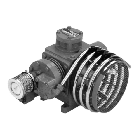
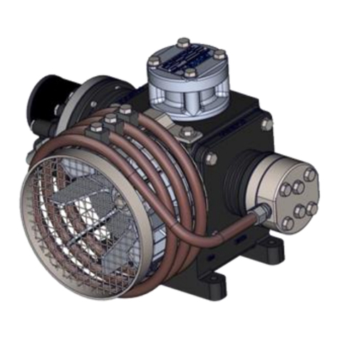
ERVOR G06 Operating instructions

Page 1
Manual G06
Edition: 10/2015 - rev A
ERVOR (SCA) - 6, Rue Désiré Granet - Z.I. du Val d'Argent - 95100 ARGENTEUIL FRANCE
(33) 01 34 11 50 00 (33) 01 34 11 50 10
Web : www.ervor.com - Email : info@ervor.com
AIR COMPRESSOR
OPERATING AND
MAINTENANCE MANUAL

Page 2
ERVOR (SCA) - 6, Rue Désiré Granet - Z.I. du Val d'Argent - 95100 ARGENTEUIL FRANCE
(33) 01 34 11 50 00 (33) 01 34 11 50 10
Web : www.ervor.com - Email : info@ervor.com
Manual G06
Edition: 10/2015 - rev A
IMPORTANT
This operating and maintenance manual is not stipulated by contract and Ervor reserves the right
to alter its compressors, accessories and corresponding documentation without notice.
No part of this manual may be reproduced without the written permission of Ervor (SCA).
- Model ......................................................................... Reference
-G06 STD ........................................................................... ref: 8 101 028
-G06 Bureau Veritas ............................................................ ref : 8 101 032
G06 Bureau Veritas (with oil level switch) ............................ ref: 8 101 075
-G06 Lloyd’s Register of Shipping (with oil level switch) ......... ref : 8 101 035
8 101 028
G06
PERSONNEL SAFETY
Whenever work is to be carried out on the compressor, the electric current must be switched
off or stop engine, and the compressed air delivery must be closed.

Page 3
Manual G06
Edition: 10/2015 - rev A
ERVOR (SCA) - 6, Rue Désiré Granet - Z.I. du Val d'Argent - 95100 ARGENTEUIL FRANCE
(33) 01 34 11 50 00 (33) 01 34 11 50 10
Web : www.ervor.com - Email : info@ervor.com
SUMMARY
1 - GENERAL PRESENTATION ........................................................................ 6
1 - A - WARRANTY ............................................................................................................. 7
2 - TECHNICAL CHARACTERISTICS .............................................................. 8
2 - A - TECHNICAL DESCRIPTION ................................................................................... 8
2 - B - MATERIAL DESCRIPTION ...................................................................................... 8
2 - C - OPERATING CHARACTERISTICS ......................................................................... 9
FAD and power graph : ............................................................................................. 10
3 - DANGER SIGNALS .....................................................................................11
Danger zones : ..........................................................................................................11
4 - LAYOUT ...................................................................................................... 12
Internal view : ........................................................................................................... 13
5 - STORAGE ................................................................................................. 14
5 - A - UNDER 3 MONTHS .............................................................................................. 14
5 - B - 1 YEAR MAXIMUM ................................................................................................ 14
5 - C - OVER 1 YEAR AND EACH SUCCESSIVE YEAR ................................................. 14
5 - D - STORAGE OIL ....................................................................................................... 14
6 - INSTALLATION ......................................................................................... 15
Installation example : ................................................................................................ 15
7 - USING THE COMPRESSOR FOR THE FIRST TIME................................ 16
7 - A - SAFETY REMINDERS .......................................................................................... 16
7 - B - SAFETY MEASURES ............................................................................................ 16
7 - C - FIRST START- UP ................................................................................................. 17
7 - C - 1 REMOVAL FROM STORAGE......................................................................... 17
7 - C - 2 COUPLING MOUNTING................................................................................ 17
7 - C - 3 DIRECTION OF ROTATION .......................................................................... 19
7 - C - 4 STARTING PROCEDURE ............................................................................. 20

Page 4
ERVOR (SCA) - 6, Rue Désiré Granet - Z.I. du Val d'Argent - 95100 ARGENTEUIL FRANCE
(33) 01 34 11 50 00 (33) 01 34 11 50 10
Web : www.ervor.com - Email : info@ervor.com
Manual G06
Edition: 10/2015 - rev A
SUMMARY
8 - SAFETY INSTRUCTIONS .......................................................................... 21
Before any adjustments : .......................................................................................... 21
9 - PREVENTATIVE MAINTENANCE .............................................................. 22
9 - A - DAILY...................................................................................................................... 22
9 - B - EVERY 25 HOURS ................................................................................................ 22
9 - C - AFTER THE FIRST 50 HOURS ............................................................................. 22
9 - D - EVERY 250 HOURS .............................................................................................. 22
9 - E - EVERY 500 HOURS OR EVERY YEAR ................................................................ 22
9 - F - EVERY 1500 HOURS ............................................................................................ 22
9 - G - EVERY 3000 HOURS ............................................................................................ 23
9 - H - EVERY YEAR ........................................................................................................ 23
10 - MAINTENANCE ....................................................................................... 24
Tightening torque :.................................................................................................... 24
10 - A - COMPRESSOR LUBRICATION .......................................................................... 24
General characteristic of recommended oil : ........................................................... 25
10 - B - CYLINDER HEADS & VALVES ................................................................................ 26
10 - B - 1 - MAINTENANCE OF VALVES ..................................................................... 27
Dismounting of valves : ........................................................................................... 27
Remounting of valves : ............................................................................................. 27
Tightening of the valve nuts : .................................................................................... 27
Frequency :............................................................................................................... 27
10 - C - MOVING PARTS .................................................................................................. 28
Dismounting of the crankshaft : ................................................................................ 28
Remounting of the crankshaft : ................................................................................. 29
Fitting of crankshaft - connecting rod - piston shaft : ............................................... 29
10 - D - CYLINDERS - PISTONS ..................................................................................... 30
10 - E - PISTON RINGS................................................................................................... 30
Check the play at cut of the piston rings : ................................................................. 30
10 - E - 1 - MOUNTING OF RINGS .............................................................................. 31
General arrangement of piston rings : ...................................................................... 31
mounting of scraper piston rings :............................................................................ 31
mounting of anti-leak piston rings : ........................................................................... 31
Ovality of cylinders : ................................................................................................. 32
Position of rings : ...................................................................................................... 32

Page 5
Manual G06
Edition: 10/2015 - rev A
ERVOR (SCA) - 6, Rue Désiré Granet - Z.I. du Val d'Argent - 95100 ARGENTEUIL FRANCE
(33) 01 34 11 50 00 (33) 01 34 11 50 10
Web : www.ervor.com - Email : info@ervor.com
SUMMARY
Mounting of cylinders :.............................................................................................. 32
Wear of the piston ring grooves :.............................................................................. 32
11 - FAILURE ANALYSIS ................................................................................ 33
11 - A - START UP FAILURE............................................................................................. 33
11 - A - 1 - THE COMPRESSOR DOES NOT START ................................................. 33
11 - B - RUNNING FAILURE ............................................................................................. 33
11 - B - 1 - THE COMPRESSOR STARTS BUT TRIPS ............................................... 33
11 - B - 2 - THE COMPRESSOR RUNS BUT THERE IS NO DELIVERY PRESSURE 33
11 - B - 3 - THE COMPRESSOR OVERHEAT ............................................................. 33
12 - SPARE PARTS LIST ................................................................................ 34
12 - A - RECOMMENDED SPARE PARTS ....................................................................... 34
13 - EXPLODED VIEW AND PARTS LIST ...................................................... 35
13 - A - GENERAL ASSEMBLY ......................................................................................... 35
13 - B - VENTILATION ASSEMBLY .................................................................................. 36
13 - C - HIGH PRESSURE ASSEMBLY ........................................................................... 38
13 - D - LOW PRESSURE ASSEMBLY ............................................................................ 40
13 - E - PISTON DRIVE ASSEMBLY ................................................................................ 42
13 - F - CASING COVER .................................................................................................. 44
13 - F - 1 WITHOUT INTEGRATED REGULATION ..................................................... 44
14 - TOOLS ...................................................................................................... 46
14 - A - GENERAL RECOMMENDATIONS ..................................................................... 46
14 - B - LIST OF TOOLS RECOMMANDED .................................................................... 47

Page 6
ERVOR (SCA) - 6, Rue Désiré Granet - Z.I. du Val d'Argent - 95100 ARGENTEUIL FRANCE
(33) 01 34 11 50 00 (33) 01 34 11 50 10
Web : www.ervor.com - Email : info@ervor.com
Manual G06
Edition: 10/2015 - rev A
1 - GENERAL PRESENTATION
We thank you first of all for buying our type G06 compressor and remind you that ERVOR compressor
s have a tradition for quality and reliability which makes them unique in their range.
This manual is considered an integral part of your new compressor. Always keep it with the compressor
where you or any other operator can easily and quickly refer to it.
Read this manual and make sure you understand it fully before operating your compressor. It can
help you avoid making mistakes in its operation.
Pay special attention to the points marked . These points deal with operations which can
cause damage or injury if the instructions are not followed.
Always follow the instructions given in this manual. They will help you get the best use and efficiency
from your new compressor.
If repair is needed, use only ORIGINAL SPARE PARTS to ensure that your compressor continues
to work efficiently for an extended working life.
!

Page 7
Manual G06
Edition: 10/2015 - rev A
ERVOR (SCA) - 6, Rue Désiré Granet - Z.I. du Val d'Argent - 95100 ARGENTEUIL FRANCE
(33) 01 34 11 50 00 (33) 01 34 11 50 10
Web : www.ervor.com - Email : info@ervor.com
AIR COMPRESSOR
EXCLUSIVELYNON BREATHABLE AIR
!
IN THE CASE OF PURCHASE OF ONLY A COMPRESSOR HEAD, THE
CUSTOMER MUST EQUIP THE COMPRESSOR WITH A CALIBRATED
SAFETY VALVE.
!
1 - A - WARRANTY
)The use of this compressor is reserved only for pneumatic starting of DIESEL engines or Gas
engines, for all other uses, please consult us.
)This compressor has been specifically designed for the compression of air with an optimal
working ratio of 1/3 - 2/3 (working/stop).
)It is guaranteed for one year against faulty construction and defective material, provided that
the user complies with the instructions given in this manual.
)The Ervor guarantee only covers the free replacement of parts that have been proved defective
by our Technical Department.
)The guarantee does not cover breakdowns due to lack of maintenance or the non-compliance
of instructions given for correct running of the compressor.
It is the user's responsibility to guarantee against any electrical incidents by installing and
correctly connecting and mounting safety devices.

Page 8
ERVOR (SCA) - 6, Rue Désiré Granet - Z.I. du Val d'Argent - 95100 ARGENTEUIL FRANCE
(33) 01 34 11 50 00 (33) 01 34 11 50 10
Web : www.ervor.com - Email : info@ervor.com
Manual G06
Edition: 10/2015 - rev A
2 - TECHNICAL CHARACTERISTICS
2 - A - TECHNICAL DESCRIPTION
- Reciprocating air compressor with lubricated stroke
- Maximum Output Pressure .......................................... 40 bar
- Service Pressure ........................................................ 0 to 40 bar
- Low pressure cylinder bore ......................................... 125 mm
- High pressure cylinder bore ........................................ 50 mm
- Piston stroke .............................................................. 38 mm
- Revolution speed: -Maximum : 1500 rpm
-Minimum : 600 rpm
- Forced air cooling by outward-flow turbine
-heat abstraction : 5.1 kW
4000 kCal/h
- Cooling ...................................................................... copper coil between stages
- Oil Splash Lubrication
- Powered by electric motor or combustion engine (petrol or diesel)
- Direct coupling with semi-elastic blades or indirect coupling by drive pulley and belts
- Ambient temperatures for operation with standard equipment from -10°c to +40°c
- Weight with AC2 coupling ........................................... 60 Kg approx
- Oil capacity ................................................................ 1.9 Litres approx
2 - B - MATERIAL DESCRIPTION
Casing :
Cast iron. Large oil capacity. Oil fill in top.
Dust-proof. Oil level sight glass.
Vent pipe from casing to the air filter.
Crankshaft :
Steel, with double bearing, and counterweight.
Connecting rod :
Aluminium, free moving on the crank shaft with bronze bush.
Piston :
Aluminium monobloc piston. Large bore, short stroke and low linear velocity.

Page 9
Manual G06
Edition: 10/2015 - rev A
ERVOR (SCA) - 6, Rue Désiré Granet - Z.I. du Val d'Argent - 95100 ARGENTEUIL FRANCE
(33) 01 34 11 50 00 (33) 01 34 11 50 10
Web : www.ervor.com - Email : info@ervor.com
Cylinders :
Cast iron. Low pressure and high pressure cylinders are directly exposed to the ventilation air
flow. Highly efficient cooling system by cooling vanes.
Cylinder head :
Steel, equipped with intake and compression valves.
Valves :
Intake and compression valves are made of annular discs which operate automatically.
Manifold :
Aluminium manifold for improved cooling with integrated pulsation damper.
Cooling :
Efficient cooling ensured by light alloy turbine and Polycarbonate cowling.
2 - C - OPERATING CHARACTERISTICS
Working at
1500 rpm
( 50Hz )
Discharge pressure
30 bar 40 bar
Nominal flow (Nm³/h)
according to ISO 1217 31 ±5% 30.5
±5%
Power consumption (KW) 6.8 7.1
Power (KW) 7.5 7.5
Average temperatures at the
air outlet for an average
ambient temperature of 25°c
- 1
st stage
- 2
nd stage
95°c
165°c
105°c
185°c

Page 10
ERVOR (SCA) - 6, Rue Désiré Granet - Z.I. du Val d'Argent - 95100 ARGENTEUIL FRANCE
(33) 01 34 11 50 00 (33) 01 34 11 50 10
Web : www.ervor.com - Email : info@ervor.com
Manual G06
Edition: 10/2015 - rev A
FAD and power graph :
Ambient temperature =25°C
Flow Power / Pressure
4,2
5,2
5,55
5,95
6,4
6,65
6,8
6,95
7,05
40
36
33,5
32,5
32,3
31,8
31,32
31,05
30,8
0
5
10
15
20
25
30
35
40
Pressure (bar)
FAD (m³/h)
power consumption (kW)
G06 Pressure
(bar)
FAD
(m³/h)
FAD
(Litres/h)
Power
consumption
0 40 665 4,2
5 36 600 5,2
10 33,5 560 5,55
15 32,5 540 5,95
20 32,3 538 6,4
25 31,8 530 6,65
30 31,32 522 6,8
35 31,05 518 6,95
40 30,8 514 7,05

Page 11
Manual G06
Edition: 10/2015 - rev A
ERVOR (SCA) - 6, Rue Désiré Granet - Z.I. du Val d'Argent - 95100 ARGENTEUIL FRANCE
(33) 01 34 11 50 00 (33) 01 34 11 50 10
Web : www.ervor.com - Email : info@ervor.com
3 - DANGER SIGNALS
Non-breathable air
noise hot parts
High pressure Rotating fan
Moving parts
Fluid ejection
Danger zones:
Dangerous electric
voltage
ANY WORK ON ELECTRICAL INSTALLATION, EVEN OF MINOR
IMPORTANCE , MUST BE CARRIED OUT BY QUALIFIED PERSONNEL.
!

Page 12
ERVOR (SCA) - 6, Rue Désiré Granet - Z.I. du Val d'Argent - 95100 ARGENTEUIL FRANCE
(33) 01 34 11 50 00 (33) 01 34 11 50 10
Web : www.ervor.com - Email : info@ervor.com
Manual G06
Edition: 10/2015 - rev A
4 - LAYOUT

Page 13
Manual G06
Edition: 10/2015 - rev A
ERVOR (SCA) - 6, Rue Désiré Granet - Z.I. du Val d'Argent - 95100 ARGENTEUIL FRANCE
(33) 01 34 11 50 00 (33) 01 34 11 50 10
Web : www.ervor.com - Email : info@ervor.com
Internal view :
Crank shaft
Double
bearing
Monobloc piston
Connecting rod
with bronze bushing
Copper coil
between stages
Fan cowling
Valves
Pulsation damper
Air filter

Page 14
ERVOR (SCA) - 6, Rue Désiré Granet - Z.I. du Val d'Argent - 95100 ARGENTEUIL FRANCE
(33) 01 34 11 50 00 (33) 01 34 11 50 10
Web : www.ervor.com - Email : info@ervor.com
Manual G06
Edition: 10/2015 - rev A
5 - STORAGE
5 - A - UNDER 3 MONTHS
)A sealed package (eg. heat-sealed plastic) to avoid dust and surface damage.
5 - B - 1 YEAR MAXIMUM
)Drain compressor oil carefully.
)Dismount the 1st and 2nd stage cylinder heads.
)Clean cylinder heads and valves carefully.
)Inject storage oil into the cylinder heads and valves.
)Mount the cylinder heads.
)Fill the compressor with storage oil.
)Start the compressor and run for 10 min off load; introduce 20cl of oil into the compressor air
intake.
)A sealed package (long term) category 4C with dehydrating packs, conforming to
S.E.I. norms.
5 - C - OVER 1 YEAR and EACH SUCCESSIVE YEAR
)Drain storage oil carefully.
)Fill up with new storage oil.
)Start the compressor and run for 10min off load
)Start the compressor and run for 10min on load.
)A sealed package (long term) category 4C with dehydrating packs, conforming to
S.E.I. norms.
5 - D - STORAGE OIL
Storage oil (Can oil 25L ref. 7 550 035) : type ANTICORIT VCI UNI-0-40
Technical data :
- Density at 25°C : 0,9-0,97 g/ml
- Flash point : min 55°C
- Viscosity at 20°C : 250 mm2/s

Page 15
Manual G06
Edition: 10/2015 - rev A
ERVOR (SCA) - 6, Rue Désiré Granet - Z.I. du Val d'Argent - 95100 ARGENTEUIL FRANCE
(33) 01 34 11 50 00 (33) 01 34 11 50 10
Web : www.ervor.com - Email : info@ervor.com
6 - INSTALLATION
Compressor room : The location must be clean, with good ventilation.
The air intake of the compressor must be placed at a minimum distance of 200 mm from any wall or
any other machine for efficient cooling of the compressor. Install the compressor on a mounting
plate or on a solid floor.
IF THE COMPRESSOR ROOM IS TOO SMALL, TEMPERATURE
REGULATION SHOULD BE INSTALLED. THE TEMPERATURE OF THE
COMPRESSOR ROOM SHOULD NOT EXCEED 40°C AT ANY TIME.
Installation example :
-1 Compressor
-2 Check valve / separator
-3 Air receiver
-4 Cooling
-5 Microfilter
-6 De-oiler filter
-7 Refrigeration drier
!

Page 16
ERVOR (SCA) - 6, Rue Désiré Granet - Z.I. du Val d'Argent - 95100 ARGENTEUIL FRANCE
(33) 01 34 11 50 00 (33) 01 34 11 50 10
Web : www.ervor.com - Email : info@ervor.com
Manual G06
Edition: 10/2015 - rev A
7 - USING THE COMPRESSOR FOR THE FIRST TIME
7 - A - SAFETY REMINDERS
))
))
)DO NOT START THE COMPRESSOR WHEN PEOPLE ARE WORKING ON IT.
))
))
)ONLY QUALIFIED PERSONNEL WHO ARE CONVERSANT WITH THE INSTRUCTIONS
IN THIS MANUAL SHOULD OPERATE AND/OR MAKE ADJUSTMENTS TO THE
COMPRESSOR AND ELECTRIC MOTOR.
))
))
)DO NOT ATTEMPT TO CARRY OUT MAINTENANCE OR REPAIRS WHILE THE MOTOR
IS RUNNING.
))
))
)NEVER START THE COMPRESSOR WITHOUT THE COUPLING PROTECTION
))
))
)NEVER CLOG THE AIR FILTER.
7 - B - SAFETY MEASURES
))
))
)BEFORE THE FIRST START-UP CHECK THE OIL LEVEL.
))
))
)CHECK THE SUPPLY VOLTAGE.
))
))
)THE SITE MUST BE CLEAN WITH GOOD VENTILATION.
))
))
)INSTALL COMPRESSOR ON LEVEL GROUND AWAY FROM HEAT SOURCE AND DUST.

Page 17
Manual G06
Edition: 10/2015 - rev A
ERVOR (SCA) - 6, Rue Désiré Granet - Z.I. du Val d'Argent - 95100 ARGENTEUIL FRANCE
(33) 01 34 11 50 00 (33) 01 34 11 50 10
Web : www.ervor.com - Email : info@ervor.com
7 - C - FIRST START- UP
7 - C - 1 REMOVAL FROM STORAGE
)Drain the storage oil from the compressor carefully.
)Fill the compressor with the recommended oil.
(see chapter "General Characteristics of recommended oil").
)Start the compressor and run for 15 minutes off load, increase pressure to maximum
service pressure for 15 minutes.
Wait for 30 minutes before draining the oil.
)Fill the compressor with the recommended oil .
)For oil level and draining see chapter "Lubrication of Compressors".
7 - C - 2 COUPLING MOUNTING
This coupling has been specially designed to absorb vibrations and variations between the
compressor and its drive motor. It can be used with an electric motor drive as well as a
combustion engine.
- COUPLING TYPE ...................................................... AC2
- NUMBER OF BLADES .............................................. 24
- MAXIMUM POWER TRANSMITTED ......................... 15 hp - 11kW
It is absolutely necessary that after mounting, both plates should move angularly in relation to
each other.
The measurement between these two plates must be maintained while mounting.
Under no circumstances must the two plates be bonded together.
BREAKING OF SEMI-FLEXIBLE BLADES
This is systematically due to a fault in the alignment between the drive motor and compressor
or to a fault in the distance between the plates (plates bonded together or the plates too far apart).
In case of breaking of the operating blades, check these two conditions.
IMPORTANT :
IN THE SEMI-ELASTIC ERVOR COUPLING, DRIVING AND ABSORBTION
OF VIBRATIONS BETWEEN THE DRIVE MOTOR AND THE
COMPRESSOR ARE EFFECTED THROUGH THE SEMI-ELASTIC
BLADES.
!

Page 18
ERVOR (SCA) - 6, Rue Désiré Granet - Z.I. du Val d'Argent - 95100 ARGENTEUIL FRANCE
(33) 01 34 11 50 00 (33) 01 34 11 50 10
Web : www.ervor.com - Email : info@ervor.com
Manual G06
Edition: 10/2015 - rev A
Ervor Type AC2 couplings allow a maximum linear misalignment of up to 0°30' between the
compressor and the drive motor in all directions.
Recommendations for assembly :
)Fit the short hub coupling plate on the end of the compressor drive shaft.
)Fit the long hub coupling plate on the end of the motor drive shaft.
)Mount the drive motor onto the common frame.
)Assemble the semi-elastic blades between the intermediate plate and the plate on the motor
drive side as shown below.
)Align the compressor and motor by adjusting the coupling according to the measurements
indicated in the illustration below; hand tighten.
)Check setting dimensions, adjust if necessary and tighten fixings.

Page 19
Manual G06
Edition: 10/2015 - rev A
ERVOR (SCA) - 6, Rue Désiré Granet - Z.I. du Val d'Argent - 95100 ARGENTEUIL FRANCE
(33) 01 34 11 50 00 (33) 01 34 11 50 10
Web : www.ervor.com - Email : info@ervor.com
7 - C - 3 - DIRECTION OF ROTATION
The G06 compressor has oil splash lubrication. To limit the oil consumption you must
respect the direction of rotation indicated by the arrow on the compressor.
It is preferable to generate the oil mist on the high pressure side. The observer in front of
the exposed compressor drive shaft will see the rotation of the coupling according to the figure
below.
THE OBSERVER IN FRONT OF THE EXPOSED COMPRESSOR DRIVE
SHAFT.
DRIVING BY AN ELECTRIC MOTOR - THREE-PHASE SUPPLY
When the power supply of the motor is connected, check the direction of rotation.
The direction of rotation of an electric motor can be reversed by inverting two of the supply
wires to the terminal box of electric motor.
DRIVING BY A COMBUSTION ENGINE - PETROL OR DIESEL
The combustion engines used for driving compressors are not reversible.
Contact us for any problem
!

Page 20
ERVOR (SCA) - 6, Rue Désiré Granet - Z.I. du Val d'Argent - 95100 ARGENTEUIL FRANCE
(33) 01 34 11 50 00 (33) 01 34 11 50 10
Web : www.ervor.com - Email : info@ervor.com
Manual G06
Edition: 10/2015 - rev A
7 - C - 4 - STARTING PROCEDURE
Air compressor :
)Check the storage oil is drained and replaced by recommended oil.
)Check oil level.
Coupling :
)Check distance between coupling plates, tightness and alignment.
)Check the coupling guard is correctly installed.
Driving :
Electric motor :
)Check the electric motor circuit breaker protection has appropriate adjustment.
)Check the direction of rotation.
)Check the power supply.
Combustion engine :
)Check oil and fuel level.
!CHECK THAT THE VOLTAGE SUPPLY IS IN ACCORDANCE
WITH THE ELECTRIC MOTOR VOLTAGE.
)Check that the engine is out of gear.
Table of contents
Other ERVOR Air Compressor manuals
Popular Air Compressor manuals by other brands

Cleveland
Cleveland CAS-10 Specifications
Bostitch
Bostitch CAP2080WB Assembly instructions

DeWalt
DeWalt DXCM271 instruction manual

Sullair
Sullair 185H Operator's manual and parts list
Champion
Champion A Series Operating and service manual
Emerson
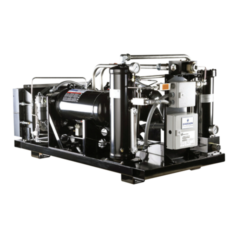
Emerson Copeland Scroll SZV32 Installation, operation & maintenance manual
