Escea EF5000 User manual
630298_3 EF5000 Installation Guide - US
Installation Manual
EF5000 - US
WARNING: If the information in this manual is not followed exactly, a fire or
explosion may result causing property damage, personal injury or loss of life.
DANGER - WHAT TO DO IF YOU SMELL GAS:
oDo not try to light any appliance.
oDo not touch any electrical switch; do not use any phone in your
building.
oImmediately call your gas supplier from a neighbour’s phone. Follow
the gas suppliers instructions.
oIf you cannot reach your gas supplier, call the fire department.
-Installation and service must be performed by a qualified installer, service
agency or gas supplier.
-Instructions must be left with the consumer and the consumer to retain
them for future reference
WARNING: Improper installation, adjustment, alteration, service or maintenance
can cause injury or property damage. Read the installation, operating and
maintenance instructions thoroughly before installing or servicing this equipment.
WARNING: For Outdoor Use Only.
DANGER
CARBON MONOXIDE HAZARD
This appliance can produce carbon monoxide which
has no odor.
Using it in an enclosed space can kill you.
Never use this appliance in an enclosed space such as
a camper, tent, car or home.
DANGER
If you smell gas:
1. Shut off gas to the appliance.
2. Extinguish any open flame.
3. If odor continues, keep away from
the appliance and immediately call
your gas supplier or fire department.
WARNING
Do not store or use gasoline or other
flammable vapors and liquids in the
vicinity of this or any other
appliance.
An LP-cylinder not connected for
use shall not be stored in the vicinity
of this or any other appliance
pour les documents français vont à www.escea.com/technical

630298_3 EF5000 Installation Guide - US
Important:
The appliance shall be installed in accordance with;
Local gas fitting and building codes, or in the absence of local codes, with the
National Fuel Gas Code, ANSI Z223.1 / NFPA 54
The appliance, when installed, must be electrically grounded in accordance with
local codes or, in the absence of local codes, with the National Electrical Code,
ANSI/NFPA 70. (If applicable)
This appliance must only be installed by an authorized person.
Warning:
The area surrounding the appliance must be clear and free from combustible materials,
gasoline and other flammable vapors and liquids.
This appliance must not be installed or used indoors.
Children and adults should be alerted to the hazards of high surface temperatures and
should stay away to avoid burns or clothing ignition.
Young children should be carefully supervised when they are in the area of the appliance.
Clothing or other flammable materials should not be hung from the appliance, or placed on
or near the appliance.
Any guard or other protective device removed for servicing the appliance must be replaced
prior to operating the appliance.
Installation and repair should be done by a qualified service person. The appliance should
be inspected before use and at least annually by a qualified service person. More frequent
cleaning may be required as necessary. It is imperative that control compartment, burners
and circulating air passageways of the appliance be kept clean.
Do not use this appliance if any part has been under water. Immediately call a qualified
service technician to inspect the appliance and to replace any part of the control system
and any gas control which has been under water.
Under no circumstances should you touch the coals or metalwork during operation.
Contact:
For further information or advice please contact the following Escea distributor:
Firebrands
630298_3 EF5000 Installation Guide - US
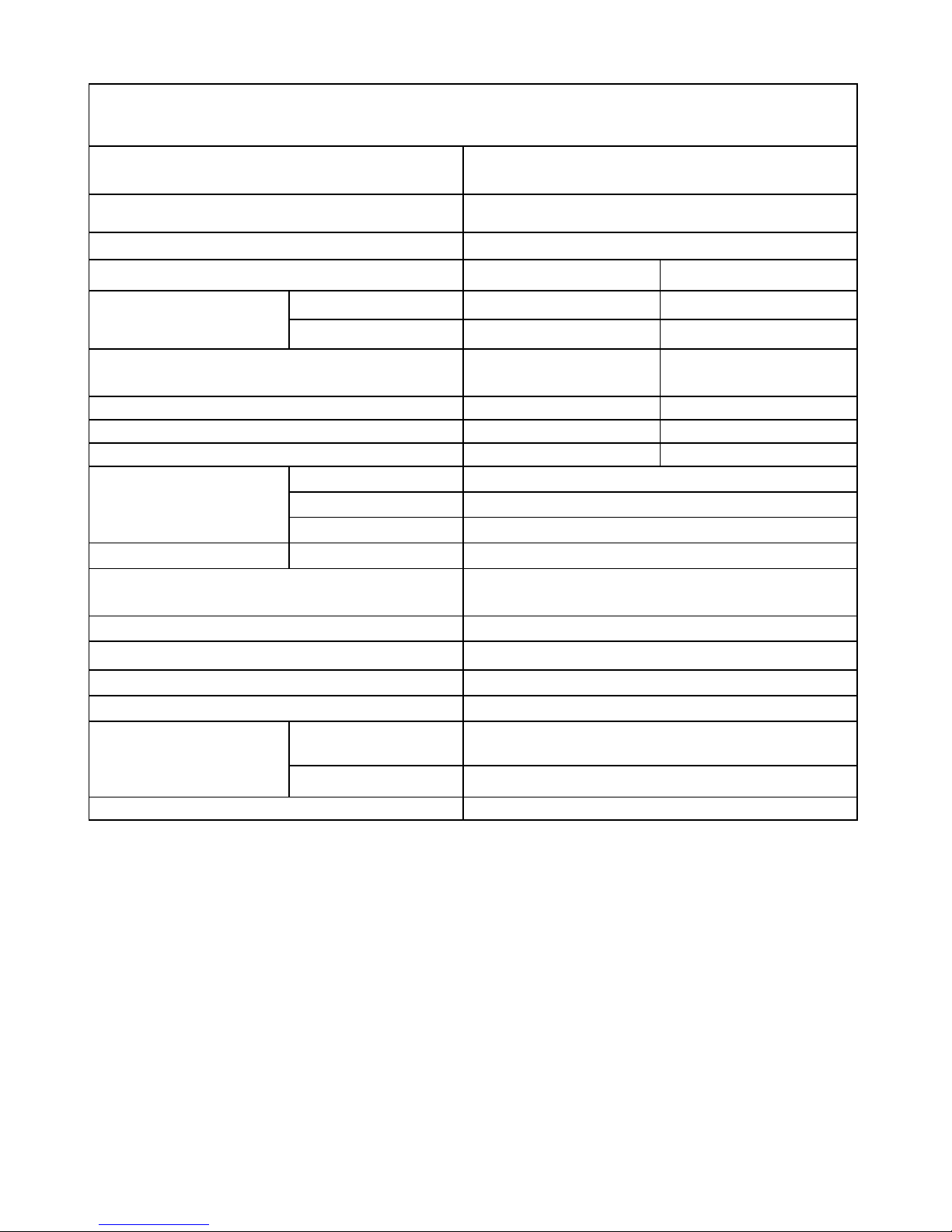
PRODUCT SPECIFICATION
MODEL NAME
EF5000
Description of Appliance
Outdoor Decorative Gas Fire
ANSI/CSA Approval No.
ANSI Z223.1 / CSA B149.1
Gas Type
Natural
Propane
Gas input
High
54000 BTU/h (57 MJ/h)
56000 BTU (59 MJ/h)
Low
36000 BTU (38 MJ/h)
40000 BTU (42MJ/h)
Operating Pressure (High)
5 inch WC (1.25 kPa)
10 inch WC (2.5 kPa)
Operating Pressure (Low)
2 inch WC (0.50 kPa)
4.5 inch WC (1.1 kPa)
Injector Size
Ø3.2mm (⅛”)
Ø 1.6mm (1/16”)
Pilot injector
Ø0.54 mm
Ø0.54 mm
Appliance Dimensions
(mm)
Width
39 ⅜” (1000 mm)
Height
22 13/16” (579 mm)
Depth
12 ⅝” (320 mm)
Weight
Kg
97 lbs/44 kg (w/o fascia)
Ignition System
Electronic Ignition to pilot system
(Maxitrol GV60)
Ignition Activation
15 secs (approx)
Flame Safeguard
Thermocouple –magnetic cartridge
Electrical Supply
6.0V DC
Consumption
2.3 W @ 0.021A 110V
Connections
Electric
Battery Pack (4 x AA Cells) or optional 6.0V DC
transformer
Gas
½ “ NPT female lower left of fireplace
Data badge location
Lower left of fireplace

630298_3 EF5000 Installation Guide - US
Contents: Page:
Product description 1.0
Power supply 2.0
Creating the cavity 3.0
Cavity Dimensions 4.0
Wall cladding around the fire 5.0
Minimum install height off the ground 6.0
Corner Installations 7.0
Laying gas pipe 8.0
Fixing the fire into the cavity 9.0
Connecting gas pipe 10.0
Connecting the power supply and touch panel 11.0
Testing of touch panel and spark ignition 12.0
Checking operating pressure 13.0
Assembly of stone cartridge 14.0
Fitting the fascia 15.0
Placement of ceramic pebbles 16.0
Operating Instructions 17.0
Maintenance and cleaning 18.0
Replacement Parts 19.0
630298_3 EF5000 Installation Guide - US
1.0 Product Description:
The Escea EF5000 flame effect gas fire is designed for outdoor use only.
This appliance requires no flue and must be permanently installed into a cavity.
It may be installed into a timber cavity.
The fire is controlled by the user, from a touch panel that is situated on the lower right hand
side of the stainless steel fascia, or if the ‘wall mount’ option is chosen, the remote will be
situated on the wall near the fire, connected by a cord.
The Data Plate, containing all technical information such as manufacture date, serial
number, gas type, jet size, etc, can be found in the lower right hand side of the fire, below
the firebox. To access this the fascia must be removed.
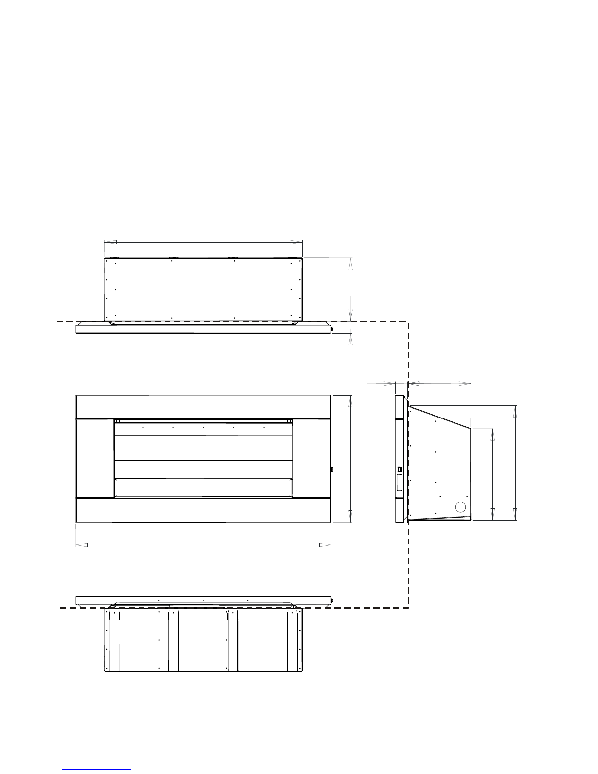
1.1 Product dimensions: (in)
25 3/8 ”
50 7/8 ”
2 3/8 ”
12 5/8 ”
18 3/16 ”
22 13/16 ”
39 3/8 ”
12 5/8 ”
2 3/8 ”
Face of the Wall
454
630298_3 EF5000 Installation Guide - US
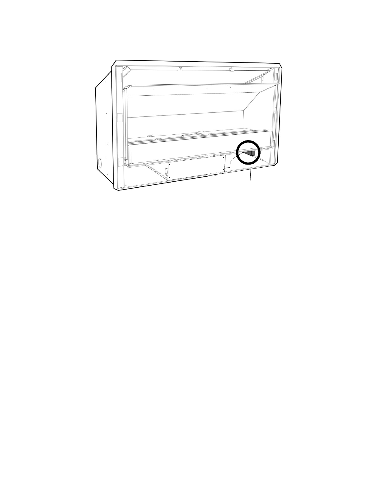
2.0 Power Supply:
This appliance requires 4 ‘AA’ sized cell batteries for operation, which are located in a
battery pack at the base of the fire against the outer wall as shown in the picture below.
Alternatively, you can use the optional external power supply; described in section 2.2 of this
manual.
2.1 Replacing Batteries:
To replace the batteries, remove the fascia to gain access to the battery pack pictured
above. Pull the battery pack away from the outer wall.
Slide the battery pack lid off to access the batteries for installation/replacement of the
batteries. Ensure you replace the batteries in the correct orientation.
Once the new batteries have been placed inside, replace the lid and reattach the battery
pack to the Velcro patch on the lower right outer wall in the fireplace.
2.2 Alternate Power Source: (Optional)
If you wish to connect your outdoor fire to mains electricity instead of using 4x AA sized
batteries, you may do so using the transformer available for purchase through your Escea
retailer capable of a 6V DC output (Make sure to provide sufficient protection to the mains
connection). Connect the transformer plug into the same location on the receiver that the
battery pack plug was connected.
Battery Pack

630298_3 EF5000 Installation Guide - US
Ideal Cavity Dimensions
ABC
39 13/16“23”13“
3.0 Creating the Cavity:
The dimensioned drawing below shows the size of opening that must be created to install
the unit.
4.0 Cavity Dimensions:
4.1 Where possible, it is recommended that the cavity is made slightly larger than the above
dimensions to give the installer the maximum amount of space to work in.
4.2 Clearances to combustibles:
Unscrew the battery panel on the
bottom of the fascia to access the batteries
A
B
B
A
C
Minimum clearance distance between a combustible
ceiling and fascia to be no less than 4’6”
Warning: Under no circumstances should any object such
as people, pets, furniture, etc. be closer than 3 feet in
front of the Escea EF5000.
Note: The 1 ½”
clearance is also
required on the
sides of the fascia
to allow access to
the control panel.
SIDE VIEW
CEILING
WALL 4'6’’ Minimum
3’
1 ” Minimum1/2
Warning: Do not install a TV above
this fire under any circumstances.

630298_3 EF5000 Installation Guide - US
5.0 Wall cladding around fire:
5.1 The temperature of the wall directly above the heater will get hot and hence may discolour
paint finishes.
5.2 Some dark coloured exhaust stains may also become visible directly above the fire due to
exhaust. In most cases this can be cleaned off with water and a brush.
6.0 Minimum install height:
The fire has ventilation gaps behind the fascia at the top and bottom. These must not be
blocked, so ensure there is a gap of at least 1 1/2”between the bottom of the fascia and
anything below.
7.0 Types of Installation:
This appliance shall only be used in an open-air situation with natural ventilation, without
stagnant areas, where gas leakage and products of combustion are rapidly dispersed by
wind and natural convection.
Certain materials or items, when placed under or near the appliance, will be subjected to
radiant heat and could become damaged.
Typically an outdoor space is not enclosed but, any enclosure in which the appliance is used
shall comply with one of the following:
- An enclosure with walls on all sides, but at least one permanent opening at
ground level and no overhead cover.
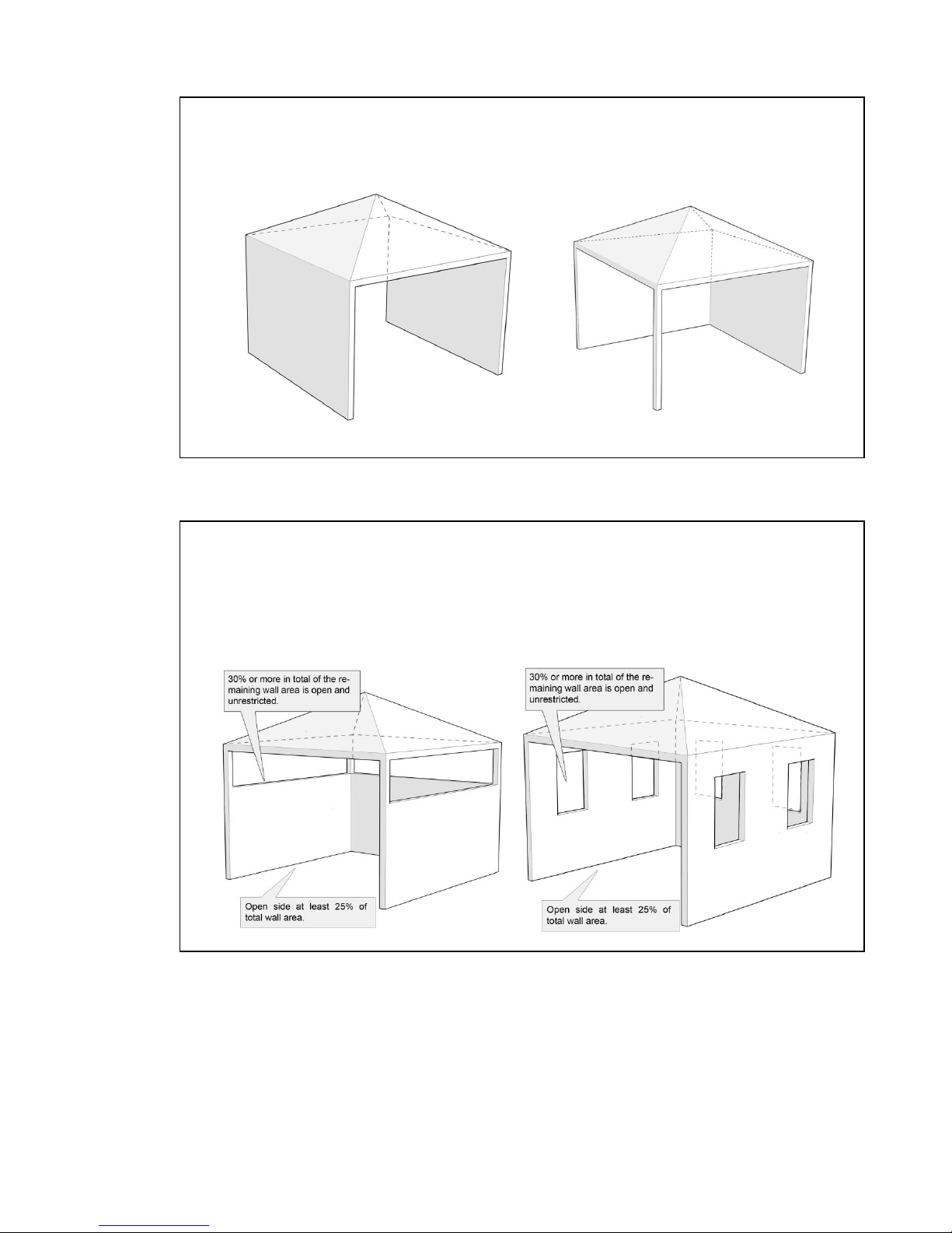
630298_3 EF5000 Installation Guide - US
- Within a partial enclosure that includes an overhead cover and no more than two
walls.
- Within a partial enclosure that includes an overhead cover and more than two
walls, the following shall apply:
At least 25% of the total wall area is completely open, and
At least 30% of the remaining wall area is open and unrestricted
Rectangular areas have been used in the above diagrams, the same principles apply to any
other shaped area.
In the case of balconies, at least 20% of the total wall area shall be and remain open and
unrestricted.
630298_3 EF5000 Installation Guide - US
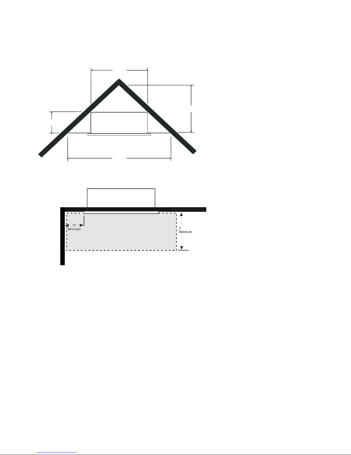
7.1Corner Installations:
If a cavity is to be created in a corner, the following drawings give the minimum sized interior
wall dimensions possible.
Note:
Allowances need to be made for
the internal cladding of the cavity.
Dimensions of the cavity in this
diagram represent the internal
size only.
39 13/16”
32 7/8”
13”
65 ¾”
Minimum clearance distance
between adjacent wall and fascia to
be no less than 11”.
630298_3 EF5000 Installation Guide - US
8.0 Laying Gas Pipe:
Gas pipe should be sized as per the requirements of your local council. The pipe sizing must
be sufficient to deliver the following volume of gas to the heater with all other gas appliances
in the home running at the same time;
EF5000 = 60 Mj/hr -56,000 Btu/hr
It is highly recommended to install an easily accessible isolating shut off valve (ball valve)
along the gas line to the EF5000 unit.
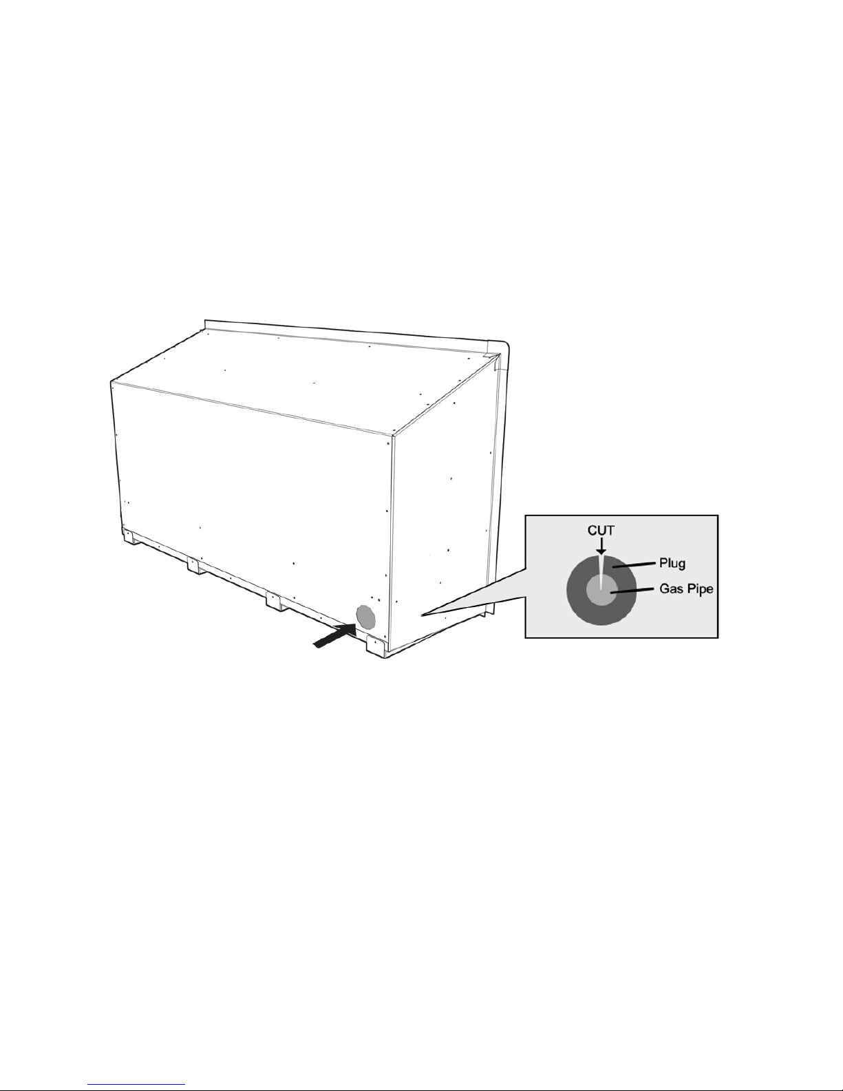
8.1 Solid pipe should be run to the inside lower left hand side of the fire. Insert the supplied
rubber plug and cut it as shown below to allow the gas pipe to pass through, keeping the
plug as air-tight as possible.
Gas Pipe Entry Point
8.2 It is required by law that an approved shut off valve (not supplied) be installed in the line
between the EF5000 Gas Fire and the gas supply.
8.3 All hoses and gas pipes must be located out of pathways where people may trip over it and
must not be in areas where the hose may be subject to accidental damage.

630298_3 EF5000 Installation Guide - US
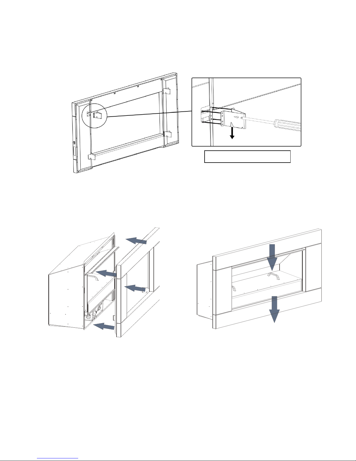
9.0 Fixing the fire into the cavity:
To fix the fire to the cavity, first drill 4 to 6 (3/16” diameter) holes in the outer flange (as
shaded grey in the picture below) in locations which will give you the most support from the
cavity framework behind, and evenly spaced around the flange. Using the supplied Stainless
Steel screws, fasten the fire to the cavity through these drilled holes.
Ensure that the fire is securely located and free from movement.
Suggested location of screws for mounting
10.0 Connecting the Gas Pipe:
When the fire unit has been pushed into position and secured the gas pipe can be
connected to the Dormont hose (1/2” NPT) at the front left of the fire. The hose and pipe
assembly should have been tested prior to this as per section 8.2.
10.1 The EF5000 must be isolated from the gas supply piping system during any pressure testing
of that system at test pressures in excess of ½ psi (14”WC).
The gas fireplace and its individual shutoff valve must be disconnected from the gas supply
piping during any pressure testing of that system at test pressures in excess of ½ psi (3.5
kPa –14” w.c.).
11.0 Connecting the Touch panel:
11.1 The Touch Panel is located on the RH side of the Fascia.
11.2 The Touch Panel socket plugs into the 5 pin plug lead situated at the front RH side of the
fire. Push them together until they ‘click’,
12.0 Testing of the Touch panel and spark ignition:
IMPORTANT: Before the operating pressure can be checked and the fascia fitted,
The touch panel and spark ignition must be tested.
12.1 This can be done with the gas supply either turned on or off.
With the power supply and touch panel connected, Lean the fascia ‘Right end’up beside the
fire and run through the steps for igniting the pilot (refer to section 17.0 for instructions).

630298_3 EF5000 Installation Guide - US
13.0 Converting the Appliance to Propane:
This appliance must be disconnected from the
gas supply piping system during any pressure
testing exceeding ½ PSI (3.5 kPa)
This is done at the valve located in the engine
of the appliance.
To access the engine, remove the screws
circled in the picture on the right.
This must be done before the fascia has been
fitted.
13.1 Changing Operating Pressure to Propane
To convert the operating pressure to
Propane you must change the maximum
and minimum pressures (refer to product
specification sheet at start of manual)
separately using the following instructions:
13.2 Setting Maximum pressure:
1. Connect a pressure manometer to the
valve outlet pressure tap. Pressure tap is
opened by turning the screw counter-
clockwise. The pressure regulator can be
reached by removing the domed-plug.
2. Turn the fireplace on and set to high flame.
3. Turn pressure regulator adjustment screw
to set required burner pressure on high
flame. Pressure is increased by turning the
screw clockwise or decreased by turning
the screw counter-clockwise.
4. After adjustment, replace the plug.
13.3Setting Minimum Pressure:
1. Turn fire on low by turning the fire down to pilot
and then pushing the flame up button until the
main burner lights.
2. Confirm low rate pressure is correct.
3. If further adjustment is needed, increase low
rate pressure by turning Allen key clockwise or
decrease low rate pressure by turning Allen key
counter-clockwise; until the pressure detailed in
the product specification sheet at the start of this manual is achieved.
4. If no other adjustments are required, close the outlet pressure tap by turning the screw
clockwise. Check all connections and pressure taps for leaks.
5. Finally, put the sticker supplied in the conversion kit onto the existing dataplate of the
EF5000.
Outlet
Pressure
Tap
Pressure Regulator
Adjustment Screw
(a domed plug
covers this)
Low Rate
Adjustment
Screw
630298_3 EF5000 Installation Guide - US
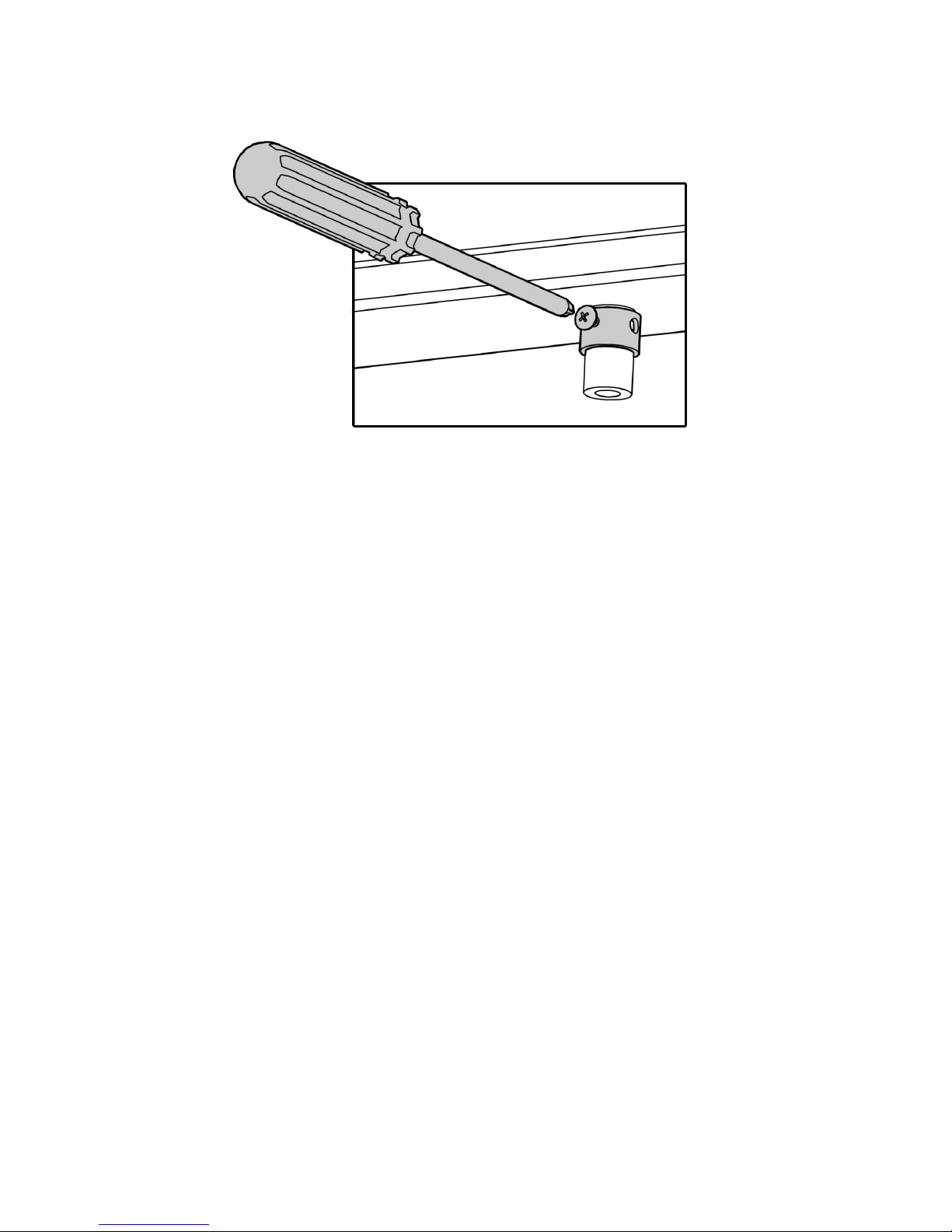
13.4 Removing Aeration Collars for Propane
For Natural Gas to Propane conversion you will also need to remove the natural gas
restrictor sleeve. The collars are located on the underside of the burners; a small screw
must be removed to get the collar off.
13.5 Swapping to Propane Main Burner Jets
Swap the main burner jets for those supplied in the conversion kit.

630298_3 EF5000 Installation Guide - US
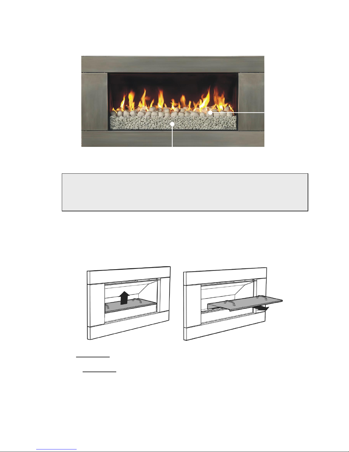
14.0 Assembly of stone cartridge:
The glass which fits inside in the stone
Cartridge has been packaged to protect it
during transit, and can be found inside the
firebox. Insert the glass strip into the stone
cartridge as shown to the right, between
the two metal flanges and push it all the
way to the bottom. A bag of pebbles
(River Stones) are also supplied, use
these to fill the stone cartridge.
14.1 With the glass in position, fix the stone cartridge to the fire by using the two supplied screws
in the location shown below. Do this before the fascia is fitted.
630298_3 EF5000 Installation Guide - US
15.0 Fitting the Fascia:
Before fitting the fascia, the hooks must be attached using the screws provided. Ensure the
two wires connecting the fascia to the fire are securely connected, as per section 11.0.
The EF5000 Stainless Steel fascia is attached to the combustion box by four ‘hooks’ on the
corners of the fascia.
15.1 Line up the hooks with the receptacles on the Outdoor Fire pictured below, and push the
fascia into position.
When you have pushed the fascia in as far as it will go, briefly push down on the fascia to
secure the fascia into position.
‘V’ in bracket to face down
630298_3 EF5000 Installation Guide - US
16.0 Placement of ceramic stones:
EF5000 fuel beds should be evenly spread out with a maximum one layer of media. Do not
heap or mound the fuel bed media, but attempt to get an even spread across the top of the
burners.
16.1 UNDER NO CIRCUMSTANCES SHOULD THE SUPPLIED
SMALL STONE PEBBLES (RIVER STONES) BE PLACED ON THE BURNERS.
THEY ARE FOR USE INSIDE THE STONE CARTRIDGE ONLY.
SOLID FUELS ARE NOT TO BE BURNED IN THIS APPLIANCE
16.2 If desired, an optional Weather Cover can be purchased from your Escea retailer, which
protects the fuelbed and burners. This should be replaced when while the fire is not in use.
16.3 To fit the weather cover ensure fire is off and cooled, and place the front edge on the glass
at the front of the fire, the rear flange of the Weather Cover will rest on the burner supports
behind the rear burner. To remove, lift the Weather Cover upwards and then towards
yourself.
16.4 The fire MUST NOT be operated while the cover is fitted.
16.5 The cover MUST NOT be fitted while the fire is hot. A cooling period of 30 minutes must be
observed before fitting.
16.6 Objects such as wood, coal, fire logs or any other solid fuels shall not be burned in the gas
fireplace.
Under no circumstances should any objects enter the gas fireplace during the start-up or
whilst the fire is running.
Ceramic
stones
River stones
630298_3 EF5000 Installation Guide - US
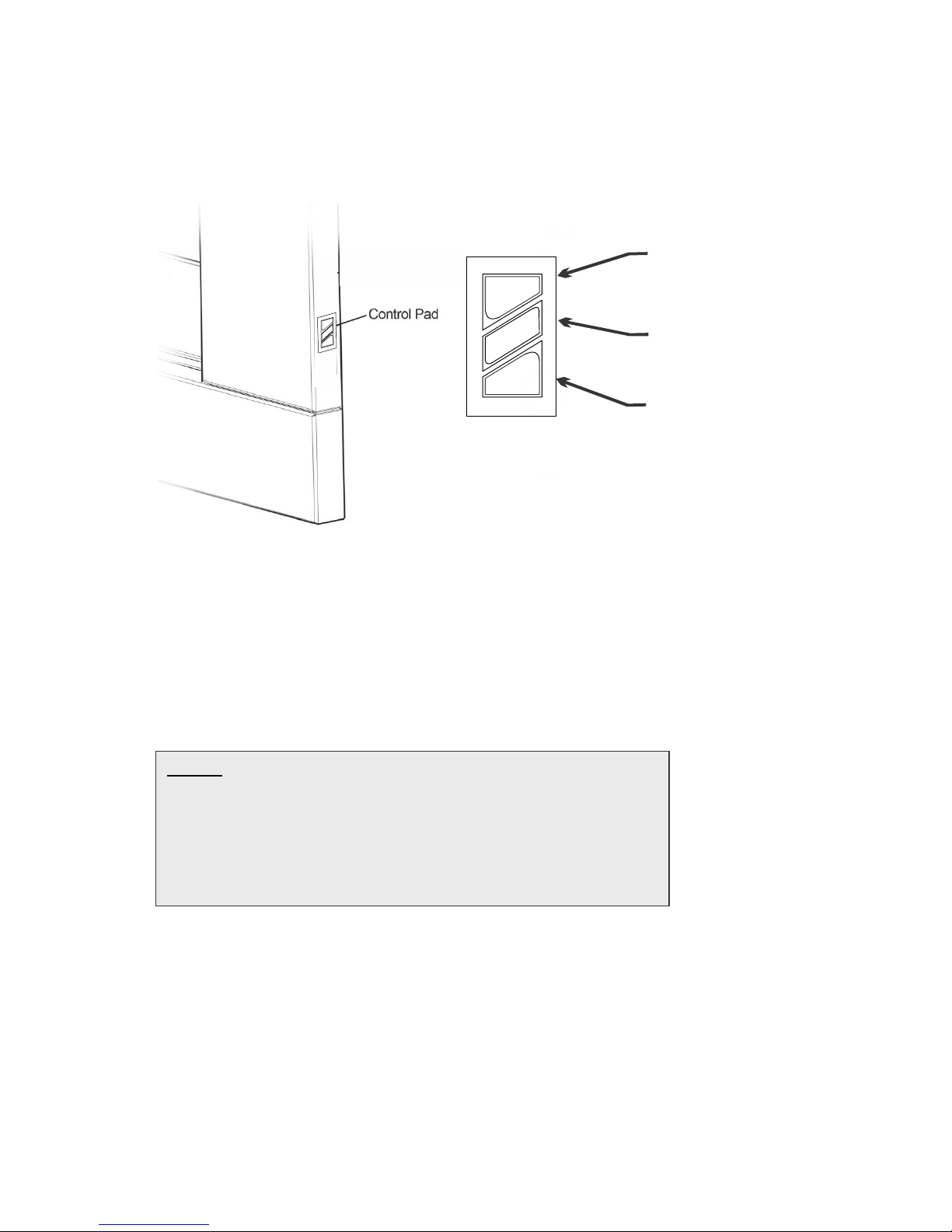
17.0 Operating Instructions:
The EF5000 is operated by the touch control panel located on the Right hand side outer
edge of the fascia. The basic operations possible from the touch control are ON/OFF and
manual adjustment of the flame height.
17.1 Igniting the pilot flame:
17.2 To turn the fireplace on push the ON-OFF button on the touch control. The pilot will start
sparking and gas will start flowing to the pilot which should light and be visible in a few
seconds.
17.3 The pilot ignition process takes a duration of 12 seconds. No other button should be pressed
during those 12 seconds. Once the pilot is lit, the main burner will automatically go to HIGH
flame after 15 seconds.
In the event of the pilot not igniting after 12 seconds press the ON/OFF button this will turn
the valve and gas off. Now repeat the process from 17.2 until the pilot ignites.
NOTE: The first time you attempt to ignite the EF5000 after
connecting it to a gas supply, will take between 1 and 4 lighting
attempts in order to let gas flow through the pipe system and
purge all air. To do this, push ‘ON-OFF’ to switch the fire on
and wait for 12 seconds. If there is a spark but no flame, push
‘ON-OFF’ again to switch off (you will hear 2 short beeps) and
then repeat until you get a pilot flame.
On/Off
FlameUp
FlameDown
UP
DOWN
ON-OFF

630298_3 EF5000 Installation Guide - US
17.4 Pilot Flame and Burner Positioning
17.5 Adjusting the flame height
While the fire is on, push the FLAME UP button or the FLAME
DOWN button to increase or decrease the flame height.
17.6 If the FLAME UP button is pushed while the fire is in HIGH
burner flame position, nothing will happen. Similarly if the
FLAME DOWN button is pushed while fire is in the PILOT
flame position, nothing will happen.
17.7 Turning off the fire
To turn the fire off, you must push the ON/OFF button this will shut down the gas flow to the
pilot flame and both burners.
630298_3 EF5000 Installation Guide - US
18.0 Maintenance and Cleaning
The unit must be cold before starting any form of maintenance or cleaning. To remove the
glass and stones in the front stone tray simply reverse the steps in section 15.0. The glass
can be cleaned using standard window cleaner and the quartz stones can be washed using
soapy water
18.1 For Stainless Steel Fascias:
1. Ensure that the Gas Fireplace is off, and that the fascia is cold.
2. Using the gloves provided with your fascia, remove the towelette from the sachet and
wipe the fascia with even, straight strokes.
3. Make sure your strokes follow the direction of the grain or brush finish. Wiping across the
grain can leave small scratches.
4. The wipe will leave a very fine film over the fascia, ensure this film is distributed evenly.
5. If the film is applied too heavily and is quite visible, you can remove the excess by gently
wiping dry with a microfibre cloth. Ensure your strokes still follow the direction of the grain or
brush finish.
6. Ensure that no film is applied to the glass of your Escea Gas Fireplace. If applied
accidentally, wipe off with an absorbent microfibre cloth.
For Powder Coated Fascias:
1. Ensure that the Gas Fireplace is off, and that the fascia is cold to the touch.
2. Using the gloves provided with your fascia, gently clean the fascia with a non-abrasive
cloth and warm soapy water.
3. Wipe off with an absorbent microfibre cloth.
Cleaning of the burners and ceramic stones can be carried out using a brush and a dry cloth
and should be done at least annually. This will remove carbon or soot build-up. If there is
evidence that the burner is damaged in any way it must be replaced prior to the appliance
being operated, and must only be replaced with an official Escea replacement part.
Periodically the pilot and burners should be checked visually for carbon and soot build-up,
consistent flame and clean burning.
18.2 Periodical visual checks of the pilot and burner flames should be carried out to ensure
consistent flame and clean burning, then turn off the battery isolating switch.
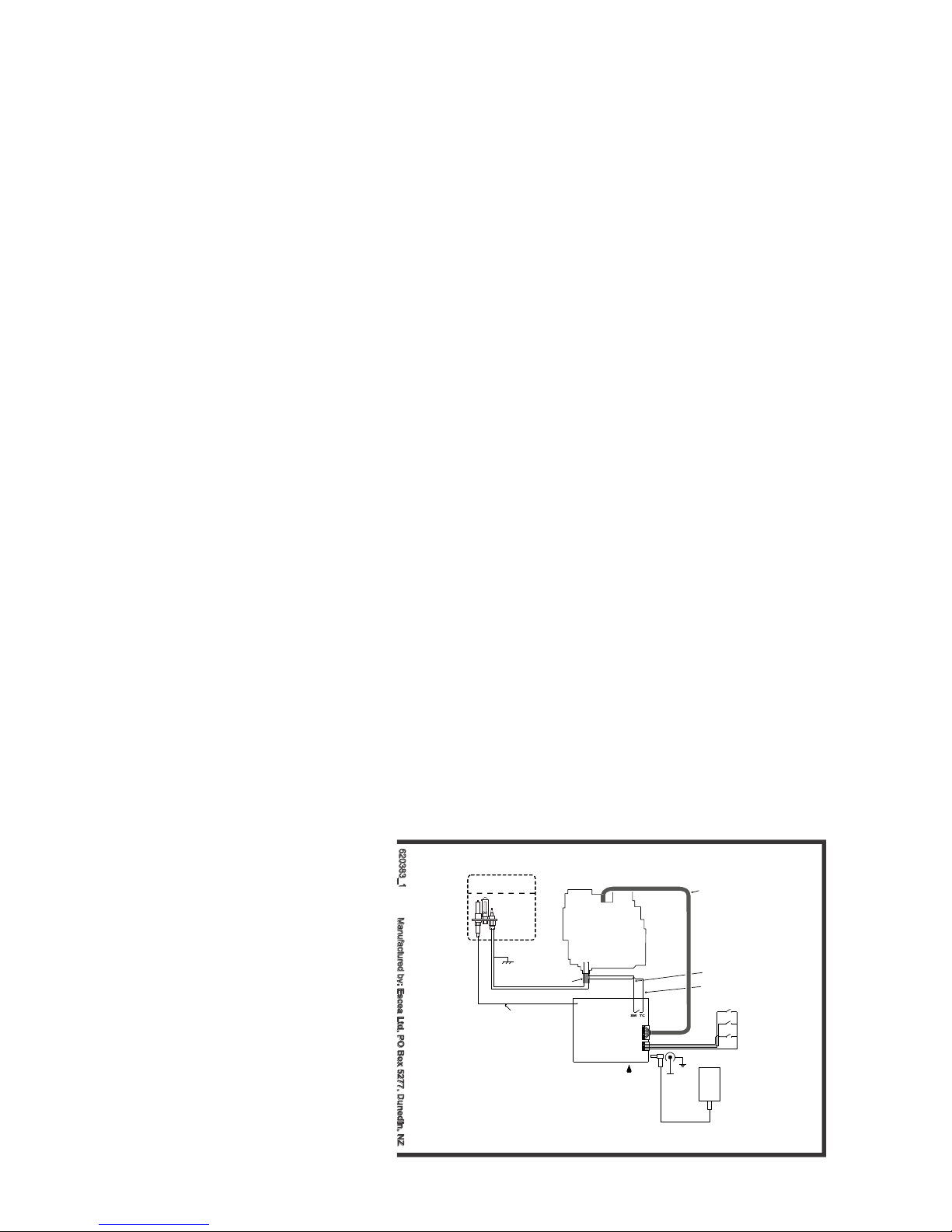
19.0 Electrical Schematic
R
C US
Pilot Burner
Membrane Switch
Receiver
T Shermocurrent Cable W
T Thermocurrent Cable C
8 Wire Cable
Interrupter Block
Power Supply
Ignition Cable
Reset Button
GV60 Valve
Main Burner
UP
ON/OFF
DOWN
+6VDC
Other manuals for EF5000
12
Table of contents
Other Escea Outdoor Fireplace manuals


Popular Outdoor Fireplace manuals by other brands


BOND MANUFACTURING
BOND MANUFACTURING Signature Series owner's manual

La Hacienda
La Hacienda Pyrrhus Firepit User instructions

pleasant hearth
pleasant hearth TRAVERSE manual

Uixe
Uixe F200061-A1 manual

Uniflame
Uniflame GAD1399SP owner's manual

Mayer Barbecue
Mayer Barbecue HEIZA MGK-220 Assembly instructions


